


WHOLE HOUSE HUMIDIFIER
Model: TM-2000
Housing Assembly
Plastic Tubing (3-10’ Sections)
10’ Power Supply Wire
Remote |
|
Nozzle Bracket |
120VAC/24VAC |
Saddle Valve Assembly |
Transformer |
The TM-2000 Humidifier is activated by heated air being produced by your furnace. Its thermal sensing circuitry monitors the temperature of the heated air. When the air is warm enough, the Housing Assembly’s electric water valve is actuated, opening to allow cold water from your plumbing system to be atomized into a fine mist. This mist is discharged into the heated air by the Remote Nozzle Bracket Assembly, where it immediately evaporates and is distributed throughout your household. The TM-2000 is supplied water from your plumbing system by the Saddle Valve Assembly, and is safely powered with reduced voltage by the 120/24 VAC Transformer, which plugs into an ordinary 120-volt wall outlet.
The TM-2000 is ideal for use with conventional gas or oil forced-air central heating systems.
WARNING: The TM-2000 is not be used on 90+ condensing furnaces, electric heat pumps or homes with well-water systems.
ITEMS INCLUDED IN KIT: (DO NOT INSTALL HUMIDIFIER IF ALL OF THESE ITEMS ARE NOT PRESENT!)
Housing Assembly |
Remote Nozzle Bracket |
||
Plastic Tubing (3 - 10' Sections) |
Saddle Valve Assembly |
||
Housing Mounting Template |
Includes 5 Each: Compression Nuts, sleeves, and inserts |
||
Remote Mounting Template |
Mounting Components |
||
Power Supply Wire |
Includes: (4) |
#8-15 |
X 3/4" Hex Head Housing |
Quick Connect Terminals (2) |
(3) |
#8-15 |
X 1/2" Hex Head Remote |
120/24 VAC Transformer |
|
Bracket Mounting Screws |
|
Instruction Manual |
(3) #8 Speed Nuts For Remote Bracket Mounting. |
||
OPTIONAL ACCESSORIES:
Air Booster Activator Kit Humidistat
NOTE: The TM-2000 is designed to operate on normal city water supply pressure. If any other type of water supply is to be used it must be capable of providing a minimum pressure of 50 psi.
DO NOT DESTROY
English ...... |
Page 1 |
Français..... |
Page 8 |
Espanõl ..... |
Page 14 |
READ AND SAVE THESE INSTRUCTIONS FOR FUTURE REFERENCE OF REPLACEMENT PARTS, OPTIONAL
COMPONENTS, AND TROUBLESHOOTING INFORMATION.
PRODUCT QUESTIONS…
CALL FIELD FIRST
for answers on product maintenance, operation or replacement part questions.
Phone: (252)522-3031
E-mail: fieldtec@fieldcontrols.com

INSTALLATION AND ADJUSTMENT
PLEASE READ COMPLETELY BEFORE BEGINNING INSTALLATION!
CAUTION: The TM-2000 is not to be used on electric furnaces, heat pumps, or in locations where the air temperature could drop below 40°F. The mounting position of the mounting position of the TM-2000 is very important. Read all installation instructions prior to installing your TM-2000 humidifier. Save these instructions for future reference of replacement parts and optional components.
1.Locate the SUPPLY PLENUM of your warm air furnace. The supply plenum is the main duct of the furnace that directs heated air to the home. (See Figures 1-3) A minimum of 120°F is required in the furnace supply plenum to allow for proper humidifier operation. Most oil and gas fired furnaces are capable of providing air flow of this temperature. If this condition cannot be met, a different type of humidification system must be considered.
2.Determine the optimal location for the Housing Assembly (See Figures 1-3, 5 & 8 for typical installations) by locating the warmest part of the plenum (close to the outlet of the furnace) that will satisfy these minimum requirements: (a) 120°F minimum air flow temperature in the supply plenum,
(b) 1 cubic foot minimum volume surrounding nozzle tip to prevent spray impingement on duct walls, or other obstacles. (See Figure 6) In certain installations, it may be necessary to further extend
the nozzle using an optional Field Controls EK-1 Extender Kit. (See Figure 7) A 45o elbow fitting can also be installed to redirect the spray without extending the nozzle. If an air conditioning “A-COIL” with open sides exists at the furnace outlet, the Housing Assembly should be located in the area between the A-COIL and the furnace outlet. (See Figures 4, 5 & 8)
CAUTION: Use extreme caution when drilling or cutting any holes in the furnace plenum in order to avoid damaging the A-coil.
3.Following the instructions printed on the Housing Mounting Template, attach it to the plenum at the location determined in Step 2. MOUNT THE TEMPLATE RIGHT SIDE UP ON A VERTICAL SURFACE ONLY, ON THE SIDE OF THE PLENUM.
Figure 1
Figure 2
4.Cut and drill or punch holes in the plenum as indicated on the template, and completely remove the template when finished.
5.Carefully mount the TM-2000 Housing Assembly to the plenum using the four #8-15 x 3/4” long hex head sheet metal screws. Take care to avoid damage to the thermal sensing element.
6.Determine an appropriate location for the Remote Nozzle Bracket Assembly, being careful to maintain the minimum distances from the Housing Assembly and adjacent plenum walls and other structures, as shown in Figures 1-3. BE SURE THAT THE NOZZLE IS LOCATED DOWNSTREAM OF THE HOUSING ASSEMBLY, IN SUCH A WAY THAT THE MIST WILL NOT BE DIRECTED TOWARDS THE HOUSING ASSEMBLY. THE NOZZLE ASSEMBLY SHOULD BE MOUNTED RIGHT SIDE UP ON A VERTICAL SURFACE, ON THE SIDE OF THE PLENUM, WITH THE NOZZLE DIRECTLY ABOVE THE DRIP GUARD.
7.Following the instructions printed on the Remote Bracket Mounting Template, attach it to the plenum at the location determined in Step 6.
8.Cut and drill or punch holes in the plenum as indicated on the template, and completely remove the template when finished.
Page 2

Figure 3
Figure 5
Figure 4
Figure 6
Figure 7 |
Figure 8 |
Page 3
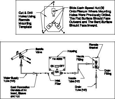
Clip the three speed nuts over the mounting holes as
shown in Figure 9.
9. Attach the Remote Nozzle Bracket to the plenum, using the three #8-15 x 1/2” long hex head sheet metal screws.
10. Locate a cold water line, upstream of any water softener, within 10 feet of the Remote Nozzle
Bracket Assembly. The line may be plastic, copper,
steel, iron or brass tubing or pipe and must
have an outside diameter of between 3/8” and 1-5/16”. If the nearest suitable line is
further than 10 feet away, 1/4” copper tube must be used instead of the plastic tubing supplied (contact Field Controls Technical
Support for assistance if needed).
11. Carefully following the instructions printed on the Saddle Valve Assembly bag, attach
the saddle valve to the water line. (See Figure 10)
12. Attach one 10’ section of the supplied plastic tubing to the saddle valve and the
inlet connection of the Housing Assembly,
as shown in Figure 10, using the inserts, sleeves and nuts found in the saddle valve bag, and cutting to length as necessary.
CAUTION: To avoid overtightening of the fittings use caution. Only use enough force to “snug up” the fitting nuts, then turn nut half a turn more.
13.Attach another 10’ section of plastic tubing to the Housing Assembly’s outlet connection and the Remote Nozzle Bracket’s nozzle fitting.
14.Attach the remaining 10’ section to the drain fitting on the Remote Nozzle Bracket and fix the other end to an open drain or receptacle (a coffee can will do), or route outdoors. Maintain a downward slope of at least 1” of drop per foot of tubing if possible; cut the tubing to length as necessary. IT IS IMPORTANT THAT THE END OF THE DRAIN TUBE BE AT LEAST 10” LOWER THAN THE NOZZLE DRAIN FITTING. DO NOT CONNECT THE DRAIN TUBE TO A DRAIN PIPE OR VENT. THE END OF THE DRAIN TUBE MUST REMAIN FREE OF INSECTS, DIRT, AND OTHER BLOCKAGE AND BE FREE TO DRAIN AT ALL TIMES.
15.Slowly open the saddle valve, turning the handle counterclockwise, and check all connections for leaks. If any leaks are observed, tighten the fitting nut until the leak stops. Make sure the saddle valve is fully open.
16.Strip approximately 1/2” of insulation from the ends of both red and white wires at one end of the power supply cable.
17.Using an electrical crimper or pliers, securely crimp on a quick connect terminal (supplied) to each of the red and white wires.
18.Plug both of the terminals into the bushing terminals on the side of the Housing Assembly as shown in Figures 1-3 & 5. Turn the Housing Assembly power switch to the “OFF” position.
19.Route the power cable to a nearby 115 volt outlet and cut to length if necessary. If a longer cable is needed, contact Technical Support or use 18 gauge 2-conductor thermostat wire purchased locally.
20.Strip the ends of both red and white wires in the cable as before.
21.Firmly attach the red wire to either of the screw terminals on the 120/24 VAC transformer, and the white wire to the other terminal on the transformer.
22.Make certain the Housing Assembly’s power switch is “OFF,” and plug the transformer into the outlet. The transformer should now be supplying 24 volts AC to the TM-2000.
Page 4
HUMIDIFIER ADJUSTMENT
The TM-2000 must now be adjusted so that it activates after heated air circulation begins, and de-activates before the heated air circulation ends.
1.Turn the adjustment knob on the Housing Assembly to the lowest sensitivity setting (fully clockwise). Set the Housing Assembly power switch to the “ON” position. THE TM-2000 SHOULD NOT ACTIVATE AT THIS TIME.
2.Set the furnace thermostat to cause continued operation of the furnace.
3.At approximately 2 minutes after the furnace begins blowing heated air through the ductwork, turn the adjustment knob counterclockwise just until the TM-2000 activates. This will be indicated by glowing of the “ON” light on the Housing Assembly.
4.Lower the thermostat to end the furnace heating cycle. Check to be sure the TM-2000 deactivates at least 30 seconds before the furnace stops blowing air through the ductwork. If the TM-2000 does not deactivate soon enough, turn the adjustment knob slightly clockwise.
5.Check the operation of the TM-2000 for several more heating cycles to be sure of proper operation as described above, and adjust the TM-2000 as necessary. If proper operation cannot be obtained, call Field Controls Customer Service at (252) 522-3031 for further assistance.
6.Once proper adjustment has been made, humidity levels can be increased or decreased by small adjustments of the TM-2000. Always verify proper operation as described above, after any adjustment has been made.
7.Inspect the system for leaks, loose wires, etc. SEVERAL DROPS OF WATER PER HEATING CYCLE FROM THE DRAIN TUBE ARE NORMAL. IF SIGNIFICANTLY MORE IS OBSERVED, CALL FIELD CONTROLS CUSTOMER SERVICE, OR CONSULT THE TROUBLESHOOTING GUIDE IN THIS MANUAL.
WHEN HUMIDIFICATION IS REQUIRED
1.Plug the transformer into the receptacle.
2.Open the saddle valve completely.
3.Place the "ON/OFF" switch in the "ON" position.
4.Check for proper sequence of operation by setting thermostat to call for heat and follow through complete cycle.
NOZZLE CAPACITY CHART
Table 1
|
NOZZLE |
|
|
PART |
|
|
|
|
|
|
HEATED |
|
|
|
|
||
|
|
|
|
|
GAL/DAY |
|
|
FLOOR |
|
|
STD/OPT |
|
|||||
|
SIZE |
|
|
NUMBER |
|
|
|
|
|
|
|
||||||
|
|
|
|
|
|
|
|
|
SPACE |
|
|
|
|
||||
|
|
|
|
|
|
|
|
|
|
|
|
|
|
|
|
||
0.65 |
|
|
46017401 |
|
UP TO 9 |
|
|
UP TO |
|
|
STANDARD |
|
|||||
|
|
|
|
3000 |
|
|
|
|
|||||||||
|
GPH |
|
|
|
|
|
|
|
|||||||||
|
|
|
|
|
|
|
|
|
|
SQ. FT. |
|
|
|
|
|||
|
|
|
|
|
|
|
|
|
|
|
|
|
|
|
|
||
1.00 |
|
|
|
|
|
|
|
|
|
|
UP TO |
|
|
|
|
||
|
|
46017402 |
|
UP TO 12 |
|
4000 |
|
|
|
OPTIONAL |
|
||||||
|
GPH |
|
|
|
|
|
|
|
|||||||||
|
|
|
|
|
|
|
|
|
|
SQ. FT. |
|
|
|
|
|||
|
|
|
|
|
|
|
|
|
|
|
|
|
|
|
|
||
1.35 |
|
|
|
|
|
|
|
|
|
|
UP TO |
|
|
|
|
||
|
|
46017403 |
|
UP TO 18 |
|
5000 |
|
|
|
OPTIONAL |
|
||||||
|
GPH |
|
|
|
|
|
|
|
|||||||||
|
|
|
|
|
|
|
|
|
|
SQ. FT. |
|
|
|
|
|||
|
|
|
|
|
|
|
|
|
|
|
|
|
|
|
|
||
ELECTRICAL RATING |
|
|
|
|
|
|
|
|
|
|
|||||||
Table 2 |
|
|
|
|
|
|
|
|
|
|
|
|
|
|
|||
|
|
|
|
|
|
|
|
|
|
|
|
||||||
|
VOLTS |
|
AMPS |
|
|
VA |
|
|
|
Hz |
|
||||||
|
24 VAC |
|
0.40 |
|
10 |
|
60 |
|
|||||||||
Page 5
MAINTENANCE
PERIODIC
The TM-2000 humidifier requires little maintenance, however it is important to follow these recommendations.
1.Water quality varies considerably across the country. The water inlet filter, and spray atomizing nozzle may become clogged during operation. The frequency of this occurrence will depend on the quality of your water. The spray characteristics should be checked periodically to verify that a fine mist is being produced. During a normal operating cycle, remove the remote bracket (leave the speed nuts in place on the plenum). Verify that a fine mist is being produced when the TM-2000 has been activated by the warm air flow.
2.If the spray is weak or comes out in a narrow stream, it is an indication that the nozzle and inlet filter must be replaced. Neither of these parts can be cleaned without causing damage which will impair humidifier operation. Use only genuine Field Controls replacement parts. Replace the nozzle and inlet filter as often as necessary.
CAUTION: Close the saddle valve completely and disconnect the transformer from the receptacle prior to any service to the TM-2000.
3.To replace the nozzle, unscrew it from the nozzle adapter by securely holding the nozzle adapter with one wrench and loosen the nozzle with a separate wrench. Replace with a new nozzle using Teflon tape or other pipe thread sealant on the male pipe threads.
4.Replace the remote bracket onto the plenum as it had originally been attached.
5.To replace the water inlet filter, it is necessary to first remove the water supply tube from the water inlet fitting. Screw a small screw into the existing filter, and then pull the screw outward. This will pull out the filter element, which will allow the replacement with a new element. Then re-attach the water supply tube to the water inlet fitting.
6.Open the saddle valve completely and place the "ON/OFF" switch in the "ON" position.
SEASONAL
At the conclusion of the heating season, the following steps should be taken to ensure proper performance when humidification is desired once again.
1.Close the saddle valve completely.
2.Place the "ON/OFF" switch in the "OFF" position and disconnect the transformer from the receptacle.
3.Disconnect and drain the plastic tubing from the saddle valve to the water inlet, and from the water outlet to the remote bracket (nozzle inlet).
4.Check the drain tube connected to the remote bracket to ensure that it is empty.
5.Remove the remote nozzle bracket from the plenum, and replace the nozzle following the previously described procedure.
6.Replace the water inlet filter following the previously described procedure.
7.Remount the remote bracket to the plenum and re-connect the plastic tubing, while leaving the saddle valve closed, and transformer disconnected.
TROUBLESHOOTING GUIDE
Refer to the previous sections for optional suggestions and control components which may be required. The components include a Humidistat and an Air Booster Activator. The Humidistat will allow power supply to the TM-2000 only when there is a call for humidity. The TM-2000 will still be activated only by the warm air flow. The Air Booster Activator recognizes when the blower is on and supplies power to the TM-2000 only during this time. This can be used to prevent TM-2000 operation when the blower is off.
1.TM-2000 will not come on.
a.Check electrical receptacle for power.
b.Check air flow temperature within the plenum. If not 120o F, adjust furnace blower "ON" to a higher temperature, or attempt to locate a position which will satisfy the temperature requirement.
2.TM-2000 comes on after furnace blower shuts off or TM-2000 remains on after blower shuts off.
a.Install an optional Air Booster Activator to prevent TM-2000 operation when the blower is off.
b.The furnace blower controls can be adjusted to ensure that the blower operates for a longer period of time, or the TM-2000 can be electrically interconnected to the furnace blower motor circuit.
3.A light dust appears on furniture, registers, etc.
a.Some areas have high calcium, and mineral content in the water supply. The dust created as the water evaporates will not adversely affect any household effects. The problem can be minimized by installing an in-line water filter in the water supply line. The filter should be of the type which uses replaceable cartridges. Check your local hardware store.
Page 6
 Loading...