


24 VAC SYSTEM CONTROL KIT
Model: CK-43
Tubing
MG1 Barometric
Draft Control
The CK-43 is designed for use with the SWG Series Power Venter for controlling Natural Gas and L.P. Gas Draft Induced appliances.
Control kits control the operation of SWG Power Venters. Control
Kits can also control the operation of Field Draft Inducers and
Combustion Air Systems.
ITEMS INCLUDED IN KIT
1)Junction box with mounted pressure switch and relay/timer.
1) 1 Ft. Length of 1/4 inch aluminum tubing.
1) 1/4 inch tubing connector
1) Flexible conduit connector
1)4" MG1 Barometric Draft Control or 5" AF Barometric Draft Control
This device MUST be installed by a qualified agency in accordance with the manufacturers installation instructions.
The definition of a qualified agency is: any individual, firm, corporation or company which either in person or through a representative is engaged in, and is responsible for, the installation and operation of gas appliances, who is experienced in such work, familiar with all the precautions required, and has complied with the requirements of the authority having jurisdiction.
DO NOT DESTROY
THESE INSTRUCTIONS MUST REMAIN WITH EQUIPMENT
2630 Airport Road · Kinston, NC 28504
Phone: 252-522-3031· Fax: 252-522-0214
www.fieldcontrols.com
INSTALLATION INSTRUCTIONS
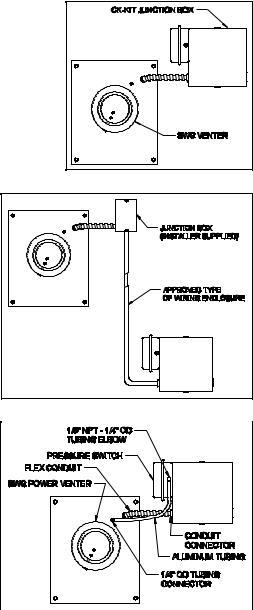
MOUNTING JUNCTION BOX
The junction box can be mounted at the venter or remotely mounted away from the venter. (See Figure 1 & Figure 2)
1.Remove one of the knockouts from the side of the junction box where the pressure switch is mounted. Install the flexible conduit connector onto the
CK-43 junction box and secure with fastening nut. If remote mounting the CK-43 junction box, mount the flexible conduit connector onto a 2" x 4" installer supplied junction box.
2. Fasten the flexible conduit from the SWG Venter into the conduit connector. Mount the CK-43 junction box or installer supplied junction box onto the wall or floor joist without straining the flexible conduit. Fasten the CK-43 junction box through the four dimpled locations on the base of the box. (See Figure 3)
PRESSURE SWITCH SENSING TUBE INSTALLATION
1.Attach the 1/4 inch tubing connector to the pressure tube on the SWG Venter. (See Figure 3)
2.Connect the supplied 1/4" aluminum tubing to the tubing connector. Route the tubing to the CK-43 junction box and
connect the tubing to the pressure switch. When routing the tubing, avoid kinking the tubing by bending the tubing too sharply.
For remote mounted CK-43 Junction Box, use a 1/4" OD copper, aluminum or plastic tubing and route the tubing to avoid contact with any heat source.
Figure 1
Figure 2
Figure 3
Page 2
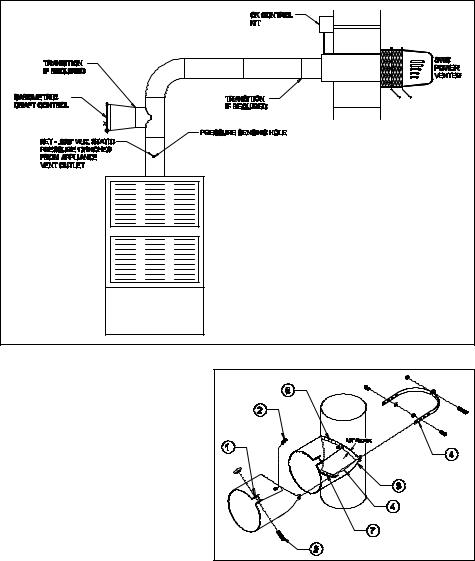
DRAFT CONTROL INSTALLATION
See Figure 4 for typical vent system layout.
CAUTION: This draft control is shipped as a single acting draft control. If the draft control is not being used on a gas draft induced furnace, remove the gate stop on the draft control ring before installing.
COLLAR INSTALLATION
This control is shipped with a collar patterned to fit a single wall round vent pipe. To attach this collar to the flue, see Figure 5 and follow the instructions below.
1.Bend outward the two ears at the front corners of the collar. Bend 90 degrees, 1/4 inch behind the single hole on the
straps.
2. Insert clamping screw in ears on collar and bolt the remainder of the collar together.
3. Hold the collar against the side of the flue in the exact position it is to be installed (shown by dotted lines) and mark the outline of the collar on the flue.
4.Cut a hole in the flue about 1/2" inside of this outline.
5.Make a series of cuts about 1/2" apart from the edge of this hole to the outline marks.
Figure 4
Figure 5
6.Strap the collar to the flue pipe.
7.Bend the tabs formed by the series of cuts outward against the inside of the collar to make a tight joint.
8.Refer to Insertion of Draft Control Section.
Page 3
 Loading...