


POWERED MIXERS
|
|
|
3 |
|
|
From Fender Pro Audio8 |
|
|
|
|
/ |
6 |
3 |
0 |
2 |
|
|||
|
|
||
|
|
|
|
0 |
2 |
|
Owner's Manual for SRM 6302 / 8302
P/N 050804
REV A

Fender Musical Instruments
7975 North Hayden Road, Scottsdale, Arizona 85258 U.S.A.
Fender knows the importance of sound reinforcement. From the simple box-top mixer to today's professional touring concert systems, the need to communicate, to make the connection between the performer and the audience is foremost in Fender's mind.
Perhaps no other single piece of gear can make or break your band's sound. You see, your sound system is more than just a combination of dials, wires and speakers. It is an integral part of the audio chain and should be treated with special care and attention to detail.
At Fender, we know what building quality musical instruments and sound reinforcement equipment is all about. In fact, many of the world's best sounding electric musical instruments and sound reinforcement equipment proudly wear the Fender name.
Whether you need a simple box top powered mixer for your Saturday afternoon jam, or a professional full-size concert system, Fender has the sound reinforcement equipment to meet your needs. Likewise, your decision to purchase Fender pro audio gear is one you will appreciate with each performance for years to come.
Wishing you years of enjoyment and a heartfelt thank you,
Bill Schultz
Bill Schultz
Chairman
Fender Musical Instruments Corporation

SRM 6302 / 8302
PROFESSIONAL POWERED
MIXER
INTRODUCTION
150 Watts per Channel at 4Ω
Assignable Dual Power Amplifiers
9-Band Assignable Graphic Equalizer with 30mm Sliders
3-Band Equalizer per Input Channel
+48V DC Phantom Power
Individual Channel Effects Level Control
Both 1/4 inch Phone TRS and 3-Pin XLR Female Input Connectors
Patch Points for Line Level Output and Power Amp Inputs and Outboard Gear
Full-bodied Spring Reverb
The SRM 6302 / 8302: a dual 150 watt professional powered mixer from your friends at Fender® Pro Audio. We are sure you will find your new SRM 6302 / 8302 to be both a unique and effective sound reinforcement product, providing years of trouble-free service.
With ease of setup in mind, the integrated mixer/amplifier design of your SRM 6302 / 8302 makes it a complex and versatile unit, yet simple to operate. Enclosed in a boxtop style cabinet, your SRM 6302 / 8302 features individual channel preamps, an assignable dual power amplifier, +48V DC phantom power, a 9-band graphic equalizer, line and mic level channel inputs, a patch bay and much, much more. With 1/4 inch TRS phone jacks, 3-Pin XLR female input jacks and stereo RCA input jacks, your SRM 6302 / 8302 can accommodate almost any input connection and signal level.
Ideal for live music, churches, auditoriums, hotel conference or meeting rooms, your SRM 6302 / 8302 is suitable for a wide variety of sound reinforcement applications. With its assignable dual power amplifier, your SRM 6302 / 8302 can feed your main front of house speakers while simultaneously providing power for stage monitors. Its front panel patch bay makes using outboard effects gear and signal processing equipment a snap. Moreover, the patch bay provides easy access for adding or rerouting power amplifiers.
Designed to meet the most demanding needs of audio professionals, your SRM 6302 / 8302 will provide years of reliable, trouble-free service, day in and day out. Please read through this owner’s manual in order to more thoroughly understand the operation of your SRM 6302 / 8302.
WARNING:
-TO REDUCE THE RISK OF FIRE OR SHOCK HAZARD, DO NOT EXPOSE THIS UNIT TO RAIN OR MOISTURE.
-NO USER SERVICEABLE PARTS INSIDE, REFER SERVICING TO QUALIFIED PERSONNEL ONLY.
-ALLOW AT LEAST 3” (7.6 cm) AROUND THE UNIT FOR PROPER VENTILATION.
-THIS UNIT MUST BE EARTH GROUNDED.
3

INPUT CHANNEL CONTROL FUNCTIONS
A
0


 MAX
MAX
EFFECTS
B
15
 +15
+15
HIGH
A.EFFECTS - This knob controls the amount of signal its respective channel sends to the overall effects mix. When the knob is set at 0, the output is “dry”.
B.HIGH - Adjusts the amount of high frequency boost or cut in the channel. When all the tone controls are set at 0 (straight up), the channel is “flat” with no frequencies cut or boosted.
|
C |
C. MID - Adjusts the amount of |
|
|
middle frequency boost or cut in |
15 |
+15 |
the channel. |
|
||
|
MID |
D. LOW - Adjusts the amount of |
|
D |
low frequency boost or cut in the |
|
channel. |
15
 +15
+15
LOW
E
0 |
MAX |
MONITOR
F
0


 MAX
MAX
LEVEL
E.MONITOR - This knob controls the amount of signal its respective channel sends to the monitor mix. When the knob is set at 0, the channel’s signal is not sent to the monitor bus.
F.LEVEL - Adjusts the volume control of the individual channel. Rotating the knob clockwise increases the respective channel’s contribution to the “Main Out” mix. Adjust this control after the MAIN or overall volume of the SRM 6302 / 8302 has been set.
INPUT CHANNEL CONNECTIONS
G. LINE - Plug your instrument in  G here. This 1/4 inch TRS balanced
  input jack suited for use with items
|
|
|
|
|
|
having a line level output such as |
||
LINE |
high impedance microphones, |
|||||||
keyboards, |
drum |
machines, |
||||||
|
|
|
H |
outboard effects, etc. |
It accepts |
|||
|
|
|
|
|
|
both balanced and unbalanced |
||
|
|
|
|
|
|
|||
|
|
|
|
|
|
cables |
|
|
|
|
|
|
|
|
H. MIC - Plug your microphone in |
||
|
|
|
|
|
|
here. This three pin XLR balanced |
||
|
|
|
|
|
|
|||
|
|
|
|
|
|
female input connector is intended |
||
MIC |
||||||||
|
|
|
|
|
|
for input |
signals |
from low |
impedance microphones. Pins 2 and 3 provide Phantom Power (+48V DC) for condenser style microphones when the phantom power switch is on.
PATCH BAY PANEL CONNECTIONS
I |
K |
M |
MAIN OUT |
MON OUT |
EFFECTS OUT/ |
|
|
FOOTSWITCH |
J |
L |
N |
PA 1 IN |
PA 2 IN |
EFFECTS IN |
I.MAIN OUT - This 1/4 inch, TS, unbalanced, line level output is designed to feed the SRM 6302 / 8302’s main bus signal to an external power amplifier or main house mixer.
J.PA 1 IN - This 1/4 inch, TS, unbalanced, line level input jack allows the SRM 6302 / 8302’s power amplifier #1 (PA 1) to be fed from an external signal source. When this connection is used, the “main out” connection to PA 1 is overridden.
K.MON OUT - This 1/4 inch, TS, unbalanced, line level output is designed to feed the SRM 6302 / 8302’s monitor bus signal to an external power amplifier or monitor system.
L.PA 2 IN - This 1/4 inch, TS, unbalanced, line level input jack allows the SRM 6302 / 8302’s power amplifier #2 (PA 2) to be fed from an external signal source. When this connection is used, the internal connection to PA 2 is overridden.
M.EFFECTS OUT/FOOTSWITCH - This 1/4 inch, TS, unbalanced, line level output jack is designed to feed the SRM’s effects bus signal to an external signal processing device, such as a digital delay or a chorus unit. When a footswitch (P/N 048458, optional) is inserted into this jack, the SRM’s internal reverb can be turned on or off remotely.
N.EFFECTS IN - This 1/4 inch, unbalanced, TS, line level input jack is designed to accept signal from an external processing device, such as a digital delay or a chorus unit. The signal entering this jack is mixed into the Main and Monitor using the “Tape/Effects” controls labeled “Return to Main” and “Return to Monitor”.
4
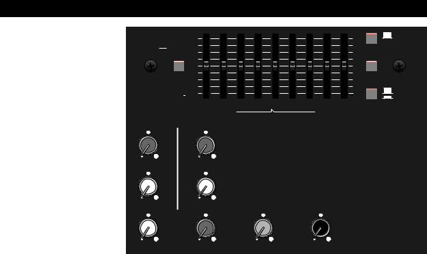
MASTER CONTROL PANEL FUNCTIONS
A. EQ ASSIGN - This button switches the graphic equalizer between the main and the monitor bus. When this button is pressed, the EQ is assigned to the monitor bus.
+12dB
 MAIN
MAIN
 MON
MON
A OdB
EQ ASSIGN
+12dB |
OFF |
C |
|
 ON
ON
PHANTOM POWER
OdB D
POWER
|
|
|
|
12dB |
|
|
|
|
|
|
12dB |
MAIN |
|
B. GRAPHIC EQUALIZER - |
|
|
125 |
250 500 |
1k |
2k |
4k |
8k |
MON E |
||||
|
|
63 |
16k |
||||||||||
|
|
|
|
|
|
|
|
|
|
|
|
||
This 9 band graphic equalizer |
|
|
|
B GRAPHIC EQUALIZER |
|
PA 2 ASSIGN |
|||||||
|
|
|
|
|
|
||||||||
consists of active band pass |
TAPE/ |
REVERB |
|
|
|
|
|
|
|
||||
/ band reject filters spaced at |
EFFECTS |
|
I |
|
|
|
|
|
|
|
|||
octave intervals. |
Moving the |
|
F |
|
|
|
|
|
|
|
|
||
sliders up or down boosts or |
|
|
|
|
|
|
|
|
|
|
|
||
cuts the gain at the indicated |
0 |
MAX |
0 |
MAX |
|
|
|
|
|
|
|
||
RETURN |
RETURN |
|
|
|
|
|
|
|
|||||
frequency. |
|
TO MONITOR |
TO MONITOR |
|
|
|
|
|
|
|
|||
|
|
G |
|
J |
|
|
|
|
|
|
|
||
C. PHANTOM POWER - |
|
|
|
|
|
|
|
|
|
||||
|
|
|
|
|
|
|
|
|
|
|
|||
When this button is pressed, |
0 |
MAX |
0 |
MAX |
|
|
|
|
|
|
|
||
a +48V DC Phantom Power |
RETURN |
RETURN |
|
|
|
|
|
|
|
||||
TO MAIN |
TO MAIN |
|
|
|
|
|
|
|
|||||
supply is activated, necessary |
|
H |
|
K |
|
L |
|
|
M |
|
|||
for some condenser style |
|
|
|
|
|
|
|
|
|
|
|
||
microphones. |
Before |
0 |
MAX |
0 |
MAX |
0 |
MAX |
0 |
|
MAX |
|
||
plugging or unplugging any |
|
MAIN |
MONITOR |
EFFECTS |
|
REC OUT |
|
||||||
|
|
|
|
|
|
|
|
|
|
|
|||
microphone, make sure the |
|
|
|
|
|
|
|
|
|
|
|
||
Phantom Power supply is off. |
|
|
|
I. REVERB RETURN TO MONITOR - |
Adjusts the |
||||||||
|
|
|
|
|
|||||||||
D. POWER LED - This LED illuminates when the |
amount of reverb signal level sent to the monitor mix. |
||||||||||||
Rotating the knob clockwise increases the reverb |
|||||||||||||
SRM 6302 / 8302 is on. |
|
|
|
||||||||||
|
|
|
signal sent to the monitor mix. When the knob is set |
||||||||||
E. PA 2 ASSIGN - This button switches the second |
|||||||||||||
at 0, the output is “dry”. |
|
|
|
||||||||||
power amplifier between the main and the monitor bus. |
|
|
|
|
|
|
|
|
|||||
When this button is pressed, the second power |
J. REVERB RETURN TO MAIN - |
Adjusts the |
|||||||||||
amplifier is assigned to the monitor bus providing |
amount of reverb signal level sent to the main mix. |
||||||||||||
power to drive monitor speakers. When this button is |
Rotating the knob clockwise increases the reverb |
||||||||||||
in the Main position, the second power amplifier is |
signal sent to the main mix. When the knob is set at |
||||||||||||
assigned to the main bus providing additional power for |
0, the output is “dry”. |
|
|
|
|
||||||||
front of house enclosures. When connecting the |
K. MONITOR - The monitor output volume control |
||||||||||||
speakers to your SRM 6302 / 8302, connect one |
|||||||||||||
cabinet to the PA 1 Out jack and the other to the PA 2 |
of the SRM 6302 / 8302. |
|
Any adjustments to this |
||||||||||
Out jack. |
|
|
|
|
control will affect the signal level at the Mon Out, as |
||||||||
F. TAPE/EFFECTS RETURN TO MONITOR - |
well as, PA1 and PA2 depending upon the PA2 |
||||||||||||
Assign switch position and patch bay configuration. |
|||||||||||||
Adjusts the tape/effects signal level sent to the |
L. EFFECTS - |
Adjusts the signal level present at the |
|||||||||||
monitor mix from either the Effects In or Tape In jacks. |
|||||||||||||
Rotating the knob clockwise increases the tape/effects |
Effects Out / Footswitch jack, as well as, the signal |
||||||||||||
signal sent to the monitor mix. |
|
|
|
driving the reverb. |
Rotating the knob clockwise |
||||||||
G. TAPE/EFFECTS RETURN TO MAIN - |
Adjusts |
increases the amount of tape/effects and reverb drive |
|||||||||||
signal. When the knob is set at 0, there is no effects |
|||||||||||||
the tape/effects signal level sent to the main mix from |
drive signal. |
|
|
|
|
|
|
||||||
either the Effects In or Tape In jacks. Rotating the |
M. REC OUT - Adjusts the tape out signal level of |
||||||||||||
knob clockwise increases the tape/effects signal sent |
|||||||||||||
to the main mix. |
|
|
|
|
the SRM 6302 / 8302. (The Main Out signal feeds |
||||||||
H. MAIN - The main output volume control of the |
this control.) |
Rotating the knob clockwise increases |
|||||||||||
the output level. When the knob is set at 0, there is |
|||||||||||||
SRM 6302 / 8302. Any adjustments to this control |
no signal level output. |
|
|
|
|
||||||||
will affect the signal level at the Main Out, as well as, |
|
|
|
|
|
|
|
|
|||||
PA1 and PA2 depending upon the PA2 Assign |
|
|
|
|
|
|
|
|
|||||
switch position and patch bay configuration. |
|
|
|
|
|
|
|
|
|
||||
5
 Loading...