


Falmec F3GI10S1, F3GV12S1-ER2010, F3GV12S1-EW2010, F3MLD12S1-ER1140, F3MLD12S1-EW1140 User Manual
...

CONGRATULATIONS
Congratulations and thank you for choosing a Falmec rangehood.
To avoid the risks that are always present when you use an electrical appliance it is important that the rangehood is installed correctly and that you read the safety instructions carefully to avoid misuse and hazards.
We recommend that you keep this instruction booklet for future reference and pass it on to any future owners.
Important Information
AFTER UNPACKING THE RANGEHOOD PLEASE REVIEW YOUR NEW ITEM TO ENSURE THAT IT HASN’T BEEN DAMAGED IN TRANSIT OR IS MISSING ANY COMPONENTS. FAILURE TO REPORT ANY ISSUE WITHIN 72 HOURS OF RECEIPT OF YOUR ITEM MAY RESULT IN ADDITIONAL CHARGES.
Environmental Tip
Information on disposal for users
Most of the packing materials are recyclable. Please dispose of those materials through your local recycling depot or by placing them in a appropriate collection bin.
TO AVOID THE RISK OF INJURY OR DAMAGE TO THE PRODUCT IT IS ESSENTIAL TO READ THESE INSTRUCTIONS PRIOR TO
If you wish to discard this product, please contact |
INSTALLATION AND USE |
your local authorities and ask for the correct method |
|
of disposal. |
|

PRODUCT DESCRIPTION & CARTON CONTENTS
CARTON 1 - HOOD UNIT
You will be supplied with one of the three hood unit options detailed below.
OPTION 1 - INTEGRATED HOOD - ON BOARD HOOD
Models include:
SIENA F3SN60S1, F3SN90S1 and F3SND90S1
Included in the carton:
1.Main hood housing including control module and lighting
2.Baffle filters
3.Grease trap
4.Fixing screws
5.Operating & installation guide
OPTION 2 - INTEGRATED HOOD - REMOTE MOTOR
Models include:
MILANO F3ML60S1, F3ML90S1, F3MLD90S1, F3MLD12S1 and GENOVA F3GV12S1
Included in the carton:
1.Main hood housing including control module and lighting
2.Baffle filters
3.Grease trap
4.Fixing screws
5.Operating & installation guide
OPTION 3 - WALL HUNG CANOPY - REMOTE MOTOR
Models include:
LATINA F5LT90S1, MODENA F5ME12S1 and TRENTO F5TN12S1
Included in the carton:
1.Main hood housing including control module and lighting
2.Baffle filters
3.Flue cover x2
4.Fixing screws
5.Operating & installation guide
OPTION 4 - ISLAND HUNG CANOPY - REMOTE MOTOR
Models include:
TREVISO F7TV90S1 and ROMA F7RM90S1
Included in the carton:
1.Main hood housing including control module and lighting
2.Baffle filters
3.Flue cover x2
4.Island mounting bracket
5.Fixing screws
6.Operating & installation guide
PRODUCT DESCRIPTION & CARTON CONTENTS
CARTON 2 - FAN MOTOR UNIT
You will be supplied with one of the two fan motor options detailed.
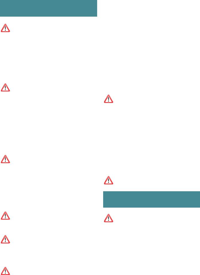
OPTION 1 - IN ROOF SOLUTION (FIG.4a)
Models include:
IR-765 and IR-1140 Unit designed to be located in a roof space and then ducted to an external vent.
Included in the carton:
1.In Roof Motor Unit
2.Mounting Bracket
3.Fixing Screws
4.Duct Clamps x4
5.200 mm Flexi Duct (5 Meters Length)
6.White Stainless Steel Eave Vent
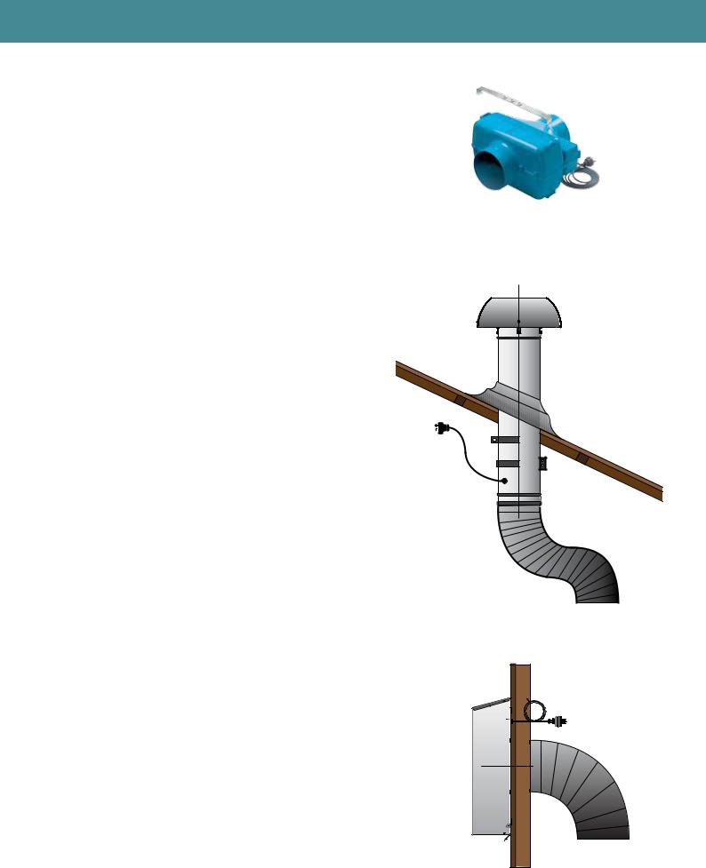
OPTION 2 - EXTERNAL ROOD SOLUTION (FIG.4b)
Models include:
ER-765, ER-1140 and ER-2010
Unit designed to be mounted externally penetrating through the roof.
Included in the carton:
1.External Roof Motor Unit
2.Duct Calmps (x2)
3.200mm Flexi Duct (5 Meters Length)
OPTIONAL ACCESSORIES WHEN ROOF MOUNTING
1.200 mm Tile Roof Install Kit (HBX200TILE)
Includes roof flashing for tile roof and mounting brackets x2
2.200 mm Metal Roof Install Kit (HBX200MET)
Includes roof flashing for metal roof and mounting brackets x2
OPTION 3 - EXTERNAL WALL SOLUTION (FIG.4c) |
|
Models include: |
|
EW-765, EW-1140 and EW-2010 |
|
Unit designed to be mounted directly on an external wall. |
|
Included in the carton: |
|
1. External Wall Motor Unit |
|
2. Duct Clamps x 2 |
|
3. 200 mm Flexi Duct (5 Meters Length) |
(FIG.4a) |
|
(FIG.4a)
(FIG.4b)
(FIG.4c)
SAFETY INSTRUCTIONS
AND WARNINGS
Installation operations are to be carried out by skilled and qualified installers in accordance with the instructions in this booklet and in compliance with the regulations in force.
DO NOT use the hood if the power supply cable or other components are damaged: disconnect the hood from the electrical power supply and contact the Dealer or an authorised Servicing Dealer for repairs.
Do not modify the electrical, mechanical or functional structure of the equipment.
Do not personally try to carry out repairs or replacements. Interventions carried out by incompetent and unauthorised persons can cause serious damage to the unit or physical and personal harm, not covered by the Manufacturer’s warranty.
WARNINGS FOR THE INSTALLER
TECHNICAL SAFETY
Before installing the hood, check the integrity and function of each part. Should anomalies be noted, do not proceed with installation and contact the Dealer.
Do NOT install the hood if an aesthetic (or cosmetic) defect has been detected. Put it back into its original package and contact the dealer.
No claim can be made for aesthetic (or cosmetic) defects once it has been installed.
During installation, always use personal protective equipment (e.g.: Safety shoes) and adopt prudent and proper conduct.
The installation kit (screws and plugs) supplied with the hood is only to be used on masonry walls: in case of installation on walls of a different material, assess other installation options keeping in mind the type of wall surface and the weight of the hood (indicated on page 2).
Keep in mind that installations with different types of fastening systems from those supplied, or which are not compliant, can cause electrical and mechanical seal danger.
Do not install the hood outdoors and do not expose it to atmospheric elements (rain, wind, etc.).
ELECTRICAL SAFETY
The electrical system to which the hood is to be connected must be in accordance with local standards and supplied with earthed connection in compliance with safety regulations in the country of use. It must also comply with European standards regarding radio antistatic properties.
Before installing the hood, check that the electrical mains power supply corresponds with what is reported on the identification plate located inside the hood.
The socket used to connect the installed equipment to the electrical power supply must be within reach: otherwise, install a mains switch to disconnect the hood when required.
Any changes to the electrical system must be carried out by a qualified electrician.
The maximum length of the flue fastening screws (supplied by the manufacturer) must be 13 mm. Use of non-compliant screws with these instructions can lead to danger of an electrical nature.
Do not try to solve the problem yourself in the event of equipment malfunction, but contact the Dealer or an authorised Servicing Department for repairs.
When installing the hood, disconnect the equipment by removing the plug or switching off the main switch.
FUMES DISCHARGE SAFETY
Do no connect the equipment to discharge pipes of fumes produced from combustion (for example boilers, fireplaces, etc.).
Before installing the hood, ensure that all standards in force regarding discharge of air out of the room have been complied with.
USER WARNINGS
These warnings have been drawn up for your personal safety and those of others. You are therefore kindly asked to read the booklet carefully in its entirety before using the or cleaning the equipment.
The Manufacturer declines all responsibility for any damage caused directly, or indirectly, to persons, things and pets as a consequence of failing to comply with the safety warnings indicated in this booklet.
It is imperative that this instructions booklet is kept together with the equipment for any future consultation.
If the equipment is sold or transferred to another person, make sure that the booklet is also supplied so that the new user can be made aware of the hood’s operation and relative warnings.
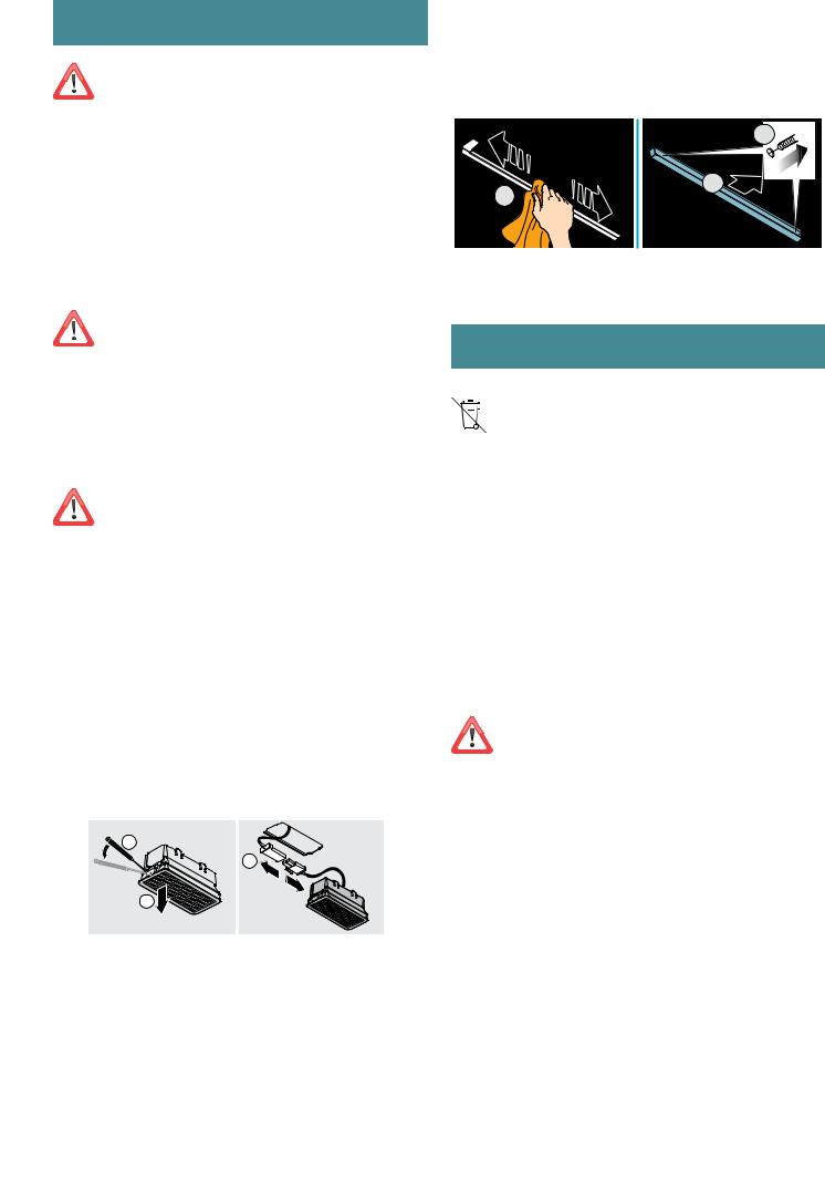
After the stainless steel hood has been installed, it will need to be cleaned to remove any residues remaining from the protection adhesive as well as any grease and oil stains which, if not removed, can cause irreversible damage to the hood surface. To properly clean the unit, the manufacturer recommends using the supplied moist wipes, which are also available sold separately.
Insist on original spare parts.
INTENDED USE
The equipment is solely intended to be used to extract fumes generated from cooking food in non-professional domestic kitchens: any other use is improper. Improper use can cause damage to persons, things, pets and exempts the Manufacturer from any liability.
The equipment can be used by children over the age of 8 and by persons with reduced physical, sensory and mental abilities, or with no experience or knowledge, as long as they do so under supervision or after having received relative instructions regarding safe use of the equipment and understanding of the dangers connected to it.
Children are not to play with the equipment. Cleaning and maintenance by the user must not be carried out by children without supervision.
USE AND CLEANING WARNINGS
Before cleaning or carrying out maintenance operations, disconnect the equipment by removing the plug or switching off the main switch.
Do not use the hood with wet hands or bare feet.
Always check that all electrical parts (lights, extractor fan) are off when the equipment is not being used.
The maximum overall weight of any objects placed or hung (if applicable) on the hood must not exceed 1.5 Kg.
Always supervise the cooking process during the use of deep-fryers: Overheated oil can catch fire.
Do not leave open, unattended flames under the hood. Do not prepare food over an open flame under the hood.
Never use the hood without the metal anti-grease filters: in this case, grease and dirt will deposit in the equipment and compromise its operation.
Accessible parts of the hood can be hot when used at the same time as the cooking appliances.
Do not carry out any cleaning operations when parts of the hood are still hot.
There can be a risk of fire if cleaning is not carried out according to the instructions and products indicated in this booklet.
Disconnect the main switch when the equipment is not used for long periods of time.
If other appliances that use gas or other fuels are being used at the same time (boiler, stove, fireplaces, etc.), make sure the room where the fumes are discharged is well-ventilated, in compliance with the local regulations.
INSTALLATION
only intended for qualified personnel
Before installing the hood, carefully read the chapter “SAFETY INSTRUCTIONS AND WARNINGS”.
TECHNICAL FEATURES
The technical specifications are exhibited on the labels located inside the hood.
POSITIONING
The minimum distance between the highest part of the cooking equipment and the lowest part of the hood is indicated in the installation instructions.
Generally, when the hood is placed over gas cookers, the distance must be at least 65 cm (25.6’’). However, according to an interpretation of standard EN60335-2-31 dated 11-07-2002 of TC61 (sub-clause 7.12.1 meeting 15 agenda item 10.11), the minimum distance between the cooker and lower part of the hood can be reduced to the quota reported in the installation instructions.
Should the instructions for the gas cooker specify a greater distance, this must be taken into consideration.
Do not install the hood outdoors and do not expose it to outdoor environment (rain, wind, etc.).
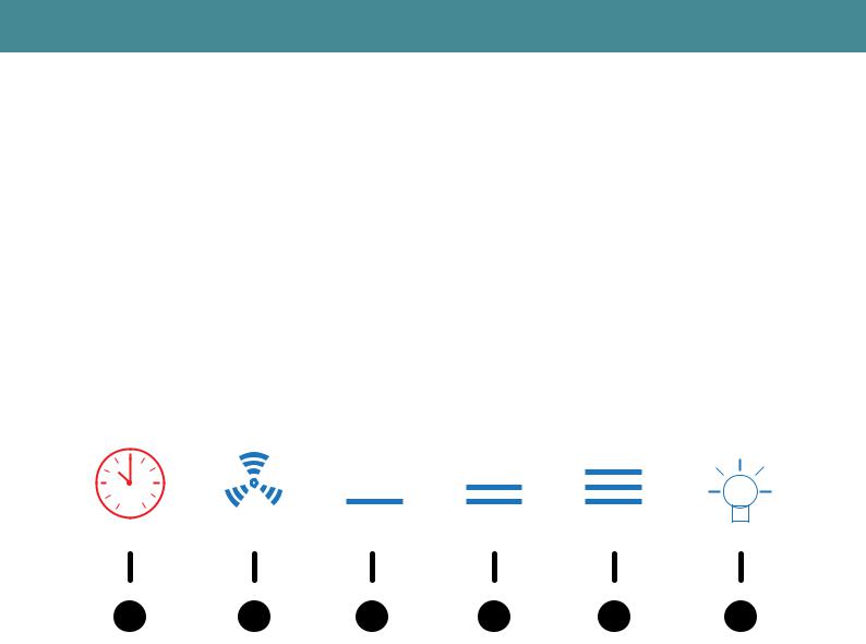
OPERATION
OPERATING YOUR CONTROL PANEL WITH THE 6 SENSOR TOUCH CONTROL
Turning the extraction function ON or OFF:
•In standby mode, press button 2 to turn on operating mode, then press buttons 3 through to 5 to change the speed.
•The hood has three speed options and a boost speed plus the off function.
•To turn hood off, press button 2 repeatedly until hood returns to standby mode.
Turning the light function ON or OFF:
Press button 6 to turn on or turn off the light in either standby mode or when the hood is in use. Light will remain on indefinitely until switched off using button 6 again, otherwise will switch off when time elapses in timer mode (when in use).
Turning the timer function ON or OFF:
In operating mode, press button 1 to engage the timer function.
The default time set is 15 minutes and cannot be increased or decreased.
24h
|
|
|
|
|
|
|
|
|
|
|
|
|
|
|
|
|
|
|
|
|
|
1 |
2 |
3 |
4 |
5 |
|
6 |
||||
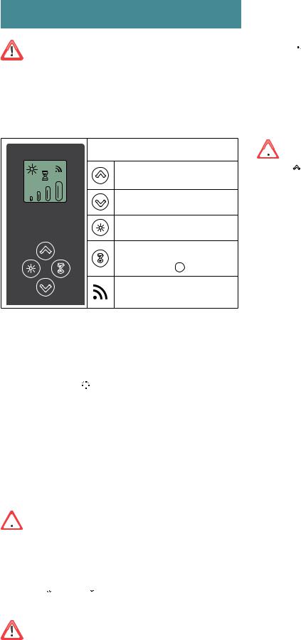
BUTTON 1:
TIMER (Red LED flashing)
Auto switch-off after 15 min.
The function deactivates (red LED off ) if:
-The motor turns off (key ).
-The speed is changed (keys +/-).
FILTER ALARM (red LED steady on)
Anti-grease filter maintenance after approximately 30 hours of operation. Press and hold the button for 3 seconds to reset.
BUTTON 2: Motor ON/OFF
Motor on/off and Speed1
If pressed for more than 3 seconds, it activates the 24h cycle (1h ON -> 3h OFF -> 1h ON)
BUTTON 3: Speed 2 activation
BUTTON 4: Speed 3 activation
BUTTON 5: Speed 4 activation for 10 minutes only
BUTTON 6: Light on/off
USIN THE RADIO CONTROL
WARNINGS!:
The radio control is optional.
Follow the entire procedure described below if purchased.
Place the hood away from sources of electromagnetic waves (e.g. microwave ovens), which could interfere with the radio control and with the hood electronics.
The maximum operating distance is 5 metres, that may vary according to the presence of electromagnetic interferences.
Radio control operated at 433.92MHz. The radio control consists of two parts:
-the receiver built into the hood;
-the transmitter shown here in the figure.
DESCRIPTION OF TRANSMITTING COM-
MANDS
UP
Motor switch-on and speed increase from 1 to 4. Speed 4 is only active for a few minutes.
DOWN
Speed decrease and motor switch-off
Light ON-OFF
TIMER ON: The motor automatically switches off after 15 min.
The function is automatically disabled if the motor is switched off (  key)
key)
Command transmission active
ACTIVATION PROCEDURE
Before using the radio control, follow the procedure below on the hood pushbutton panel:
•Press LIGHT and TIMER
 simultaneously until all LEDs start flashing.
•Release the two keys and press LIGHT again until all LEDs are lit up.
•Release LIGHT : now the receiver is active.
This procedure is also used to deactivate the receiver.
RADIO CONTROL CODE CHANGE
With only one radio control, go directly to point 2.
With several radio controls in the same room, a new code can be created by following the procedure below.
 Disconnect the power to the hood before starting the procedure.
1) - CREATE A NEW CODE
The procedure is to be carried out on the radio control.
•Press LIGHT and TIMER
 simultaneously until the display starts flashing.
•Press DOWN on the radio control: saving is confirmed by three brief flashes of the display. The new code cancels and replaces the previous default code.
Reconnect the hood to the electrical power supply, making sure that the lights and motor are off.
2)- PAIRING THE RADIO CONTROL WITH THE HOOD USING THE ELECTRONIC PUSHBUTTON PANEL
press TIMER on the hood pushbutton panel for 2 seconds: the red LED lights up.
press any key on the radio control within 10 seconds.
RESTORING DEFAULT CODE
the procedure is to be carried out if the hood is disposed of, sold or transferred.
 Disconnect the power to the hood before starting the procedure.
•Press UP  and DOWN
  simultaneously on the radio control for more than 5 seconds: reset is confirmed by three brief flashes of the display.
•Reconnect the hood to the electrical power supply.
•Proceed with associating the hood and the radio control, as described in point 2.
MAINTENANCE
Before cleaning or carrying out maintenance operations, disconnect the equipment by removing the plug or switching off the main switch.
Do not use detergents containing abrasive, acidic or corrosive substances or abrasive cloths.
Regular maintenance guarantees proper operation and performance over time.
Special attention is to be paid to the metal anti-grease filters: frequent cleaning of the filters and their supports ensures that no flammable grease is accumulated.
CLEANING OF EXTERNAL SURFACES
You are advised to clean the external surfaces of the hood at least once every 15 days to prevent oily substances and grease from sticking to them. To clean the brushed stainless steel hood, the Manufacturer recommends using "Magic Steel" wipes.
Alternatively and for all the other types of surfaces, it can be cleaned using a damp cloth, slightly moistened with mild, liquid detergent or denatured alcohol.
Finish off cleaning by rinsing well and drying with soft cloths.
Do not use too much water next to the push button control panel and lighting devices in order to prevent humidity from reaching electronic parts.
The glass panels can only be cleaned with specific, non-corrosive or non-abrasive detergents using a soft cloth.
The Manufacturer declines all responsibility for failure to comply with these instructions.
CLEANING OF INTERNAL SURFACES
Do not clean electrical parts, or parts related to the motor inside the hood, with liquids or solvents.
For the internal metal parts, see the previous paragraph.
GREASE DRIP TRAY
It is advisable to clean the tray every 15 days. Do not use corrosive, acid or alkaline detergents.
For more thorough cleaning, remove the oil collection tray (see figure) and wash it with hot water and washing up liquid. Rinse it well and wait for it to be completely dry before reassembling it. They are dishwasher safe.
2 


 3
3

1
DISPOSAL AFTER END OF USEFUL LIFE
The crossed-out trash or refuse bin symbol on the appliance means that the  product is WEEE, i.e. “Waste electrical and electronic equipment’’, accordingly it
  must not be disposed of with regular unsorted waste (i.e. with ‘’mixed household waste’’), but it must be disposed of separately so that it can undergo specific processing for its re-use, or a specific treatment, to remove and safely dispose of any substances that may be harmful to the environment and remove the raw materials that can be recycled. Proper disposal of these products contributes to saving valuable resources and avoid potential negative effects on personal health and the environment, which may be
caused by inappropriate disposal of waste.
You are kindly asked to contact your local authorities for further information regarding the designated waste collection points nearest to you. Penalties for improper disposal of such waste can be applied in compliance with national regulations.
METAL ANTI-GREASE FILTERS
It is advised to frequently wash the metal filters (at least once a month) leaving them to soak in boiling water and cleaning solution for 1 hour, taking care not to bend them.
Do not use corrosive, acid or alkaline detergents.
Rinse them well and wait for them to be completely dry before reassembling them. They are dishwasher safe.
To extract and insert the metal anti-grease filters see the assembly instructions.
LIGHTING
The range hood is equipped with high efficiency, low consumption LED spotlights with extremely long duration under normal use conditions.
Should the LED spotlight need to be replaced, proceed as shown in the figure.
1
3
2 |
12V |
|
INFORMATION ON DISPOSAL IN EUROPEAN UNION COUNTRIES
The EU WEEE Directive was implemented differently in each country, accordingly, if you wish to dispose of this appliance we suggest contacting your local authorities or dealer to find out what the correct method of disposal is.
INFORMATION ON DISPOSAL IN NON-EUROPEAN UNION COUNTRIES
The crossed-out trash or refuse bin symbol is only valid in the European Union: if you wish to dispose of this appliance in other countries, we suggest contacting your local authorities or dealer to find out what the correct method of disposal is.
WARNING!
The Manufacturer reserves the right to make changes to the equipment at any time and without prior notice. Printing, translation and reproduction, even partial, of this manual are bound by the Manufacturer’s authorisation.
Technical information, graphic representations and specifications in this manual are for information purposes and cannot be divulged.
This manual is written in Italian. The Manufacturer is not responsible for any transcription or translation errors.
FUMES DISCHARGE (SIENA F3SN60S1, F3SN90S1 and F3SND90S1 ONLY)
In this version the fumes and vapours are discharged outside through the exhaust pipe.
To this end, the hood outlet fitting must be connected via a pipe, to an external output.
The outlet pipe must have:
•A diameter not less than that of the hood fitting.
•A slight slope downwards (drop) in the horizontal sections to prevent condensation from flowing back into the motor.
•The minimum required number of bends.
•The minimum required length to avoid vibrations and reduce the suction performance of the hood.
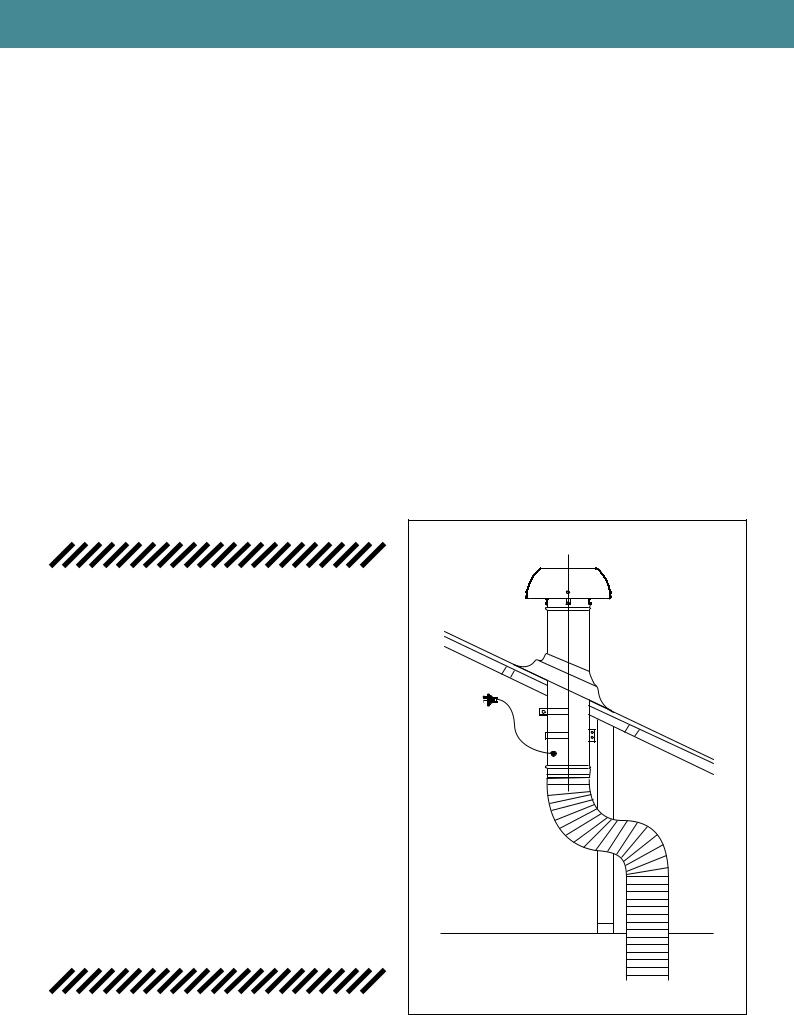
DUCTING & EXTRACTION LEVELS - (REMOTE MOTORS ONLY)
The Flexi ducting is designed to ensure optimum performance for your rangehood.
Please follow the installation instructions carefully.
Every FALMEC rangehood must be ducted to the external or in-roof motor unit by the use of non-flammable ducting. The rangehood must not be ducted into a wall cavity or a ceiling space where a build-up of grease can occur and become a potential fire risk. Ensure the external outlet on the motor unit unit is not covered and the air flow is not restricted in any way as this may result in reduced performance.
The duct must at all times have a cross sectional surface area equivalent to the hood outlet. The hood outlet has a circular cross section of 200 mm in diameter or an approximate area of 31,400 mm². Do not reduce the duct size at any time and avoid sharp bends. If the duct run is longer than five (5) metres, it may be necessary to enlarge the duct size to ensure optimum performance. The manufacturer does not guarantee performance when the duct length is greater than five (5) metres.
THE RECOMMENDED DUCT LENGTH (INSTALLATION DISTANCE) IS 4 METERS.
THE MINIMUM INSTALLATION DISTANCE IS 3 METERS.
GENTLE BENDS IN THE DUCTING ARE RECOMMENDED AS IT ASSISTS IN MUFFLING NOISE FROM THE
EXTERNAL FAN UNIT.
Gentle Bend |
In Ducting |
To Rangehood Unit |

SERVICING OF REMOTE MOTORS
The installation and fitting of the external or in-roof motor should be done in such a way that will allow the unit to be removed if service is required. Additional costs incurred in the removal, such as damage to walls and roofs, are not covered under warranty.
The external and in-roof motors unit should be checked regularly to ensure that nothing is obstructing the air flow from the housing. We also recommend a routine inspection of the remote units every 12 months to ensure optimum performance.
As part of ensuring the maximum life cycle of the remote motors it is advised to clean the baffle filters on the rangehood every 4 weeks. These filters are easily removable and dishwasher safe
PART 1: HOOD INSTALLATION GUIDE - INTEGRATED HOODS - ON BOARD MOTOR
ON BOARD HOOD
Models include SIENA F3SN60S1, F3SN90S1 and F3SND90S1
WARNING
DIMENSIONS ARE ACCURATE AT THE TIME OF PRINTING, PR KITCHEN & WASHROOM SYSTEMS PTY LTD RESERVES THE RIGHT TO CHANGE SPECIFICATIONS WITHOUT NOTICE. FOR BUILDING PURPOSES THE UNIT SHOULD BE PROVIDED TO THE CABINET MAKER / BUILDER / KITCHEN DESIGNER FOR EXACT MEASUREMENTS.
CONFIGURING HOOD FOR BACK DUCTED INSTALLATION
Note: Hood is delivered in with motor positioned for ducting through top of unit. To alter perform the following steps
STEP 1:
Remove external face plate covering back ducted hole by unscrewing at the two fixing points.
STEP 2:
Inside the hood locate the four fixing screws holding the motor and fixing plate to the top of the rangehood chasis. Remove the screws and rotate the motor 90° backwards and push motor flange through exposed hole in back of the chassis.
STEP 3:
Re-secure the motor and fixing plate to the back of the chassis with the 4 screws removed in step 2. Finally secure the external face plate removed in step 1 to the top of the rangehood and secure with at the two fixing points with the screws provided.
HOOD INSTALLATION
STEP 1:
To install into your overhead cupboard, several holes may need to be cut into shelves to enable the ducting to exit the cavity. Ensure the hood is mounted as close to the centre of the cooking surface as possible.
NOTE:
The height of the underside of the hood body must be a minimum of 600 mm above an electric cooktop & 650 mm above a gas cooktop and a maximum height of 1200 mm. If the instructions of the hob specify a greater distance than the minimum detailed, this shall be the minimum height for installation. Building codes that stipulate a minimum dimension may vary from state to state, please check with your local council prior to installation.
STEP 2:
If a shelf is fitted within the cupboard cut out a central 155mm hole in the shelf for ducting, matching the holes position to that of the outlet on top of the hood. Additional holes might need to be cut to feed the duct out to the roof cavity.
STEP 3:
Remove the screws from within the main body of the rangehood along the back above the grease trap, on the left and right side . Once the screws are removed, the main body of the rangehood will separate away from stainless steel fascia.

PART 1: HOOD INSTALLATION GUIDE - INTEGRATED HOODS - ON BOARD MOTOR
STEP 4:
The returns on the main body are now exposed. These are used to fix the main body on to the cabinetry. Place the hood in the cabinet in the level position ensuring that the controls and display will be visible when standing in front of the unit.
Using the pre-drilled mounting holes, screw the hood into position.
STEP 5:
Once the main body is secure into the cabinetry the stainless steel fascia can then be slid inside the main body.
The fascia will cover the screws that have fixed the main body into the cabinetry. Place the screws back into place which were removed in step 3.
STEP 6:
Connect the hood outlet (in the top or back ducted position) to 150 mm ducting leading to an external output.
STEP 7:
Attach the male plug of the rangehood unit to the main power supply.
Note to electricians: Standard 10 amp general power outlet (GPO) required.
Position GPO as close to the hood unit as possible.
GREASE TRAP AND BAFFLE FILTERS:
The integrated range of hoods utilize a removable grease trap that is used to catch excess amounts of grease and condensate from the baffle filters. This trap can be removed for cleaning. The trap consists of a concave channel with fixing points in the channel of the trap. The baffle filters will then sit within the channel, with the filter vanes running downward.
 Loading...