


Falmec Dora 120, Ginevra Tile 90, Iris Malizia 120, Iris Tulip 120, Iris Tulip 90 User Manual
...Cod. 110030251 (CAPPE CLASSICHE)
LIBRETTO ISTRUZIONI
INSTRUCTIONS BOOKLET
BEDIENUNGSSANLEITUNG
LIVRET D’INSTRUCTIONS
MANUAL DE INSTRUCCIONES
азлнкмдсаь ий щдлигмДнДсаа
INSTRUKCJE OBSŁUGI
Ed. 2011
Gentile Signora/Signore, congratulazioni!
Lei ha acquistato una cappa di prestigio e di sicura qualità. Perché Lei possa ottenere le migliori prestazioni, Le suggeriamo di seguire con attenzione le istruzioni per l’uso e manutenzione che troverà in questo libretto; inoltre, per ordinare i filtri di ricambio al carbone attivo utilizzi l’apposito tagliando che troverà allegato alla copertina.
Dear Sir/Madam, congratulations!
You have purchased a prestigious range hood of guaranteed quality. For best results, we suggest that you carefully follow the operating and maintenance instructions provided in this booklet; in addition, to order spare charcoal filters, use the special coupon on the cover.
Verehrte Kundin, verehrter Kunde
Kompliment! Sie haben eine qualitativ hochwertige Dunstabzugshaube erworben. Um ihre Leistungsfähigkeit optimal nutzen zu können, sollten Sie die beiliegende Gebrauchsund Wartungsanleitung sorgfältig durchlesen und befolgen. Für die Bestellung der ErsatzAktivkohlefilter verwenden Sie bitte den Coupon, der dem Deckblatt beiliegt.
Chère Madame/Cher Monsieur, félicitations!
Vous venez d’acheter une hotte haut de gamme. Pour en tirer les performances les meilleures veuillez lire avec attention le mode d’emploi et la maintenance que vous trouvez dans ce manuel ; pour commander les filtres de rechange au carbone actif veuillez vous servir du coupon annexé à la couverture.
Enhorabuena Señora/Señor!
Ha comprado una campana extractora de prestigio y calidad segura. Para que pueda obtener las mejores prestaciones, le sugerimos seguir con atención las instrucciones contenidas en este manual para el uso y el mantenimiento. Para pedir los filtros de recambio de carbón activo, utilice el cupón adjunto a la cubierta.
З˚ Ф ЛУ· ОЛ Ф ТЪЛКМУ Л ‚˚ТУНУН‡˜ТЪ‚ММУ ‚˚ЪflКМУ ЫТЪ УИТЪ‚У. СОfl ЪУ„У, ˜ЪУ·˚ УМУ ‰‡‚‡ОУ М‡ЛОЫ˜¯Л БЫО¸Ъ‡Ъ˚, НУПМ‰ЫП ‚МЛП‡ЪО¸МУ ТО‰У‚‡Ъ¸ ЛМТЪ ЫНˆЛflП ФУ ˝НТФОЫ‡Ъ‡ˆЛЛ Л ЫıУ‰Ы, НУЪУ ˚ ‚˚ М‡И‰Ъ ‚ ˝ЪУП ЛБ‰‡МЛЛ; Н УП ЪУ„У, ‰Оfl Б‡Н‡Б‡ Б‡Ф‡ТМ˚ı ЩЛО¸Ъ У‚ М‡ ‡НЪЛ‚Л У‚‡ММУП Ы„О ЛТФУО¸БЫИЪ
ÒԈˇθÌ˚È Ú‡ÎÓÌ, ÍÓÚÓ ˚È ‚˚ ÏÓÊÚ Ì‡ÈÚË Ô ËÍ ÔÎÌÌ˚Ï Í Ó·ÎÓÊÍ.
Szanowni Państwo Gratulujemy!
Zakupiliście prestiżowy okap kuchenny o gwarantowanej jakości. Dla uzyskania najlepszych wyników zalecamy, by starannie przestrzegać instrukcji obsługi i konserwacji zawartych w tej broszurze. Ponadto, do zamawiania zapasowych filtrów z węglem drzewnym, wykorzystywać specjalny kupon załączony na okładce.

650 mm (25,6”)
Fig. 1
650 mm (25,6”)
Fig. 2
Fig. C1
1
. 3
4
2
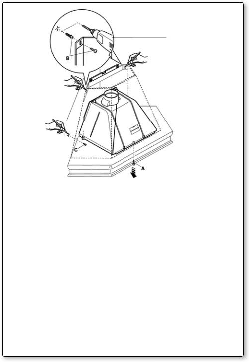
Fig. 5
Fig. 6
3
A FASTENING HOLES |
|
B HOB |
|
|
|
Fig. 7
STIRRUP A
TOP SECTION
CENTER SECTION
HOOD UNIT
Fig. 8
4

I LIBRETTO ISTRUZIONI
A 
 AVVERTENZE
Èmolto importante che questo libretto istruzioni sia conservato insieme al- l’apparecchiatura per qualsiasi futura consultazione.
Se l’apparecchio dovesse essere venduto o trasferito ad un’altra persona, assicurarsi che il libretto venga fornito assieme, in modo che il nuovo utente possa essere messo al corrente del funzionamento della cappa e delle avvertenze relative.
Queste avvertenze sono state redatte per la vostra sicurezza e per quella degli altri, Vi preghiamo, dunque, di volerlo leggere attentamente prima d’installare e di utilizzare l’apparecchio.
Questo apparecchio non deve essere utilizzato da bambini o persone infermi a meno che non siano adeguatamente controllate da persone responsabili che si assicurino che l’apparecchio sia utilizzato in sicurezza.
I bambini devono essere controllati da persona responsabile per assicurarsi che non giochino con l’apparecchio.
Il lavoro di installazione deve essere eseguito, da installatori competenti e qualificati, secondo le norme in vigore.
Se il cavo di alimentazione è danneggiato, esso deve essere sostituito dal costruttore o dal suo servizio assistenza tecnica o comunque da una persona con qualifica similare, in modo da prevenire ogni rischio.
Ogni eventuale modifica che si rendesse necessaria all’impianto elettrico per installare la cappa dovrà essere eseguita solo da persone competenti.
Èpericoloso modificare o tentare di modificare le caratteristiche di questo impianto. In caso di riparazioni o mal funzionamento dell’apparecchio, non tentare di risolvere da soli il problema.
Le riparazioni effettuate da persone non competenti possono provocare danni. Per eventuali interventi rivolgersi ad un Centro Assistenza Tecnica autorizzato ad eseguire parti di ricambio.
Controllare sempre che tutte le parti elettriche, (luci, aspiratore), siano spente quando l’apparecchio non viene usato. Leggere tutto il libretto istruzioni prima di effettuare operazioni sulla cappa.
L’utilizzo della cappa non può essere diverso da quello di aspiratori di fumi di cottura su cucine domestiche.
Qualsiasi utilizzo diverso da questo solleva il costruttore da qualsiasi responsabilità.
Il peso massimo complessivo di eventuali oggetti posizionatio appesi (ove previsto) sulla cappa non deve superare 1,5 Kg.
Dopo l’installazione delle cappe in acciaio inox bisogna eseguire la pulizia della stessa per rimuovere i residui di collante protettivo e le eventuali macchie di grasso o oli.
Per questa operazione il costruttore raccomanda l’utilizzo delle salviette in dotazione, disponibili anche in acquisto.
L’utilizzo di altre tipologie di detergenti solleva il costruttore dalla responsabilità sui danni che ne potrebbero derivare.
5
B |
CARATTERISTICHE TECNICHE
I dati tecnici dell’elettrodomestico sono riportati su delle targhette, posizionate all’interno della cappa.
C |
INSTALLAZIONE
(parte riservata solo a persone qualificate per il montaggio della cappa)
La distanza fra il piano cottura e la parte più bassa della cappa da cucina è di norma almeno 65 cm (vedi figura C1). Tale distanza è misurata a rigore nel punto più basso della cappa con tensione non di sicurezza. Sulla base di questa dettaglio previsto dalle norme Europee è possibile ridurre la distanza su alcuni modelli come specificato nel catalogo generale. Se le istruzioni del piano di cottura a gas specificano una distanza maggiore, bisogna tenerne conto.
Nella versione aspirante il tubo di uscita dei fumi deve avere un diametro non inferire a quello del raccordo della cappa.
Nei tratti orizzontali il tubo deve avere una leggera inclinazione (10% circa) verso l’alto per convogliare l’aria all’esterno dell’ambiente.
Ridurre al minimo le curve, verificare che i tubi abbiano una lunghezza minima indispensabile.
Rispettare le norme vigenti sullo scarico dell’aria all’esterno.
In caso di utilizzo contemporaneo di altre utenze (caldaie, stufe, caminetti, ecc.) alimentate a gas o con altri combustibili, provvedere ad una adeguata ventilazione del locale in cui avviene l’aspirazione dei fumi, secondo le norme vigenti.
Istruzioni di montaggio: vedi sez. “O” del presente manuale.
D |
ALLACCIAMENTO ELETTRICO
(parte riservata solo a persone qualificate per l’allacciamento)
ATTENZIONE!
Prima di effettuare qualsiasi operazione all’interno della cappa scollegare l’apparecchio dalla rete elettrica.
Assicurarsi che non vengano scollegati o tagliati fili elettrici all’interno della cappa; nel caso si verifichino tali situazioni contattare il centro assistenza più
vicino. Per l’allacciamento elettrico rivolgersi a personale qualificato.
Il collegamento deve essere eseguito in conformità con le disposizioni di legge in vigore. Controllare che la valvola limitatrice e l’impianto elettrico possano sopportare il carico dell’apparecchio (vedere targhetta caratteristiche tecniche al punto B). Alcuni tipi di apparecchi possono essere dotati di cavo senza spina; in questo caso, la spina da utilizzare deve essere dei tipo “normalizzato” tenendo conto che:
-il filo giallo-verde deve essere utilizzato per la messa a terra,
-il filo blu deve essere utilizzato per il neutro,
-il filo marrone deve essere utilizzato per la fase, il cavo non deve entrare in contatto con parti calde aventi temperature superiori a 70 °C.
-montare sul cavo di alimentazione una spina adatta al carico e collegarla ad
6
E |
una adeguata spina di sicurezza.
Se un apparecchio fisso non è provvisto di cavo di alimentazione e di spina, o di altro dispositivo che assicuri la disconnessione dalla rete, con una distanza di apertura dei contatti che consenta la disconnessione completa nelle condizioni della categoria di sovratensione III, le istruzioni devono indicare che tali dispositivi di disconnessione devono essere previsti nella rete di alimentazione conformemente alle regole di installazione.
Il cavo di terra giallo/verde non deve essere interrotto dall’interruttore. Prima di collegare l’apparecchio alla rete elettrica, controllare che:
-la tensione d’alimentazione corrisponda a quella indicata dalla targhetta caratteristiche tecniche.
-la presa di terra sia corretta e funzionale.
-l’impianto di alimentazione sia munito di efficace collegamento di terra secondo le norme vigenti.
-la presa o l’interruttore omnipolare usati siano facilmente raggiungibili con l’apparecchiatura installata.
La casa costruttrice declina ogni responsabilità nel caso le norme di sicurezza non vengano rispettate.
CAPPA IN VERSIONE
AD EVACUAZIONE ESTERNA (aspirante)
In questa versione i fumi e i vapori della cucina vengono convogliati verso l’esterno attraverso un tubo di scarico.
Il convogliatore di scarico che sporge sulla parte superiore della cappa deve essere collegato con un tubo che conduce i fumi e i vapori in una uscita esterna.
In questa versione vanno tolti i filtri al carbone attivo se esistenti; per l’estrazione vedere istruzioni al punto F. Quando la cappa da cucina viene utilizzata contemporaneamente ad altri apparecchi che impiegano gas o altri combustibili, il locale deve disporre di sufficiente ventilazione secondo le norme vigenti.
Deviazione per la Germania:
Quando la cappa da cucina e apparecchi alimentati con energia diversa da quella elettrica sono in funzione simultaneamente, la pressione negativa nel locale non deve superare i 4 Pa (4 x 10⁻⁵ bar).
F |
CAPPA IN VERSIONE
A RICICLO INTERNO (filtrante)
In questa versione l’aria passa attraverso i filtri di carbone attivo per essere purificata e viene riciclata nell’ambiente cucina.
Controllare che i filtri al carbone attivo siano montati sul motore, in caso negativo applicarli come indicato nelle istruzioni al punto H.
Se la cappa viene predisposta in versione filtrante rimuovere la valvola di non ritorno montata sul raccordo di uscita del motore.
7
G |
Per il miglior rendimento si consiglia di utilizzare la terza velocità in presenza di forti odori e vapori, la seconda velocità nelle condizioni normali, la prima velocità per mantenere l’aria pulita con bassi consumi di energia elettrica.
Si consiglia di mettere in funzione la cappa quando si inizia a cuocere e manteneria in funzione fino alla scomparsa degli odori.
FUNZIONAMENTO
1. COMANDO A 2 TASTI
LUCE - Interruttore A
Posizione 0: la luce sarà sempre spenta.
Posizione 1: la luce sarà sempre accesa.
VELOCITÀ - Interruttore B
Permette l’accensione e la regolazione delle velocità di esercizio dei motore, a seconda delle versioni da 1 a 3, o tramite un variatore continuo di velocità.
SPIA - C
Gemma spia di funzionamento dei motore.
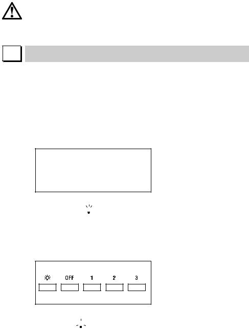
2. PULSANTIERA A 5 TASTI
LUCE - Pulsante 

ON/OFF LUCE
MOTORE - Pulsante 1, 2, 3, OFF
1:avvia il motore alla velocità minima
2:avvia il motore alla velocità media
3:avvia il motore alla velocità massima OFF: spegne il motore
3.PULSANTIERA ELETTRONICA
Pulsante luce 

•ON: luce accesa (pulsante illuminato);
•OFF: luce spenta;
Pulsante -
Premendo il tasto si riduce la velocità del motore.
8
La velocità 1, 2 e 3 è visualizzata dal n° di led accesi escluso led luce e timer.
Pulsante +
Premendo il tasto si incrementa la velocità del motore.
La velocità 1,2 e 3 è visualizzata dal n° di led accesi escluso led luce e timer.
(Nella versione a 4 velocità il tasto + presenta una luce intermittente. La 4° velocità o intensiva è temporizzata e dopo circa 15 minuti il motore passa automaticamente in 3° velocità).
Pulsante modalità
Funzione: accensione e spegnimento motore cappa.
La funzione velocità desiderata permette di avviare il motore con l’ultima velocità selezionata prima del precedente spegnimento.
Optional: versione con radiocomando (disponibile solo su alcune versioni).
AVVERTENZE (versione con radiocomando):
Posizionare l’apparecchio lontano da sorgenti di onde elettromagnetiche che potrebbero interferire con l’elettronica della cappa
Distanza massima di funzionamento 5 metri. Tale distanza può variare in difetto in funzione delle interferenze elettromagnetiche di altri apparecchi. Pulsante luce del telecomando: on/off luce.
Pulsante – e + decremento/incremento velocità (per avviare il motore premere indifferentemente tasto + o in tasto -.
Pulsante timer: vedi istruzione sottostante.
Pulsante timer e saturazione filtri 
•Questa funzione permette lo spegnimento automatico della cappa dopo 15 minuti di funzionamento alla velocità precedentemente impostata (pulsante con luce intermittente).
•Dopo circa 30 ore di funzionamento il pulsante propone il lavaggio dei filtri metallici (pulsante illuminato di rosso). Per disattivare l’allarme premere il pulsante timer per qualche secondo fino allo spegnimento della luce rossa. Successivamente spegnere la cappa e riaccenderla per verificare l’annullamento dell’allarme.
H |
FILTRI ISTRUZIONI PER L’ESTRAZIONE E LA SOSTITUZIONE
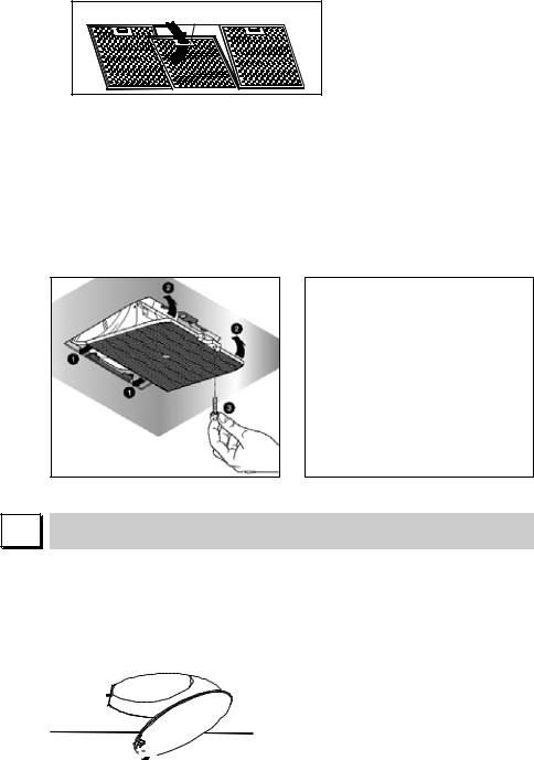
1. FILTRI METALLICI
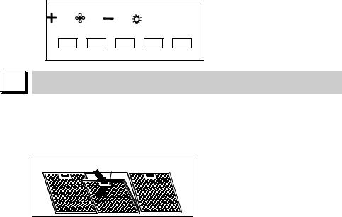
Per l’estrazione dei filtro metallico antigrasso è sufficiente agire sulla maniglia A fino a quando esce dalla guida anteriore; a questo punto, inclinando leggermente verso il basso, farlo uscire dalla guida posteriore. Per l’inserimento invertire l’operazione.
9
A |
2. FILTRI AL CARBONE ATTIVO
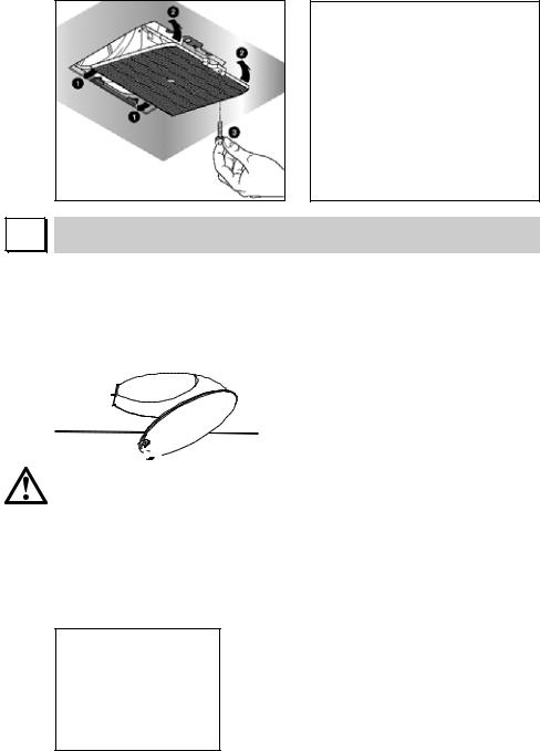
Per la sostituzione dei filtri al carbone attivo si proceda come segue: togliere i filtri metallici come indicato sopra. A questo punto si accede facilmente ai due filtri che sono agganciati sul lato dx e sx del convogliatore.
Per il montaggio/sostituzione vedi figura.
Nel caso di cappa con camera motore il filtro è posizionato nella parte inferiore della camera stessa. Per il montaggio/sostituzione vedi figura. Per ordinare i nuovi filtri carbone rivolgersi al distributore/rivenditore.
SOLO PER ITALIA: Scaricare l’apposito modulo ordine filtro sul sito: www. falmec.com (accedere sul menù a tendina assistenza).
I |
ILLUMINAZIONE MONTAGGIO E SOSTITUZIONE
1. LAMPADA A PLAFONIERA
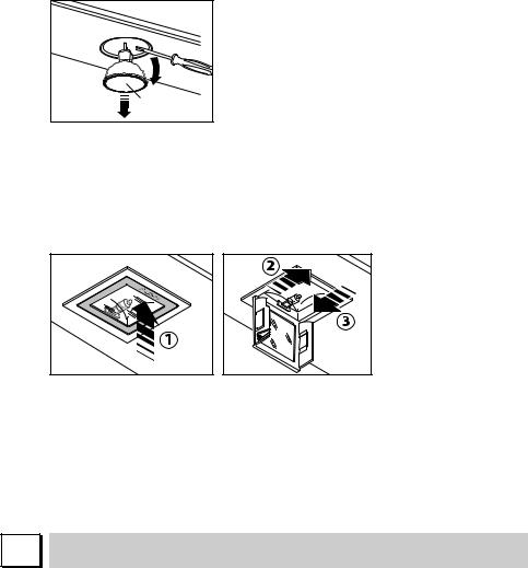
Per sostituire la lampada:
a)Accertarsi che l’apparecchio sia scollegato dalla rete elettrica.
b)Svitare la vite di sostegno A e rimuovere la plafoniera (vedi figura).
c)Sostituire la lampada con una dello stesso modello di quella originale (max 25 W, vedi indicazione posta in prossimità della lampada).
A


10
ATTENZIONE! Lampade di forma e portata diverse da quella originale potrebbero danneggiare seriamente il vano illuminazione.
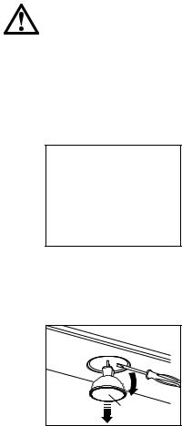
2. FARETTO
Per sostituire la lampada del “Round halogen light”:
a)Accertarsi che l’apparecchio sia scollegato dalla rete elettrica.
b)Togliere, facendo leva con un cacciavite, l’anello di supporto del vetro A.
c)Togliere il vetro B per accedere al vano lampada.
d)Sostituire la lampada con una analoga (alogena max 20 W, 12 Volt attacco G4).
e)Rimontare il vetro di protezione B fissandolo con l’apposito anello A.
Round halogen light
Per sostituire la lampada “Dicroic lamp”:
a)Accertarsi che l’apparecchio sia scollegato dalla rete elettrica.
b)Rimuovere la lampada utilizzando un cacciavite (vedi figura)
c)Sostituire la lampada con una analoga (dicroica max 20 W, 12 Volt).
Lamp |
Dicroic spot
Per sostituire la lampada del “Square halogen light”:
a)Accertarsi che l’apparecchio sia scollegato dalla rete elettrica.
b)Aprire completamente il pannello fino ad un angolo di 90° (vedi figura) premendo su PUSH
c)Sostituire la lampada con una analoga (alogena max 20 W, 12 Volt attacco G4).
d)Richiudere i pannello. Se il pannello non si richiude correttamente ripetere l’operazione al punto b.
11
Square halogen light
3. LAMPADA FLUORESCENTE
(parte riservata solo a personale qualificato)
Sostituzione del tubo fluorescente:
a)Scollegare l’apparecchio dalla rete di alimentazione;
b)Rimuovere l’eventuale pannello in acciaio svitando le viti di fissaggio;
c)Togliere il tubo fluorescente ruotandolo di 90° e sostituirlo con uno di analoghe caratteristiche (8W-13W-21W-28W a seconda del modello);
d)Ricollegare l’apparecchio alla rete di alimentazione.
L |
MANUTENZIONE E PULIZIA
Una costante manutenzione garantisce un buon funzionamento ed un buon rendimento nel tempo. Particolari attenzioni vanno rivolte ai filtri metallici antigrasso ed ai filtri al carbone attivo, infatti la pulizia frequente dei filtri e dei loro supporti garantisce che sulla cappa non si accumulino grassi che sono pericolosi per la facilità di incendio.
1. FILTRI ANTIGRASSO METALLICI
Hanno la funzione di trattenere le particelle grasse in sospensione, pertanto si consiglia di lavarli ogni mese in acqua calda e detersivo evitando di piegarli. Attendere che siano ben asciutti prima di rimontarli.
Per lo smontaggio e montaggio vedi istruzioni al punto H1. Si raccomanda costante frequenza nell’operazione.
2. FILTRI AL CARBONE ATTIVO
Hanno la funzione di trattenere gli odori presenti nel flusso d’aria che li attraversa. L’aria depurata per successivi passaggi attraverso i filtri viene rimessa nell’ambiente cucina. l filtri al carbone attivo non possono essere lavati e vanno sostituiti mediamente ogni 3-4 mesi (dipende poi dall’uso). Per la sostituzione dei filtri al carbone attivo seguire le istruzioni come al punto H2.
3. PULIZIA ESTERNA
Si raccomanda di pulire le superfici esterne delle cappe almeno ogni 15 giorni per evitare che le sostanze oleose o grasse possano intaccare le superfici in acciaio.
La pulizia della cappa va eseguita usando un panno umido con detersivo liquido neutro o con alcool denaturato.
Nel caso di materiale con trattamento antimpronta (Fasteel) eseguire la pulizia solo con acqua e sapone neutro utilizzando un panno morbido
12
M |
avendo cura di risciacquare e asciugare accuratamente. Non si devono utilizzare prodotti contenenti sostanza abrasive, panni con superfici ruvide o panni comunemente in commercio per la pulizia dell’acciaio. L’utilizzo di sostanze abrasive e panni ruvidi danneggerà irreparabilmente il trattamento superficiale dell’acciaio.
Conseguenza diretta del non rispetto di tali avvertenze sarà il deterioramento irreversibile della superficie dell’acciaio.
Tali avvertenze dovranno essere conservate insieme al libretto istruzioni della cappa.
Il produttore declina ogni responsabilità qualora non vengano rispettate tali istruzioni.
4.PULIZIA INTERNA
É vietata la pulizia di parti elettriche o parti relative al motore all’interno della cappa, con liquidi o solventi;
Non usare prodotti contenenti abrasivi.
Effettuare tutte queste operazioni scollegando preventivamente l’apparecchio dalla rete elettrica.
SICUREZZA AVVERTENZE
L’impianto elettrico è munito di collegamento a terra secondo le norme di sicurezza internazionali; è inoltre conforme alle normative Europee sull’antidisturbo radio.
Non collegare l’apparecchio a condotti di scarico dei fumi prodotti dalla combustione (caldaie, caminetti,ecc). Verificare che la tensione di rete corrisponda a quella riportata dalla targhetta posta all’interno della cappa.
La distanza minima di sicurezza tra il piano di cottura e la cappa deve essere di almeno 65 cm.
Non fare cotture a fiamma “libera” sotto la cappa. Controllare le friggitrici durante l’uso: I’olio surriscaldato potrebbe infiammarsi.
-Assicurarsi che vi sia una adeguata ventilazione nella stanza se la cappa è utilizzata con altri apparecchi che utilizzano combustibili come gas o altro.
-Non accendere fiamme libere sotto la cappa.
-Non collegare l’apparecchio a condotti di scarico dei fumi prodotti dalla combustione (caldaie, caminetti, ecc).
-Assicurarsi che tutte le normative vigenti sullo scarico dell’aria all’esterno del locale siano rispettate prima dell’utilizzo della cappa.
Prima di procedere a qualsiasi operazione di pulizia o di manutenzione, disinserire l’apparecchio togliendo la spina o agendo sull’interruttore generale. La casa costruttrice declina ogni responsabilità per eventuali danni che possano, direttamente o indirettamente, essere causati a persone, cose ed animali domestici in conseguenza alla mancanza di tutte le prescrizioni indicate nell’apposito libretto istruzioni e concernenti, specialmente, le avvertenze in tema di installazione, uso e manutenzione dell’apparecchio.
13
N |
GARANZIA
La sua nuova apparecchiatura è coperta da garanzia.
Le condizioni di garanzia sono riportate per esteso sull’ultima pagina di copertina di questo libretto.
La casa costruttrice non risponde delle possibili inesattezze, imputabili ad errori di stampa o di trascrizione, contenute nel presente libretto. Si riserva di apportare ai propri prodotti quelle modifiche che ritenesse necessarie o utili, anche nell’interesse dell’utenza, senza pregiudicare le caratteristiche essenziali di funzionalità e di sicurezza.
O |
ISTRUZIONI MONTAGGIO CAPPA PARETE RUSTICA
Fase 1
-Appoggiare alla parete la barra di sostegno (A-Fig. 1), ad un’altezza dal piano cottura determinata dalla somma delle quote X+Y+265mm.
-Controllare con una bolla di livello l’allineamento orizzontale e segnare alle estremità della barra n° 2 punti di foratura.
-Forare, inserire n° 2 tasselli ad espansione ø 8mm e fissare la barra con le relative viti.
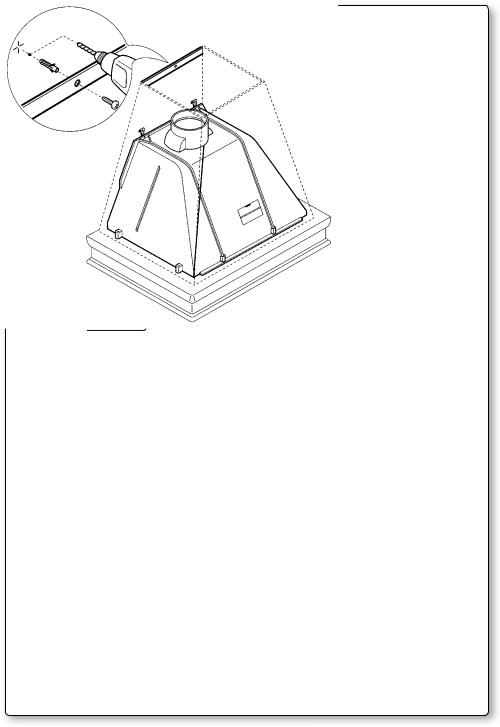
Fase 2
- Agganciare la cappa alla barra di sostegno (Fig. 2).
Fase 3
-Regolare l’allineamento della cappa tramite le viti delle attaccaglie (Fig. 3). La vite superiore (B) regola la distanza dalla parete, quella inferiore (C) lo scorrimento verticale.
Fase 4
-Per evitare lo sganciamento della cappa dovuto ad una pressione sottostante, fissarla alla parete con un tassello ad espansione e relativa vite attraverso l’apposito foro (Fig. 4).
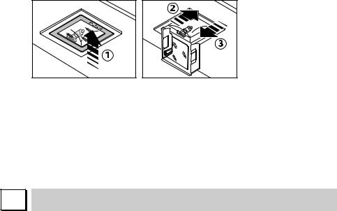
ISTRUZIONI MONTAGGIO CAPPA AD ANGOLO SENZA BARRA
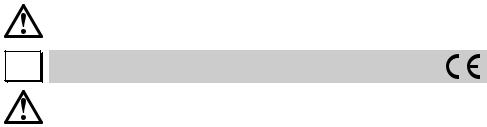
Fase 1
-Svitare la vite metrica posteriore (A) e sganciare il gruppo motore dal fondo cappa (fig. 1).
-Controllare con una bolla di livello l’allineamento orizzontale e segnare n° 4 punti di foratura.
-Forare, inserire n° 2 tasselli ad espansione ø 8mm e fissare la cappa nella posizione desiderata tramite 2 viti B fissati nelle due asole poste sulla schiena superiore (Fig. 5).
-Fissare le due viti di sicurezza C posizionate sulla schiena inferiore.
14

Fase 2
-Dopo aver fissato la cappa, collegare il tubo flessibile al foro di scarico fumi e al raccordo circolare della camera motore.
-Riagganciare il gruppo motore sul fondo della cappa e fissarlo tramite la vite metrica posteriore (A) (fig. 2).
FISSAGGIO CAPPA SENZA CAMERA MOTORE
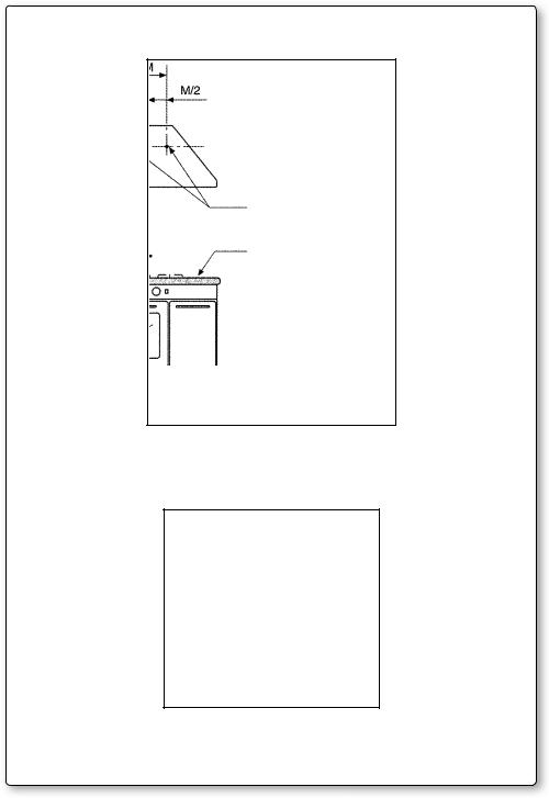
1)Rilevare la distanza (L) dal fondo della cappa al centro dei fori di fissaggio (fig. 7).
2)Rilevare la distanza (M) tra i due fori di fissaggio.
3)Far coincidere la linea di mezzeria del piano cottura con quella della cappa in modo tale da suddividere a metà “M” (“M/2”).
4)La posizione in altezza dei fori da eseguire, rispetto al piano di cottura è di L+650 mm.
5)Eseguire i fori con il trapano per il posizionamento dei fischer (il diametro dei fori è determinato dal tipo di fischer).
6)Prima di appendere la cappa, per poter in seguito assicurarsi che sia ben fissata, togliere:
-le griglie in acciaio se la cappa è con motore tangenziale
-tutto il gruppo ad incasso, svitando le viti che lo sorreggono al fondo, se la cappa è dotata appunto di gruppo ad incasso.
7)Per evitare lo sganciamento della cappa dovuto ad una pressione sottostante, fissarla alla parete con un tassello ad espansione e relativa vite utilizzando gli appositi fori presenti sul retro della cappa o le staffe del coperchio.
8)Appende la cappa.
9)Verificare, attraverso il buco sul fondo, che la cappa sia ben ancorata ai ganci dei fischer.
10)Regolare l’altezza della cappa tramite le viti poste sui ganci dei Fischer.
11)Montare le griglie in acciaio o il gruppo ad incasso.
12)Fissaggio kit camino (fig. 8):
-Fissare al muro, alla distanza opportuna, la staffa (A), usando le viti in dotazione;
-fissare la prolunga alla staffa (A) usando le viti in dotazione.
15
GB INSTRUCTIONS BOOKLET
A 
 WARNINGS
This instruction booklet must be kept together with the appliance for future reference. If the appliance is sold or consigned to other parties, check that the booklet is supplied with it, to ensure that the new user has the correct information on the operation of the range hood and is aware of the warnings. These warnings have been provided for the your safety and the safety of others. As a result, please read them carefully before installing and operating the appliance.
This appliance is not intended for use by young children or infirm persons unless they have been adequately supervised by a responsible person to ensure that they can use the appliance safely. Young children should be supervised to ensure they do not play with the appliance.
The appliance must be installed by qualified personnel, in accordance with the standards in force. If the supply cord is damaged, it must be re-placed by the manufacturer, its service agent or similarly qualified persons in order to avoid a hazard. Any modifications that may be required to the electrical system for the installation of the range hood must only be made by qualified electricians.
It is dangerous to modify or attempt to modify the characteristics of this system. In the event of malfunctions or if repairs are required to the appliance, do not attempt to solve the problems directly.
Repairs performed by unqualified persons may cause damage. For all repair and other work on the appliance, contact an authorised service/spare parts centre.
Always check that all the electrical parts (lights, exhaust device), are off when the appliance is not being used. Read the entire instruction booklet before performing any operations on the range hood.
The range hood must only be used for the exhaust of cooking fumes in home kitchens. The manufacturer disclaims all liability for any other use of the appliance.
The maximum weight of any object placed above the hood, or hung to it (if possible) must not exceed 1,5 kilos. After installing the stainless steel hood, clean it in order to remove any residue of the protective glue, and stains of grease or oil. The manufacturer recommends its cleaning cloth available for purchase. The manufacturer accepts no liability in case of damage caused by the use of different detergent types.
B |
TECHNICAL SPECIFICATIONS
The technical data pertaining to the electric appliance The technical specifications of the appliance are shown on the rating plates located inside the range hood.
16
C |
INSTALLATION
(Section reserved for qualified installers of the range hood)
The distance between the hob and the lowest part of the rangehood is normally at least 65 cm (see figure C1). This distance is measuresd in the lowest part of the rangehood not operating at safety voltage. Based on this detail provided by European Standards, the distance may be reduced in some models as specified in the general catalogue. If the instructions for installation for the gas hob specify a greater distance, this has to be taken into account.
In the outside exhaust version, the diameter of the fume discharge duct must be no smaller than the range hood connection.
In the horizontal sections, the duct must slope slightly (around 10%) upwards, so as to better convey the air outside of the room.
Avoid using angled pipes, make sure that the pipes are at least of the minimum length.
Comply with the current regulations on air discharge into the atmosphere.
If a boiler, stove, fireplace, etc. that uses gas or other fuels is being used at the same time, make sure the room where the fumes are extracted is well ventilated, in compliance with the current regulations.
Mounting instruction: see section “O” of the booklet.
D |
ELECTRICAL CONNECTIONS
(Section reserved for qualified installers)
WARNING!
Before doing any work inside the range hood, disconnect the appliance from the mains power supply.
Check that the wires inside the range hood are not disconnected or cut; if this is the case, contact your nearest service centre. The electrical connections must be performed by qualified personnel.
The connections must be performed in compliance with the legal standards in force. Check that the relief valve and the electrical system are able to support the load of the appliance (see the technical specifications in point B).
Some types of appliance are supplied with a cable without plug; in this case, “standardised” plugs must be used, keeping in mind that:
-the yellow-green wire must be used for the earth,
-the blue wire must be used for the neutral,
-the brown wire must be used for the phase; the cable must not come into contact with hot parts (over 70°C).
-fit a plug that is suitable for the load to the power cable, and connect it to a suitable power outlet.
For appliances that come supplied with cable and plug please ensure they are plugged into a circuit suitable for this appliance.
Please refer to a qualifed person. (See technical specifications in point B).
The manufacturer declines all liability if the safety standards are not observed.
17
E |
RANGE HOOD WITH OUTSIDE
DISCHARGE (exhaust)
In this version, the fumes and steam from the kitchen are conveyed outside through an exhaust duct.
The exhaust conveyor that protrudes from the upper part of the range hood must be connected to a duct that carries the fumes and steam outside. In this version, the charcoal filters, if fitted, should be removed; to do this, see the instructions in point F. There must be adequate ventilation of the room when the range hood is used at the same time as appliances burning gas or other fuels, according to the standard.
Deviation for Germany:
When the range hood and appliances supplied with energy other than electricity are simultaneously in operation, the negative pressure in the room must not exceed 4 Pa (4x10 E-5 bar).
F |
RECIRCULATING RANGE HOOD (with filter)
G |
In this version, the air passes through charcoal filters for purification, and is then recirculated back into the kitchen.
Check that the charcoal filters are fitted to the motor, and if not, install them as described in the instructions in point H.
If the hood is of filtering type, remove the non-return valve fitted at the motor’s outlet.
For maximum efficiency, the third speed should be used when there are strong odours or a lot of steam, the second speed in normal conditions, and the first speed for keeping the air clean with minimum energy consumption. The range hood should be switched on when starting to cook, and left on until the odours disappear.
OPERATION
1. TWO BUTTON CONTROL PANEL
LIGHT - Switch A
Position 0: the light is off. Position 1: the light is on.
SPEED - Switch B
This is used to start and set the speed of the motor, from 1 to 3, or with continuous speed variator, depending on the version.
LIGHT - C
Motor operation indicator light.
18
2. FIVE BUTTON CONTROL PANEL
LIGHTbutton 

Pressed: the light is on
Released: the light is off
MOTOR button - 1, 2, 3, OFF
1:starts the motor at minimum speed
2:starts the motor at medium speed
3:starts the motor at maximum speed OFF: stops the motor
3.ELECTRONIC CONTROL PANEL
Light pushbutton 

•ON: light on (the pushbutton is lit);
•OFF: light off;
Pushbutton -
Press to reduce motor speed
Speed 1, 2 and 3 are indicated by the number of LEDs that light up (excluding the light and the timer LEDs).
Pushbutton +
Press to increase motor speed
Speed 1, 2 and 3 are indicated by the number of LEDs that light up (excluding the light and the timer LEDs).
(In the 4-speed version the pushbutton + blinks. The fourth speed remains on for a set duration of time. After 15 minutes the motor returns to the third speed).
Mode pushbutton
Function: it turns hood motor on and off.
The function “desired speed” enables to start the motor at the speed that was selected before the hood was last turned off.
Optional: version with remote control (some versions only).
WARNING:
Install the hood away from sources of electromagnetic waves, as these could affect the correct operation of the electronic system.
Maximum operating distance: 5 metres. The maximum operating distance could be less than 5 metres in case of electromagnetic interference by other equipment.
19
Light pushbutton on remote control: light on/off.
– and + pushbutton: increase/decrease speed (to start the motor press either the + or the – pushbutton).
Timer pushbutton: see instructions below.
Timer and ‘filter clogged’ alarm pushbutton 
•This function allows the automatic turning off of the hood after running for 15 minutes at the speed previously set (the pushbutton shows a flickering light).
•After about 30 hours of running the pushbutton indicates the need for washing the metal filters (the pushbutton shows a solid red light). To disable the alarm press the pushbutton for a few seconds until the red light turns off. Then turn the hood off and on again to check that the alarm has disappeared.
H |
FILTERS REMOVING AND REPLACING’S INSTRUCTIONS
1. METAL FILTERS
To remove the metal grease-trapping filter, simply pull the handle A until releasing it from the front guide; then tilt it slightly downwards, and slide it out of the rear guide. To reposition the filter, repeat the operation in the reverse order.
A |
2. CHARCOAL FILTERS
To replace the charcoal filters, proceed as follows: remove the metal filters as described above. The two filters located at the ends of the motor can now be easily accessed.
To install the new filters see picture.
In case of hood with the motor box the filter is located on the botton part of the motor box.
To install the new filters see picture.
To order new charcoal filters contact the distributor/retailer.
VALID ONLY FOR ITALY: download the appropriate order form from: www. falmec.com (access the assistance drop-down menu).
20
I |
LIGHTING ASSEMBLY AND REPLACEMENT
1. LIGHT BULB
To replace the light bulb:
a)Make sure the appliance is disconnected from the mains power supply.
b)Unscrew the support screw A and remove the light cover.
c)Replace the light bulb with the same model as the original (max 25 W, see the markings near the light).
A


WARNING! Light bulbs with different shapes and power ratings from the original may seriously damage the light compartment.
2. SPOTLIGHT
To replace the lamp for “Round halogen light”:
a)Make sure the appliance is disconnected from the mains power supply.
b)Remove, by levering with a screwdriver, the support ring A for the cover glass.
c)Remove the cover glass B to access the light compartment.
d)Replace the lamp with the same type (halogen, max 20 W, 12 Volt, G4 fitting).
e)Replace the glass cover B and fasten it using the special ring A.
Round halogen light
21
How to replace the dicroic lamp:
a)Check that the equipment is disconnected from the power supply.
b)Remove the lamp with the help of a screwdriver (see figure)
c)Replace the lamp with a similar one (dichroic, max 20 W, 12 Volt).
Lamp |
Dicroic spot
How to replace a square halogen light:
a)Check that the equipment is disconnected from the power supply.
b)Open the panel completely till 90° (see figure) pressing the PUSH button
c)Replace the lamp with a similar one (halogen, max 20 W, 12 Volt, G4 connection).
d)Close the panel. If the panel does not close correctly repeat the operation at point b.
L |
Square halogen light
3. FLUORESCENT TUBE
(Section reserved for qualified installers)
Replacing the fluorescent tube:
a)Disconnect the device from the mains;
b)Unscrew the fixing screws and remove the bottom panel;
c)Remove the fluorescent tube, by rotating through 90°, and replace it with one of similar features (8W-13W-21W-28W according with the model);
d)Reconnect the device to the mains.
MAINTENANCE AND CLEANING
Constant maintenance ensures the correct operation and efficiency of the appliance over time. Special attention should be paid to the metal grease-trapping filters and the charcoal filters. Frequent cleaning of the filters and their supports will ensure that fats and grease do not accumulate on the range hood, with the consequent risk of fire.
1. METAL GREASE-TRAPPING FILTERS
These trap the fat and grease particles suspended in the air, and therefore should be washed every month in hot water and detergent, without bending
22
M |
them. Wait until they are completely dry before repositioning them.
To remove and replace these filters, see the instructions in point H1. This operation should be performed at regular intervals.
2. CHARCOAL FILTERS
These trap the odours present in the stream of air that passes through them. The air is purified by passing a number of times through the filters and being recirculated into the kitchen. The charcoal filters cannot be cleaned, and should be replaced on average every 3-4 months (according to use). To replace the charcoal filters, see the instructions in point H2.
3. CLEANING THE OUTSIDE OF THE APPLIANCE
It is advised to clean the external hood surfaces at least every 15 days in order to avoid that oily or greasy substances affect the steel surfaces.
The ouside of the range hhod should be cleaned using a damp cloth and neutral liquid detergent or denatured alcohol.
In case of fingerprint-less finish (fasteel) clean only with water and neutral soap using clean with a soft cloth, rinse and wipe dry thoroughly. Do not use products that contain abrasive substances, rough cloths or cloths specifically designed for cleaning steel. Using abrasive substances or rough cloths will inevitably damage the finish of steel.
The steel surface will be irrevocably damaged if the instructions above are not complied with.
Keep these instructions together with the instructions for use of your hood. The manufacturer accepts no liability for any damage caused by non-compli- ance with the instructions above.
4. CLEANING THE INSIDE OF THE APPLIANCE
The electrical parts or parts of the motor assembly inside the range hood must not be cleaned using liquids or solvents.
Do not use abrasive products.
All the above operations must be performed after having disconnected the appliance from the mains power supply.
SAFETY WARNINGS
The electrical system features an earth connection in compliance with international safety standards; furthermore, it is compliant with the European standard for electromagnetic compatibility.
Do not connect the appliance to flues (from boilers, fireplaces, etc.). Make sure the mains voltage corresponds to the values on the rating plate located inside the range hood. The minimum safety distance between the cooktop and the range hood must be at least 65 cm.
Never cook on “open” flames under the range hood.
Check deep-fryers during use: superheated oil may be flammable.
-Ensure there is adequate ventilation of the room when the rangehood is used at the same time as appliances burning gas or other fuels.
-Do not flambe under the rangehood
-The exhaust air must not be discharged into a flue which is used for exhausting fumes from appliances burning gas or other fuels.
23
N |
-Ensure that all regulations concerning the discharge of exhaust air have been fulfilled before you use the appliance.
Before performing any cleaning or maintenance operations, disconnect the appliance by unplugging it or using the main switch. The manufacturer disclaims all liability for any damage that may be directly or indirectly caused to people, things and animals due to the failure to follow all the instructions provided in this booklet and above all the warnings relating to the installation, operation and maintenance of the appliance.
WARRANTY
The new equipment is covered by warranty. The warranty conditions are provided by the distributor.
The manufacturer is not liable for any inaccuracies in this booklet resulting from printing or transcription errors. The manufacturer reserves the right to modify its products as it considers necessary or in the interests of the user, without compromising their essential safety and operating characteristics.
O |
ASSEMBLY INSTRUCTIONS FOR WALL-MOUNTED RUSTIC HOOD
Step 1
-Rest the support batten (A-Fig. 1) against the wall at a height above the hob determined by the sum of the values X+Y+265 mm.
-Use a spirit level to make sure it is perfectly horizontal and make 2 marks at the ends of the batten where the 2 holes are to be drilled.
-Drill the holes, insert the two ø 8mm screw anchors and fasten the batten using the relevant screws.
Step 2
- Hook the hood onto the support batten (Fig. 2).
Step 3
-Adjust the alignment of the hood using the screws on the brackets (Fig. 3). The upper screw (B) is used to adjust the distance from the wall, and the lower screw (C) the vertical sliding
Step 4
-In order to prevent the hood from unhooking owing to pressure from underneath, fasten it to the wall with a screw anchor and relevant screw inserted in the appropriate hole (Fig. 4).
ASSEMBLY INSTRUCTIONS FOR CORNER HOODS WITHOUT BAR
Step 1
-Undo the rear metric screw (A) and remove the motor from the bottom of the hood (fig. 1).
-Check the horizontal alignment with a spirit level and mark the 4 holes to be drilled.
-Drill the holes, insert 2 x 8mm dia. screw anchors and fix the hood in the desired
24

position, using 2 screws B fixed in the two slots in the top back panel (Fig. 5). - Fit the safety screws C in the bottom back panels (Fig. 5).
Step 2
-After having fixed the hood, connect the flexible hose to the fume outlet hole and to the circular pipe fitting of the motor chamber.
-Replace the motor at the bottom of the hood and secure it with the rear
metric screw (A) (fig. 2).
MOUNTING THE RANGE HOOD WITHOUT MOTOR CHAMBER
1)Measure the distance (L) from the bottom of the range hood to the centre of the mounting holes (Fig. 7).
2)Measure the distance (M) between the two mounting holes.
3)Line up the centre of the cooktop with the centre of the range hood. Is: L+650 mm.
4)The height of the holes to be drilled above the cooktop is calculated by adding
(L) to (H), where (H) is defined by point C-1.
5)Drill the holes for the Fischer screw anchors (the diameter of the holes depends on the type of screw anchor).
6)Before hanging and securing the range hood, remove:
- the steel grilles for range hoods with tangential motors
- the entire build-in assembly, if fitted, by unscrewing the screws that secure it to the bottom.
7)To avoid hood unhooking due to underneath pressure, fix it to the wall with a screw anchor and related screw, by using the appropriate holes at the back of the hood or the cope flasks.
8)Hang the range hood.
9)Check, through the hole at the bottom, that the range hood is properly anchored to the Fischer hooks.
10)Adjust the height of the range hood using the screws on the Fischer hooks.
11)Fit the steel grilles or the build-in assembly.
12)Mounting instruction for chimney (fig. 8):
- Fasten bracket (A) to the wall, at the correct distance; - Fasten the upper part of the extension to bracket (A).
25
D BEDIENUNGSANLEITUNG
A 
 HINWEISE
Diese Bedienungsanleitung muss unbedingt zusammen mit dem Gerät aufbewahrt werden, um in Zukunft nachgeschlagen werden zu können.
Sollte das Gerät verkauft bzw. einer anderen Person übergeben werden, muss die Bedienungsanleitung unbedingt mitgeliefert werden, damit der neue Benutzer mit dem Betrieb der Dunstabzugshaube und den diesbezüglichen Hinweisen vertraut werden kann.
Diese Hinweise sind für Ihre Sicherheit und die anderer Personen abgefasst worden. Daher sollten Sie die Bedienungsanleitung vor der Installation und Verwendung des Gerätes aufmerksam durchlesen.
Das Gerät darf nicht von Kindern bzw. Behinderten benutzt werden, es sei denn diese werden von verantwortungsvollen Personen, die dafür Sorge tragen, dass das Gerät sicher verwendet wird, überwacht.
Kinder müssen von einer von verantwortungsvollen Person überwacht werden, damit sie nicht mit dem Gerät spielen.
Die Installation hat den geltenden Vorschriften gemäß von kompetenten, qualifizierten Installateuren durchgeführt zu werden.
Beschädigte Speisekabel sind vom Hersteller bzw. von dessen Kundenservice bzw. von einer Person mit ähnlicher Qualifikation auszuwechseln, um Gefahren vorzubeugen.
Eventuelle erforderliche Änderungen, die für die Installation der Dunstabzugshaube an der elektrischen Anlage durchgeführt werden müssen, dürfen ausschließlich von kompetenten Personen vorgenommen werden.
Es ist gefährlich, die Eigenschaften dieser Anlage abzuändern bzw. versuchen abzuändern. Bei Reparaturen bzw. Betriebsstörungen des Gerätes nicht versuchen, das Problem alleine zu lösen.
Die Reparaturen, die von nicht kompetenten Personen durchgeführt werden, können Schäden verursachen.
Sich für eventuelle Eingriffe an einen zugelassenen Kundenservice, der über die geeigneten Ersatzteile verfügt, wenden.
Wenn das Gerät nicht benutzt wird, müssen alle elektrischen Teile (Beleuchtung, Absaugvorrichtung) ausgeschaltet sein. Vor Durchführung von Arbeitsvorgängen an der Dunstabzugshaube die Bedienungsanleitung lesen.
Die Dunstabzugshaube darf ausschließlich zum Absaugen des Dampfes, der beim Kochen in einer Haushaltsküche entsteht, verwendet werden.
Bei anderen Einsätzen wird der Hersteller von jeder Haftung befreit.
Das Gesamtgewicht von Gegenständen, die eventuell auf die Dunstabzugshaube positioniert bzw. an diese gehängt werden (falls vorgesehen), darf höchstens 1,5 Kg betragen. Nach der Installation von Edelstahlhauben muss man diese reinigen, um Schutzkleberreste und eventuelle Fettund Ölflecken zu entfernen. Der Hersteller empfiehlt für doesen Arbeitsvorgang die Verwendung der mitgelieferten Reinigungstücher.
Die Verwendung anderer Reinigungsmittel befreit den Hersteller von jeder Haftung für eventuelle auf deren Benutzung zurückzuführende Schäden.
26
B |
TECHNISCHE MERKMALE
Die technischen Daten des Elektrogeräts sind an den Typenschildern im Innern der Dunstabzugshaube angegeben.
C |
INSTALLATION
(Dieser Abschnitt ist Fachpersonal mit der für die Montage der Dunstabzugshaube erforderlichen Qualifikation vorbehalten)
Der Abstand zwischen Kochebene und dem unteren Teil der Abzugshaube muss normalerweise mindestens 65 cm betragen (siehe Abbildung C1). Dieser Abstand muss unbedingt am untersten Punkt der Haube ohne Sicherheitsspannung gemessen werden. Ausgehend von diesem von den Europäischen Normen vorgesehenem Detail kann man den Abstand an einigen Modellen reduzieren, wie es im Hauptkatalog spezifiziert wird. Wenn die Anweisungen der Gaskochebene einen größeren Abstand vorsehen, muss dies berücksichtigt werden.
In der Abluftversion kann der Durchmesser des Rauchablasses nicht kleiner als der des Dunstabzugshaubenanschlusses sein.
In den waagrechten Abschnitten muss das Rohr leicht nach oben geneigt sein (ca. 10%), um die Luft nach außen zu leiten.
Die Kurven auf ein Minimum reduzieren und prüfen, ob alle Rohre die erforderliche Mindestlänge aufweisen.
Die geltenden Vorschriften bezüglich des Luftablasses nach draußen beachten. Bei gleichzeitiger Verwendung anderer mit Gas oder anderen Brennstoffen gespeister Verbraucher (Heizkessel, Öfen, Kamine, usw...) für eine angemessene, vorschriftsmäßige Lüftung des Raumes, in dem die Rauchabsaugung erfolgt, sorgen.
Montageanleitungen: siehe Abschnitt “O” der vorliegenden Bedienungsanleitung.
D |
ELEKTRISCHER ANSCHLUSS
(Dieser Abschnitt ist Fachpersonal mit der für den Stromanschluss erforderlichen Qualifikation vorbehalten)
ACHTUNG!
Vor jedem Eingriff im Innern der Haube muss das Gerät vom Stromnetz getrennt werden. Sicherstellen, dass die Stromkabel im Innern der Dunstabzugshaube nicht abgeklemmt oder durchgeschnitten werden; sollte dies dennoch vorkommen, den nächst gelegenen Kundendienst kontaktieren.
Der Anschluss muss unter Befolgung der gültigen Rechtsvorschriften erfolgen. Sicherstellen, dass das Reduzierventil und die Elektroanlage der Geräteleistung entsprechen (siehe technische Spezifikationen in Punkt B). Einige Gerätetypen können mit einem Kabel ohne Stecker ausgestattet sein, in diesem Fall ist ein „genormter“ Stecker zu verwenden, wobei folgendes zu beachten ist:
-Der gelb/grüne Draht ist für die Erdung zu benutzen;
-der blaue Draht ist für den Nullleiter, und
27
 Loading...