


Falcon SG6K-2TC, SG5K-2TX, SG5K-2T, SG5K-1TX, SG6K-1TX User Manual
...OWNER'S
OPERATING
MANUAL
SG Series UPS Plus®
Uninterruptible Power Supply Models:
SG5K-1TX, SG5K-1TXC,
SG5K-2T. SG5K-2TC
SG5K-2TX, SG5K-2TXC
SG6K-1TX
SG6K-2T, SG6K-2TC
Detailed SG Series product specifications are available in PDF format at www.falconups.com
FALCON® Electric Inc., 5106 Azusa Canyon Rd., Irwindale, California 91706, (626) 962-7770, Fax 626-962-7720, Email: sales@falconups.com
2004 Falcon® Electric Inc. All rights reserved.
All other brand names and trademarks are the property of their respective owners.
The information stated in this document is subject to change without notice. 2004-01-06 Falcon®, Falcon® Electric and UPS Plus logos are registered trademarks of Falcon Electric Inc. OM48021-5-6K Rev. F
TABLE OF CONTENTS
SG UPS Features. |
|
. |
. |
. |
. |
. |
. |
1 |
|
SG Series Online UPS Block Diagram. |
. |
. |
. |
. |
. |
1 |
|||
Important Safety Instructions |
(READ FIRST) |
. |
. |
. |
. |
2 |
|||
Chapter 1. |
|
|
|
|
|
|
|
|
|
SG Series UPS Overview . |
. |
. |
. |
. |
. |
3 |
|||
True Regenerative On-line Design . |
. |
. |
. |
. |
3 |
||||
Input Power Factor Correction |
. |
. |
. |
. |
. |
3 |
|||
Microprocessor Control . |
. |
. |
. |
. |
. |
3 |
|||
SNMP/HTTP Remote Management . |
. |
. |
. |
. |
3 |
||||
Extended Battery Bank Option |
. |
. |
. |
. |
. |
3 |
|||
Frequency Converter Option |
. |
. |
. |
. |
. |
3 |
|||
Chapter 2. |
|
|
|
|
|
|
|
|
|
Installation Instructions (Common for all models). |
. |
. |
. |
4 |
|||||
Output Voltage & Green Mode Switch Settings Diagrams |
. |
. |
5 |
||||||
Floor Load Carrying Requirements. . |
. |
. |
. |
. |
6 |
||||
Lowering The Leveling Feet |
. |
. |
. |
. |
. |
6 |
|||
Installation Instructions for Hardwire Models |
|
. |
. |
. |
7 |
||||
|
Input Requirements |
. |
. |
. |
. |
. |
7 |
||
|
Wire Gauge Chart |
|
. |
. |
. |
. |
. |
7 |
|
|
Terminal Screw Torque Specifications |
. |
. |
. |
7 |
||||
|
Output Requirements |
. |
. |
. |
. |
. |
8 |
||
|
Wiring Terminal Block Details |
. |
. |
. |
. |
8 |
|||
|
Internal UPS Diagram, SG5K-1TX(C) & SG6K-1TX |
. |
. |
9 |
|||||
|
Internal UPS Diagram, SG5K-2T(C) & SG6K-2T(C) |
. |
. |
9 |
|||||
|
Internal UPS Diagram, SG5K-2TX(C) & SG6K-2TX(C) . |
. |
10 |
||||||
Extended Battery Bank Installation, Hardwire Models . |
. |
. |
10 |
||||||
|
Floor Load Carrying Requirements . |
. |
. |
. |
11 |
||||
|
Extended Battery Bank Selection Guide |
. |
. |
. |
11 |
||||
|
SG5 & 6kVA Extended Battery Bank Rear Panel Details |
. |
12 |
||||||
Installation Instructions for All Models (Except Hardwire) |
. |
. |
13 |
||||||
|
Output Details . |
. |
. |
. |
. |
. |
13 |
||
|
Output Power Distributions Center . |
. |
. |
. |
14 |
||||
|
Optional Output Panel Configurations |
. |
. |
. |
14 |
||||
|
Typical SG 5 & 6Kva Rear Panel layout |
. |
. |
. |
15 |
||||
Extended Battery Bank Installation, All Models (Except Hardwire) |
. |
16 |
|||||||
|
Extended Battery Bank Interconnection Diagram |
. |
. |
16 |
|||||
Chapter 3. |
Installation Procedure |
. |
. |
. |
. |
. |
16 |
||
|
|
|
|
|
|
|
|
|
|
Operation |
. |
. |
. |
. |
. |
. |
. |
17 |
|
Front Panel Indicators & Function Key Diagram |
. |
. |
. |
17 |
|||||
Front Panel Function Description . |
. |
. |
. |
. |
17 |
||||
Audible Alarms . |
. |
. |
. |
. |
. |
. |
19 |
||
|
Category One Alarms |
. |
. |
. |
. |
. |
19 |
||
|
Category Two Alarms |
. |
. |
. |
. |
. |
19 |
||
Maintenance Bypass Operating Instructions . |
. |
. |
. |
20 |
|||||
Chapter 4. |
|
|
|
|
|
|
|
|
|
Communications Interfaces. |
|
. |
. |
. |
. |
21 |
|||
RS-232 Interface (DB-9) . |
. |
. |
. |
. |
. |
21 |
|||
Communications Option Slot |
. |
. |
. |
. |
. |
21 |
|||
Contact Closure & Opto Interface Options . |
. |
. |
. |
22 |
|||||
Chapter 5. |
|
|
|
|
|
|
|
|
|
Maintenance & Technical Support . |
. |
. |
. |
. |
24 |
||||
Care & Maintenance |
. |
. |
. |
. |
. |
. |
24 |
||
Battery Life vs. Temperature |
. |
. |
. |
. |
. |
24 |
|||
Battery Replacement |
. |
. |
. |
. |
. |
. |
24 |
||
Storing the UPS and Batteries |
. |
. |
. |
. |
. |
25 |
|||
FCC Considerations |
. |
. |
. |
. |
. |
. |
25 |
||
Technical Support & RMA Procedure |
. |
. |
. |
. |
26 |
||||
Requesting Technical Information or Support. |
. |
. |
. |
26 |
|||||
FALCON Web Support |
. |
. |
. |
. |
. |
. |
26 |
||
Warranty |
. |
. |
. |
. |
. |
. |
. |
. |
27 |
Specifications |
. |
. |
. |
. |
. |
. |
. |
. |
28 |
SG SERIES UPS FEATURES
Models available with either 120V or 208-240Vac Input
True Double Conversion On-Line Design
Input Power Factor Correction
Dual Output Models Available with 120 & 208-240Vac
Wide Input Voltage Window
Pure Sinewave Output
Precision Output Voltage Regulation
Superior Brownout, Surge and Transient Protection
Internal System Bypass
Eliminates Generator Frequency & Voltage Drift
Microprocessor Control & RS-232 Communications
UPSILON® Monitoring & Shutdown Software
Optional Frequency Conversion
Optional Extended Battery Packs & Chargers
Optional External Maintenance Bypass Switch
Optional Internal SNMP/HTTP Interface Card
Two-Year Warranty
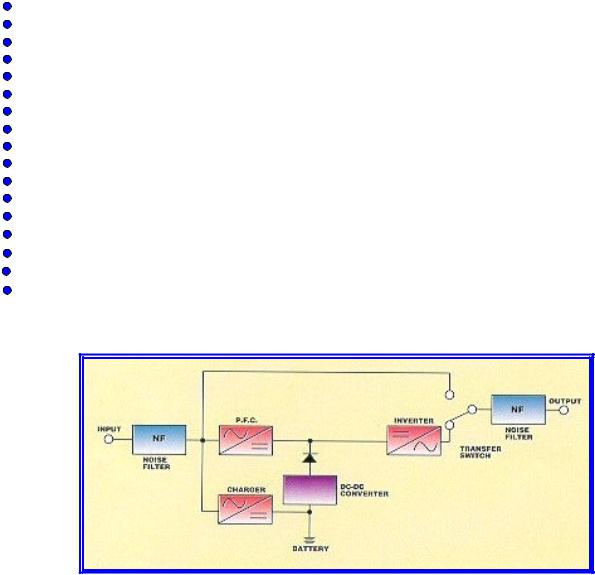
SG SERIES ON-LINE UPS SYSTEM BLOCK DIAGRAM
NOTE: All SG UPSs are constructed using metric screws, nuts and hardware.
1

IMPORTANT SAFETY INSTRUCTIONS
SAVE THESE INSTRUCTIONS
This manual contains important instructions which must be followed during the installation, operation and maintenance of this UPS and its batteries. Please read all instructions before operating this equipment and save this manual for future reference.
CAUTION
All of the models presented herein are designed for installation and use in a temperature controlled environment, free of contamination.
CAUTION
This UPS utilizes voltage that may be hazardous. Do not attempt to disassemble. This unit contains no user replaceable parts. Refer all servicing to Falcon
Electric, Inc.
CAUTION
THIS UPS IS NOT INTENDED TO BE USED IN CONJUNCTION WITH LIFE SUPPORT OR OPERATING ROOM EQUIPMENT.
CAUTION
Always turn off the input and battery circuit beakers prior to cleaning and never apply liquid or spray detergent on the UPS.
CAUTION
Never attempt to service batteries. High voltage exists within the unit, which could cause electrical shock. Servicing of batteries should be performed or supervised by personnel knowledgeable of batteries and the required precautions. Keep unauthorized personnel away from batteries. When replacing the UPS batteries, use the same number and type of batteries.
IMPORTANT
Allow at least 24 hours, after the UPS is first installed and turned on, to fully charge the internal battery and assure the maximum backup time is available.
DO NOT
DO NOT connect the input of this UPS to its own output, as this may damage the
UPS.
CAUTION
DO NOT remove or unplug the UPS input when it is turned on. This removes the safety ground from the UPS and the equipment connected to the UPS.
CAUTION
This UPS contains its own energy source (batteries). The output receptacles may carry live voltage even when the UPS is not connected to an AC source.
IMPORTANT
Should the SG Series UPS unit be stored for more than two weeks, it is mandatory that the battery circuit breaker be turned off prior to storage or battery damage will result.
2
CHAPTER 1
SG Series UPS - Overview
True Regenerative On-Line Design
As new and innovative technologies have become the backbone of today's businesses, maximum system availability is critical and downtime is more expensive than ever. Increasingly, businesses need a UPS that not only protects against blackouts, but also virtually eliminates more frequent and subtle power disturbances. Surges, sags, line noise and brownouts can disrupt proper operation of sensitive equipment. These disturbances may also create unnecessary production, service, and data recovery costs.
A True Regenerative On-Line UPS provides the highest level of protection against the widest spectrum of power problems. The incoming AC utility source is converted to a regulated DC voltage. From this DC voltage, a new AC voltage is regenerated, providing continuous, clean, tightly regulated power to your equipment. Line-interactive and Off-line designs leave your equipment connected directly to dirty utility power. They only provide minimal transient, voltage and backup protection. If your equipment operation is "Mission Critical", a true double conversion On-Line UPS, such as Falcon® Electric's SG SeriesTM UPS Plus®, is the only clear choice.
Input Power Factor Correction
All SG Series UPS Plus models include state-of-the-art Input Power Factor Correction. This greatly reduces the amount of current demanded from your building wiring system, yielding a highly efficient, "building friendly" UPS.
Microprocessor Control
Falcon Electric's SG Series UPS incorporates advanced microprocessor technology. This technology makes possible a high level of internal UPS control and management. With the supplied UPSILON® software, all SG Series UPS models support unattended shutdown, management, data logging, and self-diagnostics. The software supports MS Windows® 95, 98, NT, 2000, 2000 Server, ME, XP, Novell Netware® 5 & 6, LINUX and FreeBSD. UPSILON for UNIX may be purchased seperately and supports most popular UNIX platforms and OS versions.
SNMP/HTTP Remote Management Support
Our SNMP/HTTP Agent board provides remote management and monitoring over any Ethernet LAN, WAN or the Internet utilizing a 10BaseT-type connection. The optional SNMP/HTTP agent installs via an option slot located behind a cover plate on the back panel of every SG Series model.
Extended Battery Bank Option
All SG Series models have a continuous duty inverter and support the addition of optional external battery/charger packs. Whether your application requires a few additional minutes or hours, the SG Series will be ready. Falcon also offers optional battery charger upgrades for faster recharging. Please specify your extended battery and charger requirements at the time of your initial order.
Frequency Converter Option
With a factory modification at the time of order, any SG Series model can be configured for use as an international frequency converter. This makes the SG Series UPS Plus an ideal choice for worldwide power applications. Without this modification, all SG series models will detect the incoming utility line frequency and automatically set its output frequency to match.
3

CHAPTER 2
INSTALLATION INSTRUCTIONS
General - Common for all models
1.Verify the following is included in the UPS shipping carton:
(1) UPS, (1) Software Diskette(s) & Manual, (1) Owners Manual & (1) UPS/Computer Cable.
2.Verify the UPS unit is configured for the proper input/output voltage and frequency. This information is stated on the nameplate label located on the rear or the side panel of the unit. If any special input plug and output receptacle configurations were specified at the time of order, verify for proper configuration.
3.Set the output voltage and green mode switches located on the UPS rear panel for the nominal UPS output voltage desired. See the switch setting tables located on
page 5.
In most cases the nominal UPS output voltage should be set to match the incoming utility voltage. This will assure a close matching voltage in the event the UPS is placed on bypass. NOTE: Disregard the "ON" marking on the side of the actual dip switch housing; use the tables in this manual or the silkscreen on the UPS rear panel only.
Dip switch 3 "enables" or "disables” the "Green Mode" function. The UPS is shipped from the factory with the switch set in the "disabled" position (up). If SW3 is switched down or to the "enabled" position, the Green Mode function is activated. When the
load connected to the output of the UPS drops to under 10% of the full rated UPS output for 30 seconds, the UPS is automatically placed into bypass and the inverter is turned off.
NO BATTERY BACKUP IS PROVIDED AFTER THE GREEN MODE HAS ACTIVATED.
Dip switch settings must be made while the UPS is turned off. Any changes made while the UPS is turned on will not take effect until the UPS is turn off and back on again since the switch settings are read by the microprocessor only during initial UPS power up.
4.To prevent accelerated battery discharge during shipment, this UPS was shipped with the battery circuit breaker turned off. TURN THE BATTERY DISCONNECT CIRCUIT BREAKER ON PRIOR TO TURNING ON THE UPS INPUT CIRCUIT BREAKER.
CAUTION
NEVER TURN THE BATTERY CIRCUIT BREAKER OFF WHILE THE UPS AC CIRCUIT BREAKER IS TURNED ON AND OPERATING FROM THE UTILITY VOLTAGE, OR UPS DAMAGE MAY RESULT. UPS MUST BE COMPLETELY SHUT DOWN PRIOR TO DISABLING THE INTERNAL BATTERY SUPPLY.
CAUTION
In the event this UPS is to be turned off or stored for more than two weeks, the battery circuit breaker must be turned to the off position to prevent battery discharge. If placed in long-term storage, every four months the UPS must be plugged in and turned on for 24 hours to allow the batteries to recharge and prevent battery damage. Failure to follow these procedures will invalidate your warranty.
4

VIEW OF OUTPUT VOLTAGE & GREEN MODE SELECT SWITCHES
(LOCATED ON THE UPS REAR PANEL)
OFF = 0
Disregard
“ON” Designation
DIP
SWITCHES
ON = 1 |
|
SELECTION |
|
|
TABLE |
|
|
|
|
|
|
SWITCH SETTINGS FOR ALL MODELS
SW2 |
SW1 |
|
OUTPUT VOLTAGE 1 |
OUTPUT VOLTAGE 2 |
|||
|
|
|
|
|
(All models) |
(-TX & -TXC models only) |
|
Down |
Down |
|
|
208 Vac |
115 Vac |
||
Down |
Up |
|
|
220 Vac (default) |
120 Vac |
||
Up |
Down |
|
|
230 Vac |
125 Vac |
||
Up |
Up |
|
|
240 Vac |
130 Vac |
||
|
GREEN MODE SWITCH SETTINGS FOR ALL MODELS |
||||||
|
|
|
|
|
|
|
|
|
|
SW3 |
|
FUNCTION |
|
|
|
|
|
Down |
|
GREEN MODE ON |
|
|
|
|
|
Up |
|
GREEN MODE OFF |
|
|
|
5
6.Select a suitable location for the UPS.
VERIFY THE FLOOR OR SURFACE SUPPORTING THE UPS WILL SUPPORT THE
WEIGHT OF THE UPS AND ANY OPTIONAL EXTENDED BATTERY BANKS.
SG5K-2T & SG6K-2T UPS MODELS = 216 lbs. (98 kg) SG5K-2TC & SG6K-2TC UPS MODELS = 239 lbs. (108 kg)
SG5K-1TX, SG5K-2TX, SG6K-1TX, SG6K-2TX UPS MODELS = 299 lbs. (136 kg) SG5K-1TXC, SG5K-2TXC, SG6K-2TXC UPS MODELS = 322 lbs. (146 kg)
FLOOR STANDING EXTENDED BATTERY BANKS = 363 lbs. (165 kg) MAX. (EACH BANK)
7.If extended battery banks are to be connected to the UPS, please refer to page 7 for hardwire models and page 16 for all other models.
8.If unattended computer shutdown and monitoring are desired, connect the green UPS/Computer cable to the DB-9 connector located on the UPS rear panel. Then install the shutdown and monitoring software provided with the UPS. For your reference, UNIX shutdown and monitoring software is available from Falcon Electric at an additional cost.
9.Verify the location selected has adequate ventilation to allow for the proper cooling of the UPS.
DO NOT BLOCK UPS FANS OR AIR VENTS. THE UPS MUST NOT BE INSTALLED IN AN ENCLOSED AREA.
10.For further installation instructions covering hardwire models SG5K-1TX, SG5K-2T, SG6K-1TX, SG6K-2T and SG6K-2TX, please refer to page 7.
11.Lower the leveling feet.
a.Verify the flooring at the UPS or battery bank installation location is rated for the weight of the equipment.
b.Roll the UPS or extended battery bank to the final installation location.
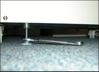
c.Locate the position of the (4) levelling feet underneath the UPS near its four corners. (see picture below).
d.Using your fingers and a 12mm open end wrench, screw the levelling feet in a clockwise direction, lowering the feet until all four feet are securely against the floor.
12.For further installation details covering the following models having a line cord and PDU, please refer to page 13. Models SG5K-1TXC, SG5K-2TC, SG5K-2TXC,
SG6K-2TC and SG6K-2TXC.
Leveling Feet Adjustment
6

Installation Instructions For Hardwire Models (see model numbers referenced below)
1.0UPS Input & Output Requirements.
IMPORTANT
Note: All SG Series hardwire UPS models must be installed by a licensed electrician, in accordance with the National Electrical Code (NEC) ANSI/NFPA70 and all local regulations. It is further required that the input of SG Series hardwire UPS be wired to a building service panel incorporating a dedicated “branch rated” circuit breaker of the proper rating.
|
|
|
INPUT REQUIREMENTS |
|
|||
|
|
MODEL |
|
|
REQUIRED INPUT |
||
|
|
|
|
|
|
CIRCUIT BREAKER |
|
SG5K-1TX:- 120Vac, 50/50Hz, 38.7A, 1 phase, 3 wire |
|
50A |
|||||
SG5K-2T - 208-240Vac, 50/60Hz, 19.5A, 1 phase, 3 wire |
|
30A |
|||||
SG5K-2TX - 208-240Vac, 50/60Hz, 20.3A, 1 phase, 3 wire |
30A |
||||||
SG6K-1TX - 120Vac, 50/60Hz, 46.6A, 1 phase, 3 wire |
|
70A |
|||||
SG6K-2T - 208-240Vac, 50/60Hz, 23.4A, 1 phase, 3 wire |
|
30A |
|||||
SG6K-2TX - 208-240Vac, 50/60Hz, 24.3A, 1 phase, 3 wire |
30A |
||||||
|
|
|
|
|
|
|
|
|
|
|
WIRE GAUGE CHART |
|
|
||
|
|
MODEL |
AC INPUT |
AC OUTPUT(S) |
EXTERNAL |
||
|
|
|
-1 = 120 Vac |
120 Vac |
208-240 Vac |
BATTERY |
|
|
|
|
-2 = 208-240 Vac |
|
|
|
240 dc |
|
|
|
|
|
|
|
|
|
|
SG5K-1TX |
8 Awg. 600V |
10 Awg. 600V |
|
12 Awg. 600V |
10 Awg. 600V |
|
|
|
75°C CU |
75°C CU |
|
75°C CU |
75°C CU |
|
|
SG5K-2T |
12 Awg. 600V |
N/A |
|
12 Awg. 600V |
10 Awg. 600V |
|
|
|
75°C CU |
|
75°C CU |
75°C CU |
|
|
|
|
|
|
|||
|
|
SG5K-2TX |
12 Awg. 600V 75°C |
10 Awg. 600V |
|
12 Awg. 600V |
10 Awg. 600V |
|
|
|
CU |
75°C CU |
|
75°C CU |
75°C CU |
|
|
SG6K-1TX |
6 Awg. 600V |
8 Awg. 600V |
|
10 Awg. 600V |
10 Awg. 600V |
|
|
|
75°C CU |
75°C CU |
|
75°C CU |
75°C CU |
|
|
SG6K-2T |
10 Awg. 600V |
N/A |
|
10 Awg. 600V |
10 Awg. 600V |
|
|
|
75°C CU |
|
75°C CU |
75°C CU |
|
|
|
|
|
|
|||
|
|
SG6K-2TX |
10 Awg. 600V 75°C |
8 Awg. 600V |
|
10 Awg. 600V |
10 Awg. 600V |
|
|
|
CU |
75°C CU |
|
75°C CU |
75°C CU |
|
|
External Battery & |
16 Awg, 600V |
N/A |
|
N/A |
10 Awg. 600V |
|
|
Charger System |
75°C CU |
|
75°C CU |
||
|
|
|
|
|
|||
ONLY USE WIRE WITH SOLID COPPER CONDUCTORS FOR ALL INPUT/OUTPUT/BATTERY WIRING
SCREW TORQUE SPECIFICATIONS FOR
INPUT/OUTPUT WIRING BLOCK
UPS & BATTERY BANK
|
|
Wire Gauge |
Torque |
|
|
|
(inch pounds) |
|
|
18 - 10 Awg. |
20 |
|
|
8-6 Awg |
25 - 30 |
CAUTION
To reduce the risk of fire, connect only to a circuit providing over-current protection incorporating the specified "branch rated" over-current protection device in accordance with the National Electrical Code, ANSI/NFPA 70.
7
 Loading...