Fagor NC-200 PB User Manual

FAGOR NC-200 PB
NC FOR
PRESS BRAKES
OPERATING MANUAL
Manual version 0111

|
INDEX |
|
Diagram of a typical press BRAKE ..................................................................... |
0 |
|
Introduction ....................................................................................................... |
1 |
|
Description of the various machine models .......................................................... |
1 |
|
1. |
Unit description .................................................................................... |
2 |
1.1 |
Front panel ............................................................................................. |
2 |
2. |
Coordinate display. Auxiliary modes ................................................... |
4 |
2.1 |
Display modes ........................................................................................ |
5 |
2.2 |
Selection of tools and types of material to bend ....................................... |
6 |
2.3 |
Type of material...................................................................................... |
7 |
2.3.1 |
Generate the whole elasticity factor table for a new unknown material........ |
9 |
2.3.2Generate the elasticity factor of a single angle by testing
|
the bending depth .................................................................................. |
10 |
2.3.3 |
Generate the elasticity factor by trial and error and correct the angle ......... |
12 |
2.3.4 |
Saving and recalling the material-type tables through |
|
|
the serial line RS-232 ............................................................................. |
13 |
2.3.5 |
Restoring initial tables ............................................................................ |
14 |
3 |
Operating modes ................................................................................ |
14 |
3.1 |
Manual /set mode .................................................................................. |
14 |
3.1.1 |
Manual movement from the NC keyboard ............................................... |
15 |
3.1.2 |
Movement with the foot switches. "C" model ......................................... |
15 |
3.1.3 |
Manual movement to a particular "X" position, "Y" depth or "a" angle .... |
16 |
3.1.4 |
Manual movement by external means ...................................................... |
16 |
3.2 |
Machine reference (home) search ........................................................... |
17 |
3.2.1 |
Sequence for axes with mandatory home search on power-up ................. |
17 |
3.2.2 |
Sequence for axes without mandatory home search ................................. |
18 |
3.2.3 |
Sequence for the Y axis. Model B .......................................................... |
18 |
3.3 |
Tool table loading .................................................................................. |
19 |
3.3.1 |
Recall initial tool values .......................................................................... |
19 |
Operating Manual NC-200 PB

4 |
Programming ..................................................................................... |
20 |
4.1 |
Program editing ..................................................................................... |
20 |
4.1.1 |
Editing / Deleting an existing program ..................................................... |
20 |
4.1.2 |
Editing a new program ........................................................................... |
22 |
4.2 |
Inserting / deleting blocks in a previously edited program ........................ |
27 |
4.3 |
Deleting all the programs ........................................................................ |
27 |
5 |
Execution Modes with control from the foot switches and |
|
|
manual station. Models A1, B, C ....................................................... |
28 |
5.1 |
Program execution ................................................................................. |
30 |
5.2 |
Execution in semiautomatic mode........................................................... |
32 |
6 |
Operation with the RS-232-C serial line ........................................... |
32 |
6.1 |
Saving and restoring data ....................................................................... |
32 |
6.2 |
Parameter transmitting format ................................................................. |
33 |
6.3 |
Program transmitting format ................................................................... |
33 |
6.4 |
Transmission of material-type tables ....................................................... |
33 |
Appendix ........................................................................................................ |
34 |
|
Error codes ...................................................................................................... |
34 |
|
Maintenance...................................................................................................... |
35 |
|
NC-200 PB Operating Manual
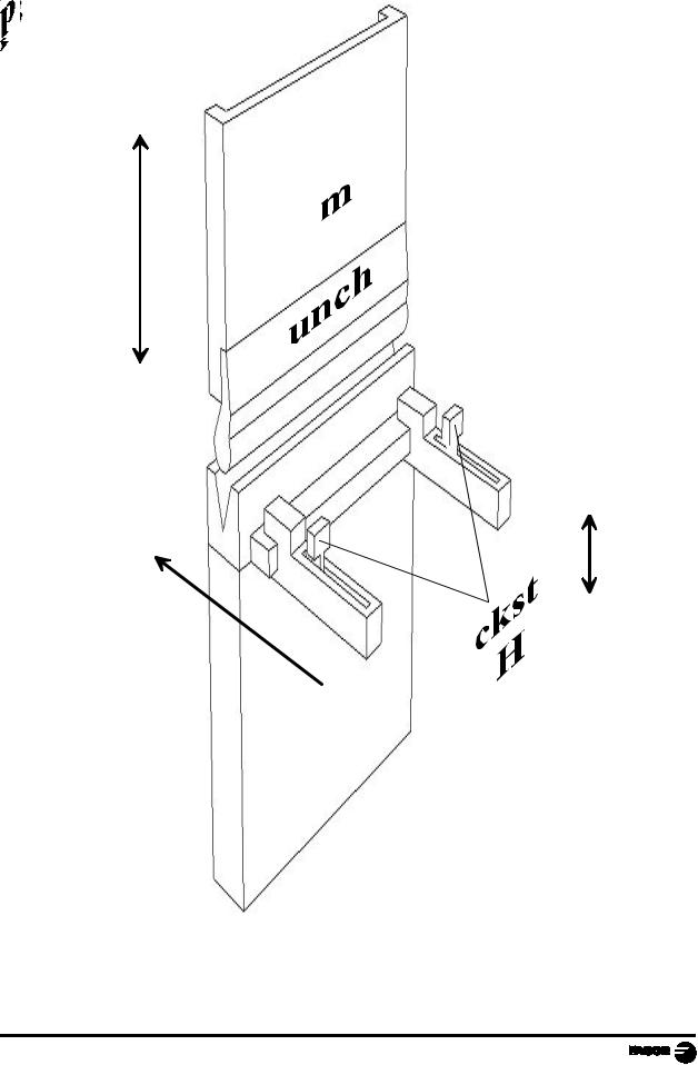
DIAGRAM OF A TYPICAL PRESS BRAKE
+
Y
-
-
X  +
+
Operating Manual NVP-200 PB - page 0 -

INTRODUCTION
Throughout this manual, certain installation parameters are referred to which affect the description of certain NC functions.
These parameters have been set by the installer and may be modified by the operator.
These parameters are described in the installation manual supplied with this unit.
DESCRIPTION OF THE VARIOUS MACHINE MODELS
This manual mentions different machine models (A, A1, B, C) that are built quite differently; but they don't differ as much when using the resources of this numerical control whether they are up-stroke or down-stroke models.
A.Controlling only the final position of the bend for simple machines that do not require distinguishing 4 execution modes.
The foot switches, the execution modes and the hydraulic circuit are not handled by this unit.
The intermediate positions of the ram cannot be preset.
They are detected with electrical micro-switches.
A1. Same as model A with foot switch control and outputs to control the hydraulic valves handling the 4 EXECUTION modes.
Especially indicated for conventional down-stroke machines.
B.Same as model A1 with a linear feedback or digital potentiometer to read the actual position of the ram or the table. This allows detecting the intermediate positions that may be selected at the NC:
-Top dead point. FAST/SLOW change position.
-FAST/SLOW change position.
-Sheet metal holding position. End of the bend.
Very useful for up-stroke models.
C.Control of the actual movement of the ram / table / apron and presetting of intermediate positions.
NC-200 PB - Operating Manual - Page: 1
1.UNIT DESCRIPTION
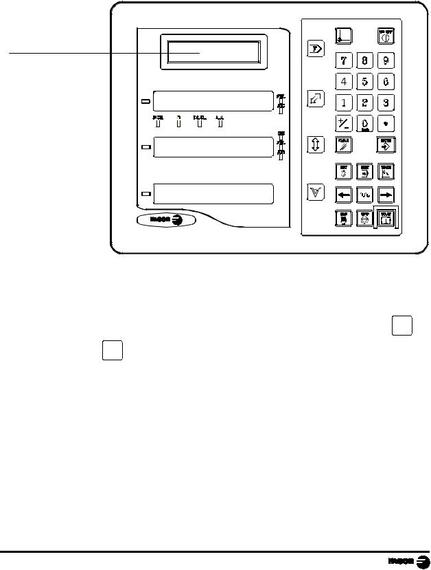
This NC is especially designed to be used on press brakes. It allows displaying the position of the vertical and horizontal axes as well as executing partprograms and also moving the axes manually from this NC's keyboard or by external means.
1.1FRONT PANEL
Message display
The message display offers assistance to facilitate the operating modes of
this NC.
When using an LCD screen, its contrast may be adjusted by pressing 3 to decrease it or 9 to increase it.
Page: 2 - Operating Manual - NC-200 PB
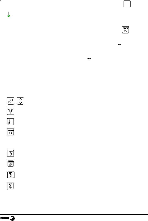
Each axis display has eight 14.1 mm high LEDs and another one for the minus sign (-).
INCH- Inch mode selection. To access it or quit it, press 0
inch
Machine reference search mode which is accessed by selecting the SET mode.
TEACH - TEACH-In mode which is accessed by pressing |
|
|
|
when the |
editing mode is selected (on the screen for coordinate selection).
MAN - Manual mode which is accessed by pressing  There are two ways to access it:
Models A and B . Using the  key Model C - By selecting the SET mode.
SEL - Axis selected.
JOG - Axis moving.
DIS - Y axis disabled (selector switch in position 5).
Select the X and Y axis respectively.
Program the bending angle or the width of the die's "V".
Machine reference zero (home) search.
Turn the display off while keeping track of the axes position at all times.
This key must be pressed before turning the unit's power off by the main switch on the back of the unit.
Validate an operation.
Cancel or abort an operation already initiated.
Access the program or tool editing mode.
Access the manual mode.
NC-200 PB - Operating Manual - Page: 3
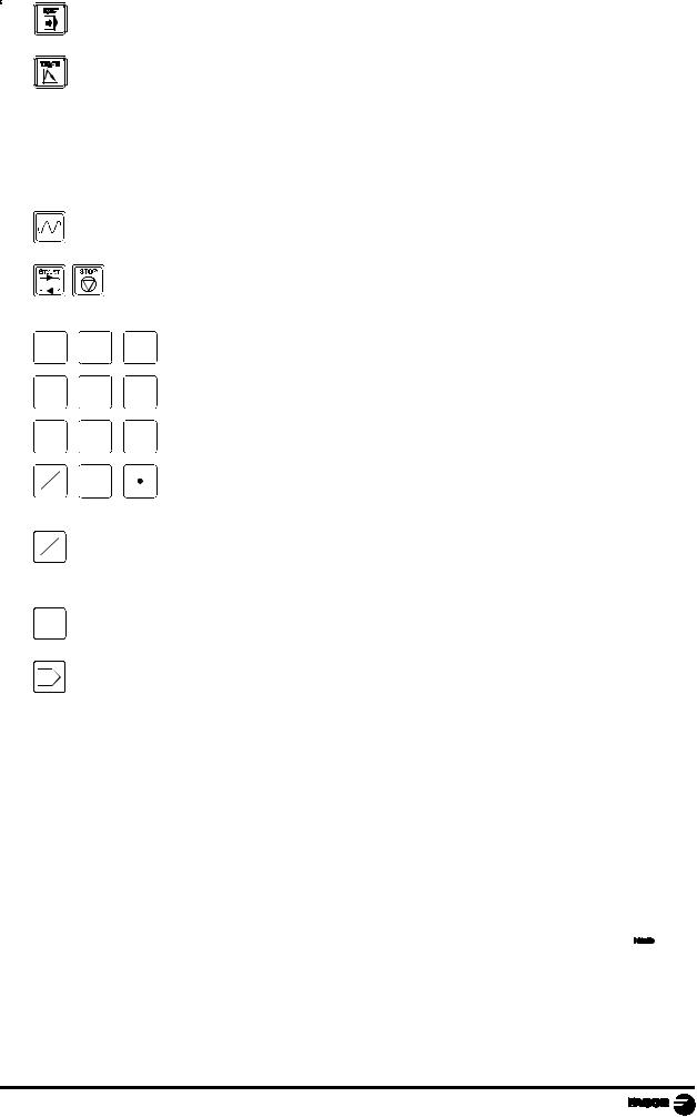
Access the program execution mode.
Program blocks after moving the axes to the desired position while in editing mode (Teach-in mode).

 Move the axes in MANUAL mode in both directions and to move back and forth from one menu option to another.
7
4
1
+
-
+
-
Move the axes manually at fast feedrate.
Execute and interrupt, respectively, the execution of a program.
8 9
5 6
Enter data.
2 3
0
inch
Change the sign of the value being entered and to eliminate the last digit of the X and Y axes.
0 Toggle between metric and inch display.
inch
FAccess the special operation modes, parameter setting, communications via RS-232-C, etc.
2.COORDINATE DISPLAY. AUXILIARY MODES
Turning the unit ON
The unit is turned on by actuating on the power switch of the rear panel
This NC runs a self-test and its LCD screen shows the text:
Fagor NC-200 PB, the 1st and 2nd displays show "Fagor NC". Press and if there is an error, the displays will show the error number if otherwise. See the appendix at the end of this manual.
Page: 4 - Operating Manual - NC-200 PB
Turning the unit OFF
If you press


 key the NC turns off the displays while maintaining the power supply to the feedback systems and goes on reading the position of the axes at all times. This is not the case when the equipment is turned off by means of the switch on the rear panel of the same.
To reset the displays, just press this key again as long as that the NC is getting voltage (plugged in and with the switch on the rear panel on).
Notes:
-Before powering the NC down with the switch on the rear panel or disconnecting
it from mains, it is a good idea to press the


 key in order to store the current position of the axes permanently.
-If the unit is powered down with its rear panel switch or there is a power outage
without previously having pressed 


 , the NC will keep the last position of the axes for at least 30 minutes.
-The unit will display ERROR 2 when powered back up if the position reading was lost when turned off while the axes were moving or after the accidental backup period has expired without having saved the current position by previously pressing 


 .
.
2.1DISPLAY MODES
Language selection
On this NC, it is possible to select the language used for displaying the help on the LCD screen. To do this:
- |
Access parameter PAR50 (language) directly by pressing |
|
5 |
0 |
||
|
|
|
|
|
|
inch |
- |
Press + |
- |
repeatedly until the desired language appears (English, Spanish, |
|||
|
|
|
|
|
|
|
French, German, Italian, Portuguese, custom*) and press  . Press
  to quit the language selection mode.
"Custom" may be any user defined language. (See section 3.4 PAR52 of the installation manual).
NC-200 PB - Operating Manual - Page: 5
Conversion mm into inches
This NC can displayed the position of the axes in millimeters or inches by
pressing 0 key depending on whether theINCHled is off or on respectively..
inch
Turning off the last digit of the X and Y displays
This NC allows a decimal digit to be switched off (coarse resolution) when the resolution is excessive, simply by pressing + - . For example 0.01 instead of 0.012.
2.2SELECTION OF T OOLS AND TYPES OF MATERIAL TO BEND
In the initial mode, it is possible to set a particular punch-die set and also the bending pressure as well as the characteristics of a particular material.
This data will only be assumed when machining in MANUAL mode. Section 3.1.
· Press F
·Use to select <Tool> and press
 to access to the selection page:
 [punch number] [·] [die number] and press
 Maximum pressure when using a pressure gage (transducer),
 [Sheet thickness]
 [Number of associated table (0 to 19)]
 Press
Press to exit.
This unit assumes the offsets indicated in the tool table. See section 3.3.
·The screen shows the number of the selected tooling.
Punch, die 1.1
·The position shown on the Y axis display corresponds to the relative distance between the edge of the punch and the top side of the die.
The final bend position is always negative.
Page: 6 - Operating Manual - NC-200 PB

2.3TYPE OF MATERIAL
The type of material depends on a number of factors that make it impossible to foresee its behavior in order to calculate the depth "Y" of the punch according to the programmed angle α.
This problem is solved using the TEACH-IN editing mode that forces the operator to make several bends by trial and error until obtaining an acceptable result and memorize the "Y" depth associated with the requested angle α.
This is a very time-consuming task because it has to be repeated for all the programmed angles. A program stored in memory must be executed with the same tools used in the TEACH-IN process. The width of the die forces its geometry.
Using the elasticity factor associated with each material exceeds the capabilities of a conventional TEACH-IN editor that only requests the depth of the bend:
·It is a programmable parameter that is assumed together with the thickness of the sheet metal in the N0 block of each program.
·It associates certain constants, in a table format, for 8 fixed values multiple of 10 between 50º and 120º.
·It calculates (prorates) the factor corresponding to intermediate angles.
·It is also possible to store in the table 5 special values associated non-multiple of 10 or out of the 50º-to-120º range, if they will be repetitive in future bends with the same material.
·The TEACH-IN editor (section 4.1.2) offers the option to load a new factor for special angles or modify the value stored in the table that matches a typical angle to be corrected.
·This unit has resources to generate the tables for unknown material types and to set corrections based on the original ones to adapt them to materials supposedly very similar to the standard ones offered here and described in later chapters.
·For white sweet sheet metal F114 (resistance < 50 Kg), the factor is barely affected by the width of the die. The same program may be executed with different tools with results very similar results as for the mentioned materials and similar punch radii. It will only require a slight correction.
If the A aperture of the die is larger than the one used in the tries, the resulting angle will be slightly greater.
NC-200 PB - Operating Manual - Page: 7
By default, this unit has some initial tables stored in nonvolatile memory and cannot be modified. This table may be used as a sample for typical materials and there is a modifiable copy of this table under factor numbers M0 to M19.
Either the non-modifiable factors M21 through M41 or the modifiable ones M0 through M20 when programming the header page N0.
There is a specific way, section 2.3.3, to recover the initial tables that serve as a reference and correspond with the following materials and tools where:
Punch radius of 1 mm:
A = Die width
r = Die edge radius
e = Material thickness
Ri = Inside bending radius.
In order to obtain the same results with the suggested tables, we recommend to use dies with an edge radius r = A/10 and an aperture A = 8 x e. On sweet steel, Ri = A/6
|
Material |
A |
r |
e |
M0 |
Reserved for inflexible materials |
|
|
|
M1 |
Aluminum |
12 |
1 |
1 |
M2 |
Aluminum |
16 |
1.5 |
1.5 |
M3 |
Aluminum |
20 |
2 |
2 |
M4 |
Aluminum |
24 |
2.5 |
3 |
M5 |
Reserved |
|
|
|
M6 |
White sheet < 48 Kg mm2 |
12 |
1 |
1 |
M7 |
White sheet < 48 Kg mm2 |
16 |
1.5 |
1.5 |
M8 |
White sheet < 48 Kg mm2 |
16 |
1.5 |
2 |
M9 |
White sheet < 48 Kg mm2 |
20 |
2 |
2.5 |
M10 |
White sheet < 48 Kg mm2 |
24 |
2.5 |
3 |
M11 |
Reserved |
|
|
|
M12 |
Reserved |
|
|
|
M13 |
Reserved |
|
|
|
M14 |
Reserved |
|
|
|
M15 |
Stainless steel |
12 |
1 |
0.5 |
M16 |
Stainless steel |
12 |
1 |
0.75 |
M17 |
Stainless steel |
12 |
1 |
1 |
M18 |
Stainless steel |
16 |
1.5 |
1.5 |
M19 |
Stainless steel |
16 |
1.5 |
2 |
Page: 8 - Operating Manual - NC-200 PB
 Loading...