


FAGOR NC-200 PB
NC FOR
PRESS BRAKES
INSTALLATION MANUAL
Manual version: 0111

|
INDEX |
|
Declaration of conformity ................................................................................... |
4 |
|
Safety conditions ............................................................................................... |
5 |
|
Warranty terms ................................................................................................... |
7 |
|
Material returning terms ...................................................................................... |
8 |
|
Description of the different models (they may be selected with PAR64) ................ |
9 |
|
Diagram of a typical press brake ....................................................................... |
10 |
|
1. |
Unit description .............................................................................. |
11 |
1.1 |
Front panel (See operation manual) ..................................................... |
11 |
1.2 |
Rear panel ......................................................................................... |
11 |
1.3 |
General technical characteristics......................................................... |
12 |
2. |
Connections and characteristics .................................................... |
13 |
2.1 |
connection of the feedback systems ................................................... |
13 |
2.2 |
Input/Output characteristics (X2) ....................................................... |
14 |
2.3 |
Input/output Connection (X2). ........................................................... |
15 |
2.3.1 |
Input description. .............................................................................. |
15 |
2.3.2 |
Output description ............................................................................ |
17 |
2.3.3 |
Input/output connection .................................................................... |
18 |
2.3.3.1 |
Input/output connection. Model A ..................................................... |
18 |
2.3.3.2 |
Input/output connection. Model A1 ................................................... |
19 |
2.3.3.3 |
Input/output connection. Model B ..................................................... |
20 |
2.3.3.4 |
Input/Output connection. Model C .................................................... |
21 |
2.3.4 |
Block change synchronism. Models A, A1 ......................................... |
22 |
2.3.5 |
Block change synchronism. Model B ................................................. |
24 |
2.4 |
Machine reference (home) search....................................................... |
26 |
2.4.1 |
X axis home search ........................................................................... |
26 |
2.4.2 |
Y axis reference (home) search. Models A and A1 ............................. |
27 |
2.4.3 |
Y axis home search. Model "B" ......................................................... |
28 |
2.4.4 |
Y axis home search. Model "C" ......................................................... |
29 |
2.4.5 |
Precautions when home searching ...................................................... |
30 |
2.5 |
RS-232-C connection (connector X7) ............................................... |
31 |
2.6 |
Power and machine connection.......................................................... |
32 |
2.7 |
Turning the unit on and off ................................................................ |
32 |
3. |
Installation Parameters .................................................................. |
33 |
3.1 |
Parameter setting ............................................................................... |
34 |
Page: 2 - Installation Manual - NC-200 PB
4. |
Operation with the RS-232-C serial line ....................................... |
49 |
4.1. |
Saving and restoring data ................................................................... |
49 |
4.2 |
Parameter transmitting format ............................................................. |
49 |
5 |
SETUP ............................................................................................ |
50 |
5.1 |
Test mode ......................................................................................... |
50 |
5.1.1 |
Direct access to the parameters .......................................................... |
53 |
5.2 |
Axis setting........................................................................................ |
54 |
5.2.1 |
Open loop without analog voltage output. P46(3)=0, P46(5)=0 ............ |
54 |
5.2.2 |
Open loop with analog voltage output. PAR46(3)=1, PAR46(5)=0 ....... |
55 |
5.2.3 |
Closed loop. PAR 46(3)=1, PAR46(5)=1 ............................................ |
55 |
Appendix ........................................................................................................ |
57 |
|
Error codes ...................................................................................................... |
57 |
|
Maintenance...................................................................................................... |
58 |
|
Warning:
Before starting up the DRO, carefully read the instructions of Chapter 2 in the Installation Manual.
The DRO must not be powered-on until verifying that the machine complies with the "89/392/CEE" Directive.
NC-200 PB - Installation Manual - Page: 3

DECLARATION OF CONFORMITY
Manufacturer: Fagor Automation, S. Coop.
Barrio de San Andrés s/n, C.P. 20500, Mondragón -Guipúzcoa (ESPAÑA)
We hereby declare, under our responsibility that the product:
NC Fagor NC-200 PB
meets the following directives:
SAFETY:
EN 60204-1 Machine safety. Electrical equipment of the machines.
ELECTROMAGNETIC COMPATIBILITY:
EN 50081-2Emission
EN 55011 Radiated. Class A, Group 1.
EN 55011 Conducted. Class A, Group 1.
EN 50082-2 Immunity
EN 61000-4-2 |
Electrostatic Discharges. |
EN 61000-4-4 |
Bursts and fast transients. |
EN 61000-4-5 |
Power surges |
EN 61000-4-11 |
Voltage fluctuations and Outages. |
ENV 50140 Radiofrequency Radiated Electromagnetic Fields. ENV 50141 Conducted disturbance induced by radio frequency
fields.
As instructed by the European Community Directives on Low Voltage: 73/23/EEC, on Machine Safety 89/392/EEC and 89/336/EEC on Electromagnetic Compatibility.
In Mondragón, on April 1st, 2001
Page: 4 - Installation Manual - NC-200 PB
SAFETY CONDITIONS
Read the following safety measures in order to prevent damage to personnel, to this product and to those products connected to it.
Fagor Automation shall not be held responsible for any physical or material damage derived from the violation of these basic safety regulations.
Do not open this unit
Only personnel authorized by Fagor Automation may open this unit.
Do not handle the connectors with the unit connected to AC power.
Before handling the connectors (mains, feedback, etc.) make sure that the unit is not connected to AC power.
Use proper Mains AC power cables
To avoid risks, use only the Mains AC cables recommended for this unit.
Avoid electrical overloads
In order to avoid electrical discharges and fire hazards, do not apply electrical voltage outside the range indicated in chapter 2 of this manual
Ground connection
In order to avoid electrical discharges, connect the ground terminals of all the modules to the main ground terminal. Before connecting the inputs and outputs of this unit, make sure that all the grounding connections are properly made.
Before powering the unit up, make sure that it is connected to ground
In order to avoid electrical discharges, make sure that all the grounding connections are properly made.
Ambient conditions
Respect the temperature and humidity ranges specified on the chapter about technical characteristics in this manual (1.3).
Do not work in explosive environments
In order to avoid risks, damage, do not work in explosive environments.
NC-200 PB - Installation Manual - Page: 5

Working environment
This unit is ready to be used in Industrial Environments complying with the directives and regulations effective in the European Community
Install the unit in the right place
It is recommended, whenever possible, to instal the DRO so its power switch of the back panel is at a distance between 0.7 m (27.5 inches) and 1.7 m (5.6 ft) off the floor and away from direct sunlight, hot air, coolants, chemical products, blows as well as from relays, or high electromagnetic fields (about 0.5m or 20 inches) that could damage it.
This unit complies with the European directives on electromagnetic compatibility. Nevertheless, it is recommended to keep it away from sources of electromagnetic disturbance such as.
-Powerful loads connected to the same AC power line as this equipment.
-Nearby portable transmitters (Radio-telephones, Ham radio transmitters).
-Nearby radio / TC transmitters.
-Nearby arc welding machines.
-Nearby High Voltage power lines.
-Disturbance generating elements of the machine.
-Etc.
Safety symbols
Symbols which may appear on the manual
WARNING. symbol
It has an associated text indicating those actions or operations may hurt people or damage products.
Symbols that may be carried on the product
WARNING. symbol
It has an associated text indicating those actions or operations may hurt people or damage products.
"ELECTRICAL SHOCK" symbol
It indicates that point may be under electrical voltage
"GROUND PROTECTION" symbol
It indicates that point must be connected to the main ground point of the machine as protection for people and units.
Page: 6 - Installation Manual - NC-200 PB

WARRANTY TERMS
WARRANTY
All products manufactured or marketed by Fagor Automation has a warranty period of 12 months from the day they are shipped out of our warehouses.
The mentioned warranty covers repair material and labor costs, at FAGOR facilities, incurred in the repair of the products.
Within the warranty period, Fagor will repair or replace the products verified as being defective.
FAGOR is committed to repairing or replacing its products from the time when the first such product was launched up to 8 years after such product has disappeared from the product catalog.
It is entirely up to FAGOR to determine whether a repair is to be considered under warranty.
EXCLUDING CLAUSES
The repair will take place at our facilities. Therefore, all shipping expenses as well as travelling expenses incurred by technical personnel are NOT under warranty even when the unit is under warranty.
This warranty will be applied so long as the equipment has been installed according to the instructions, it has not been mistreated or damaged by accident or negligence and has been manipulated by personnel authorized by FAGOR.
If once the service call or repair has been completed, the cause of the failure is not to be blamed the FAGOR product, the customer must cover all generated expenses according to current fees.
No other implicit or explicit warranty is covered and FAGOR AUTOMATION shall not be held responsible, under any circumstances, of the damage which could be originated.
SERVICE CONTRACTS
Service and Maintenance Contracts are available for the customer within the warranty period as well as outside of it.
NC-200 PB - Installation Manual - Page: 7

MATERIAL RETURNING TERMS
When returning the DRO, pack it in its original package and with its original packaging material. If not available, pack it as follows:
1.- Get a cardboard box whose three inside dimensions are at least 15 cm (6 inches) larger than those of the unit. The cardboard being used to make the box must have a resistance of 170 Kg (375 lb.).
2.- When sending it to a Fagor Automation office for repair, attach a label indicating the owner of the unit, person to contact, type of unit, serial number, symptom and a brief description of the problem.
3.- Wrap the unit in a polyethylene roll or similar material to protect it.
4.- Pad the unit inside the cardboard box with poly-utherane foam on all sides.
5.- Seal the cardboard box with packing tape or industrial staples.
Page: 8 - Installation Manual - NC-200 PB

DESCRIPTION OF THE DIFFERENT MODELS (THEY MAY BE SELECTED WITH PAR64)
A.Controlling only the final position of the bend.
The foot switches and the hydraulic circuit are not controlled by this NC. The intermediate positions of the ram are detected by electrical microswitches.
A1. Same as model "A" with footswitch treatment and outputs for governing the hidraulic valves for the 4 EXECUTION modes.
The rapid approach feed is not managed.
Especially indicated for conventional down-stroke machines.
B.Same as model "A" with a linear encoder or potentiometric scale for decoding the intermediate ram or bed positions affecting the bending approach speed and depth:
With outputs to relays or to a PLC: STOP - Top dead point overrun S9 Fast ram approach.
S29 Slow speed controlled by the footswitches.
S28 Ram retraction.
With internal processing: (without external output).
·Going through "Y=sheet thickness" position to withdraw the X axis.
·Bend position reached to start bending timing on upstroke models that do not have a presostat.
C- Control of the actual ram/bed position.
With internal processing of all the intermediate positions.
The footswitches control directly the position of the bending tool, Y axis.
NC-200 PB - Installation Manual - Page: 9
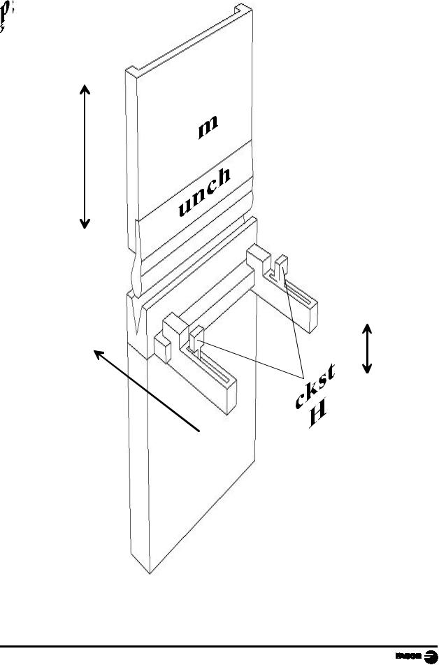
DIAGRAM OF A TYPICAL PRESS BRAKE
+
Y
-
-
X  +
+
Page: 10 - Installation Manual - NC-200 PB

1.UNIT DESCRIPTION
This unit is especially designed to be used on punch presses. It allows displaying the position of the X and Y axes, controlling them as well as the raising device (H), editing and executing part programs etc. The axes may also be moved manually from the dro keyboard or externally with footswitches.
1.1FRONT PANEL (SEE OPERATION MANUAL)
1.2REAR PANEL
1 |
2 |
3 |
Dimensions of the Built-in model (in mm):
On the back of the unit, the following items may be found:
1.- Power switch.
2.- Three-prong power connector for AC and ground connection.
3.- M6 mm terminal for general machine ground connection.
NC-200 PB - Installation Manual - Page: 11

X2.- SUB-D type 37 pin female connector to connect the digital inputs and outputs as well as the analog outputs.
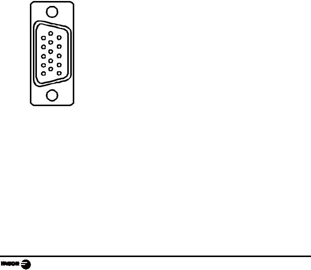
X3.- SUB-D HD type 15-pin female connector for X axis feedback device.
X4.- SUB-D HD type 15-pin female connector for Y axis feedback device.
X5.- SUB-D HD type 15-pin female connector for 2nd axis feedback device. auxiliary Y' axis (only on model "B").
X7.- SUB-D type 9 pin male connector for the RS-232-C serial line connection.
WARNING
Do not handle the connectors while the unit is under power. |
Before handling the connectors (mains, feedback, etc.) make |
sure that the unit is not under power. |
It is NOT enough to turn the display off by using the


 key at the keyboard.
1.3GENERAL TECHNICAL CHARACTERISTICS
Universal Power Supply between 100V AC and 240V AC ±10% at a mains frequency between 45 Hz and 400Hz, between 120Vdc and 300Vdc
Mains frequency of 0 Hz (DC) and from 45 Hz to 400 Hz.
Power outages of up to 20 milliseconds.
10-year memory backup of installation parameter even when the unit is off.
The operating temperature inside the DRO enclosure must be between 5º C and 45º C (41ºF and 113ºF).
The storage temperature inside the DRO enclosure must be -25º C and +70º C (-13º F and 158º F).
Maximum relative humidity: 95% non condensing at 45ºC (113ºF).
Front Panel Sealing: IP54 (DIN 40050), Rear panel: IP4X (DIN40050) except for built-in models in which case is: IP20.
Page: 12 - Installation Manual - NC-200 PB
2. CONNECTIONS AND CHARACTERISTICS
The connection for the RS-232 serial line (optional X1 connector) is not described in this manual; but in a supplement for it.
2.1CONNECTION OF THE FEEDBACK SYSTEMS
The feedback systems (scales or encoders) are connected via SUB-D HD type 15-pin female connectors: X3 and X4.
Characteristics of feedback inputs: X3, X4 and X5:
-+5V input consumption: 250 mA
-Admits square-wave signal (TTL). (A, B, Io)
-Maximum frequency: 250 KHz,
minimum separation between flanks: 950 nsec.
-Phase shift 90º ±20º, hysteresis 0.25 V, Vmax 7V, maximum input current: 3 mA.
- High threshold (logic state 1) |
2.4V < VIH < 5V |
|
||
- Low threshold (logic state 0) |
0.0V < VIL < 0.8V |
|||
|
|
|
|
|
|
Pin |
Signal |
|
Function |
|
|
|
|
|
|
1 |
A |
|
|
|
|
|
|
|
1 |
2 |
/A * |
|
Feedback signals |
|
|
|
|
|
|
3 |
B |
|
|
|
|
|
||
|
|
|
|
|
|
4 |
/B * |
|
|
|
|
|
|
|
|
5 |
Io |
|
Reference signal |
|
6 |
/Io * |
|
|
|
|
|
|
|
|
7 |
Alarm |
|
Feedback alarm |
|
|
|
|
|
|
8 |
/Alarm * |
|
|
|
|
|
||
|
|
|
|
|
|
9 |
+5V |
|
Power for feedback |
|
|
|
|
|
|
10 |
Not connected |
|
Not being used at this time |
|
|
|
|
|
|
11 |
0V |
|
Power for feedback |
|
|
|
|
|
|
12 |
Not connected |
|
Not being used at this time |
|
|
|
|
|
|
13 |
Not connected |
|
Not being used at this time |
|
|
|
|
|
|
14 |
Not connected |
|
Not being used at this time |
|
|
|
|
|
|
15 |
Chassis |
|
Shield |
|
|
|
|
|
* They depend on the type of feedback and may not be connected
NC-200 PB - Installation Manual - Page: 13

2.2 INPUT/OUTPUT CHARACTERISTICS (X2)
A 37-pin female connector is used.
Signal characteristics of connector "X2":
The supply voltage is at +24V (±25%), thus the threshold between a "0" and a "1" will be about +6V.
Characteristics of the inputs at 24V :
-Maximum load current: 100mA
-Minimum DC voltage: 18V
-Maximum DC voltage: 30V
The main characteristics of the digital outputs are:
(optocoupled with solid state relay with a normally open contact)
- Maximum AC or DC voltage: - Maximum load current:
- Maximum internal resistance: - Maximum peak current:
- Through current when open: - Leak current:
- Galvanic isolation voltage: - Activation time:
- Deactivation time:
Main characteristics of the analog outputs
Voltage range: |
±10V |
Resolution: 4.88mV |
|
Maximum current: |
10mA |
Offset: |
±30mV |
Impedance: |
120 Ohm referred to GND |
|
|
Page: 14 - Installation Manual - NC-200 PB

2.3INPUT/OUTPUT CONNECTION (X2).
Pin |
I/O |
Common signals |
Model "A" |
Model "A1" |
Model "B" |
|
Model "C" |
|
1 |
|
Chassis |
|
|
|
|
|
|
2 |
I |
0V External |
|
|
|
|
|
|
3 |
I |
24V External |
|
|
|
|
|
|
4 |
O |
24V User |
|
|
|
|
|
|
5 |
O |
X enable |
|
|
|
|
|
|
6 |
O |
1 = X fast, 0 = X slow |
|
|
|
|
|
|
7 |
O |
X direction |
|
|
|
|
|
|
8 |
I |
|
Not being used |
|
RETURN footswitch |
|
||
9 |
O |
|
Buzzer |
|
Fast approach |
|
Buzzer |
|
10 |
O |
Height H, 1 = up |
|
|
|
|
|
|
11 |
I |
X limit + (Io X) |
|
|
|
|
|
|
12 |
I |
X- limit |
|
|
|
|
|
|
13 |
I |
|
New block |
|
Not being used |
|||
14 |
I |
BCD 1 switch |
|
|
|
|
|
|
15 |
I |
|
Presostat |
|
Manual station |
|||
16 |
I |
External key 1 |
External key |
"BCD 2" EXECUTION mode selector |
||||
17 |
|
Chassis |
|
|
|
|
|
|
18 |
I/O |
Pressure or scale input |
|
|
|
|
|
|
X analog output |
|
|
|
|
|
|
||
|
|
|
|
|
|
|
|
|
19 |
I/O |
0V Analog. |
|
|
|
|
|
|
20 |
I |
0V External |
|
|
|
|
|
|
21 |
I |
24V External |
|
|
|
|
|
|
22 |
O |
24V User |
|
|
|
|
|
|
23 |
I |
Emergency |
|
|
|
|
|
|
24 |
O |
Y enable |
|
|
|
|
|
|
25 |
O |
1 = Y fast, 0 = Y slow |
|
|
|
|
|
|
26 |
O |
Y direction |
|
|
|
|
|
|
27 |
O |
Manual mode |
|
|
|
|
|
|
28 |
O |
|
|
Ram retract |
|
|
|
Not used |
29 |
O |
|
X, Y in position |
Feed ram |
|
Bend slowly |
|
Not used |
30 |
I |
Y limit + (Io Y) |
|
|
|
|
|
|
31 |
I |
Y- limit |
|
|
|
|
|
|
32 |
I |
|
X forward / retract |
|
X forward |
|
Not used |
|
33 |
I |
BCD 2 switch |
|
|
|
|
|
|
34 |
I |
Y disable |
|
|
|
|
|
|
Semiautomatic |
|
|
|
|
|
|
||
|
|
|
|
|
|
|
|
|
35 |
I |
|
External key |
|
BEND footswitch |
|
||
36 |
I |
|
External key |
"BCD 1" EXECUTION mode |
||||
37 |
O |
Y analog voltage |
|
|
|
|
|
|
2.3.1 INPUT DESCRIPTION.
Section 2.3.3 shows the electrical diagrams for the indicated models. The parameters mentioned there are described in chapter 3 of this manual.
The inputs are active high at 24V (PAR21 and PAR22 = 1....1).
Pin 18 may be configured as an analog input with a 0V to +10V range. When installing a linear potentiometer, it should be supplied with the 5V from the digital feedback devices (pin 5 of X3, X4).
NC-200 PB - Installation Manual - Page: 15

PIN |
FUNCTION |
|
|
|
|
DESCRIPTION |
||
|
|
In MANUAL mode, they limit the movement in the corresponding |
||||||
11, 12, |
Limit switches. |
direction. |
|
|
|
|
|
|
In EXECUTION mode, they abort the program. |
||||||||
30, 31 |
Hardware |
|||||||
|
|
In HOME SEARCH mode, they respond as home switches in the |
||||||
|
|
positive direction |
|
|
|
|||
|
|
|
|
|
|
|
|
|
23 |
EXTERNAL |
Disables the axes |
|
|
|
|||
Disables the outputs |
||||||||
EMERGENCY |
||||||||
|
Displays error 20 |
|
|
|
||||
|
|
|
|
|
||||
|
|
|
|
|
|
|
||
|
|
1 - Continuous feed |
||||||
14, 33, |
5-position BCD |
2, 3, 4 - Incremental feed with the pitch set by PAR 32 |
||||||
|
|
|
|
|
|
|||
selector in MANUAL |
5 - Y axis disable in EDITOR / TEACH-IN mode. It only displays it. It |
|||||||
34 |
||||||||
mode - PAR32 |
||||||||
|
allows withdrawing the punch by external means in "C" mode. |
|||||||
|
|
|||||||
|
|
Semiautomatic in EXECUTION mode |
||||||
|
|
|
|
|
|
|
||
|
|
|
|
|
|
|
||
|
Models A1, B and C |
|
36 |
16 |
|
|
||
36, 16 |
|
1 - RUN 1 |
0 |
|
0 |
|
|
|
"BCD" selector |
2 - RUN 2 |
0 |
|
1 |
|
|
||
|
3 - SET |
1 |
|
0 |
|
|
||
|
|
|
|
|
||||
|
|
4 - JOG |
1 |
|
1 |
|
|
|
|
|
|
|
|
|
|
|
|
35, 36, |
Model A |
|
|
|
|
|
|
|
External key |
Allows duplicating any 3 keys that may be selected - PAR 31 |
|||||||
16 |
||||||||
simulation. PAR 31 |
|
|
|
|
|
|
||
|
|
|
|
|
|
|
||
|
|
|
|
|
|
|
|
|
8, 35 |
Model A1, B and C |
They respond according to the logic defined with the "BCD" selector |
||||||
footswitch connection |
||||||||
|
|
|
|
|
|
|
||
|
|
|
|
|
|
|
||
|
Models A, A1 |
If PAR65.1=1, requires previous input at I32 |
||||||
13 |
Next block |
Confirmation of RAM at top dead position. Make sure that I13=1 to |
||||||
|
begin the home search (A, A1, B) |
|||||||
|
|
|||||||
|
|
|
|
|
|
|
|
|
|
Models A, A1 |
F1 - Retracts the backstop X if there 's a conflict when bending, |
||||||
|
Double function |
|||||||
|
conditioned by the editing attribute B in the slow speed stage |
|||||||
|
F1 + F2 |
|||||||
|
|
|
|
|
|
|
||
32 |
|
F2 - Forced X axis feed at the beginning of the bending sequence if |
||||||
|
PAR65.2 = 1 |
|
|
|
|
|
||
|
|
|
|
|
|
|
||
|
|
|
|
|
|
|
|
|
|
|
Only F2 |
|
|
|
|
|
|
|
Model B |
The X backstop automatically retracts at the position: |
||||||
|
|
Y = sheet thickness |
||||||
|
|
|
|
|
|
|
||
|
|
|
|
|
|
|
||
|
Model A, A1 |
A - Electrical signal from the pressure sensor |
||||||
|
|
A1 - Confirmation that the programmed maximum pressure has been |
||||||
|
Pressure sensor |
exceeded to begin the delay "D". |
||||||
|
section 2.3.4 |
Not connected. if the machine does not have a pressure sensor. |
||||||
15 |
|
|||||||
|
|
|
|
|
|
|
||
|
|
|
|
|
|
|
||
|
Mode B, C |
FAST approach before the bend conditioned to the maneouver safety |
||||||
|
that requires "busy hands". |
|||||||
|
|
|||||||
|
|
The change to SLOW is forced at a previous programmable position |
||||||
|
|
|
|
|
|
|
|
|
|
|
|
|
|
|
|
|
|
|
|
|
|
|
|
|
|
|
Page: 16 - Installation Manual - NC-200 PB

2.3.2 OUTPUT DESCRIPTION
If any of the outputs is going to be connected to some highly inductive device, a "1N4000" type diode must be installed in antiparallel. It is not required on auxiliary relays of less than 20 mA.
The drives are enabled with auxiliary relays (section 5.2).
P I N |
FUNCTION |
DESCRIPTION |
|
5, 6, 7, |
Axis enable |
|
|
FAST/SLOW |
Enabling drives or frequency inverters for open loop control. |
||
24, 25, 26 |
|||
DIRECTION PAR46 |
|
||
|
|
||
|
|
|
|
|
Analog voltage |
To control drives in closed loop drives. |
|
|
When installing a pressure transducer or potentiometric scale, |
||
18, 37 |
outputs. PAR 64, |
||
connect it to pin 18 and change the position of the internal |
|||
|
PAR65 |
||
|
jumper. |
||
|
|
||
|
|
|
|
|
|
|
|
27 |
MANUAL mode |
MANUAL mode selection confirmation. |
|
|
|
|
|
10 |
H output |
It activates the auxiliary output to raise the X axis backstop. R |
|
axis function, ON /OFF conditioned by the "H" editing attribute. |
|||
|
|
||
|
|
|
|
|
|
|
|
|
Models A, A1, B |
A - Retraction control by trigger time of the thermostat |
|
|
conditioned by the "D" attribute. |
||
28 |
|
||
|
|
||
Ram retraction. |
A1, B - Forced retraction up to the top dead point. Bending time |
||
|
|||
|
Section 2.3.4 |
conditioned by the "D" attribute. |
|
|
|
|
|
|
Model A |
Signal to the electrical cabinet to enable the FAST approach |
|
|
Axes in position |
buttons or SLOW bend footswitch. |
|
|
|
|
|
|
|
|
|
|
Model A1 |
Single output. |
|
|
Approach and |
The FAST/SLOW change is handled with external resources |
|
|
from the electrical cabinet that manages the FAST buttons and |
||
29 |
bending |
||
the change switch. |
|||
|
|
||
|
|
|
|
|
Model B |
At all models, it is reset with : |
|
|
SLOW approach. |
I32 (A, A1) or Y = e (B, C) at the beginning of the bend if |
|
|
attribute B |
||
|
Section 2.3.4 |
||
|
|
||
|
|
I15 when exceeding the bending pressure |
|
|
|
|
|
|
Model B |
|
|
|
Fast movement |
It resets in the programmable change position that forces the |
|
9 |
handling. Ram |
slow motion output O29. |
|
approach. |
|
||
|
|
||
|
|
|
|
|
Model A, A1, C |
Buzzer to warn the operator about "permission to bend" |
NC-200 PB - Installation Manual - Page: 17
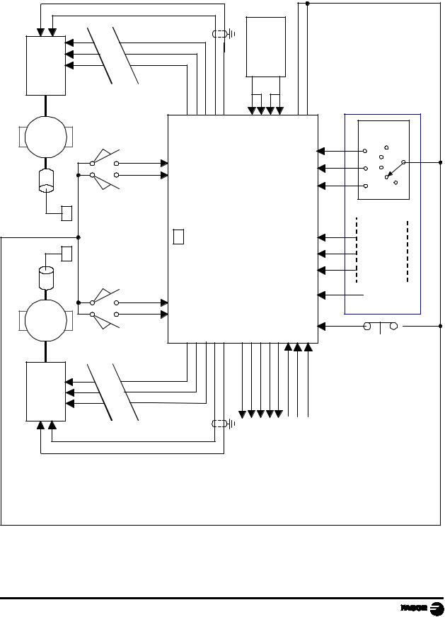
2.3.3 INPUT/OUTPUT CONNECTION
2.3.3.1 INPUT/OUTPUT CONNECTION. MODEL A
Without footswitch connection or ram controlling outputs.
|
|
|
|
|
|
|
|
|
|
|
|
|
|
|
|
|
24VUSER |
|
|
|
|
MOTOR CONTROL |
|
Y ENABLE |
Y SPEED |
Y DIRECTION |
ANALOG Y |
GNDA |
|
0V |
24V |
EXTERNAL |
24V |
|
|
|
|
|
|
|
|
|
|
|
24 |
25 |
26 |
37 |
19 |
|
2 |
20 |
|
3 |
21 |
4 |
22 |
|
Y Dis. |
Semiauto |
|
|
|
M |
|
|
|
34 |
x100 |
BCD |
|||||||||||||
Encoder |
|
LIMITY- |
30 31 |
|
|
|
|
PB |
|
|
|
|
|
|
14 33 |
x50 |
|
|
|
|
|
LIMITY+ |
|
|
|
|
|
|
|
|
|
|
x1 |
ß |
|
||||||
|
|
|
|
|
|
|
|
|
|
|
|
|
||||||||
|
X3 X4 |
|
X2 |
|
|
|
|
NC200 |
|
|
|
|
|
|
16 |
EXTERNAL |
KEY |
SIMULATION |
|
|
Encoder |
|
|
|
|
|
|
|
|
|
|
|
35 36 |
|
|||||||
|
|
|
12 |
|
|
|
|
|
|
|
|
|
|
|
|
8 |
FREE |
|
|
|
|
|
LIMITX- |
|
|
|
|
|
|
|
|
|
|
|
|
|
|
|
|
|
|
|
|
11 |
|
|
|
|
|
|
|
|
|
|
|
|
|
|
|
|
|
|
|
M |
LIMITX+ |
|
|
|
|
|
|
|
|
|
|
|
|
23 |
|
|
|
|
|
|
|
|
|
|
|
|
|
|
|
28 |
|
|
|
|
|
|
|
|||
|
|
|
5 |
6 |
7 |
18 |
19 |
27 |
10 |
29 |
|
9 |
13 |
32 |
15 |
EMERGENCY |
|
|
|
|
|
MOTOR CONTROL |
Interface |
X ENABLE |
X SPEED |
X DIRECTION |
ANALOG X |
GNDA |
MANUAL |
H AXIS |
IN POSITION |
RETRACT RAM |
BUZZER |
NEXT BLOCK |
FEED/RETRACT X AXIS |
PRESSURE SENSOR |
|
|
|
|
|
|
|
|
|
|
|
|||||||||||||||
Page: 18 - Installation Manual - NC-200 PB
 Loading...