


Fagor Prokit 1, Lathe Dro T4, Prokit 4, Prokit 5, Lathe Dro T5 User Manual
...
Linear and angular
encoders
standard series
Technology
An encoder measures the actual machine position without the effect of any mechanical inaccuracies. Machine errors induced due to mechanical inaccuracies are eliminated as the encoder is attached to the machine guide ways and hence provides the actual machine position to the controller. Some of the potential sources of such errors in a machine tool such as lead screw pitch, certain amount of backlash and thermal behavior can be minimized using these encoders.
Measuring methods
Fagor uses two measuring methods in their incremental encoders:
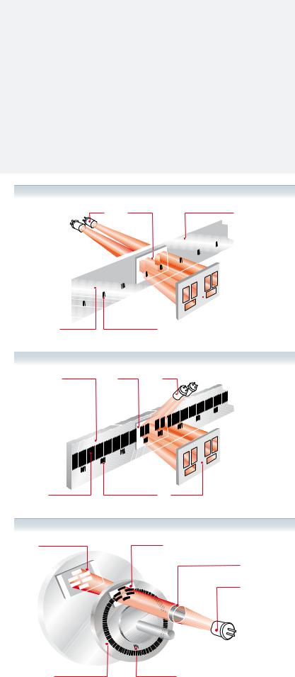
•Graduated glass: Linear encoders with a measuring length of up to 3 040 mm use optical transmission. The light from the LED goes through an engraved glass and a reticule before reaching the receiving photo diodes. The period of the generated electrical signals is the same as the graduation pitch.
•Graduated steel: Linear encoders with a measuring length over 3 040 mm use auto imaging principle which uses diffuse light reflected from the graduated steel tape. This optical reading system consists of a LED as a light source, a mesh that creates the image and a monolithic photo detector element in the image plane, which is specially designed and patented by Fagor.
Types of incremental encoders
•Linear encoder: Suitable for applications on milling, turning, boring mills, grinding machines for feedrates of up to 120 m/min and vibration levels up to 10 g.
•Rotary encoder: Used as measurement device for rotary axis, angular speed and also for linear movements for mechanisms like lead screws etc. They are widely used in machine tools, wood working equipment, robots and material handlers etc.
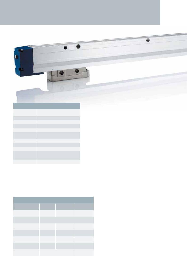
Enclosed design
The graduated scale in a linear encoder is protected by the enclosed aluminum profile. The highly durable sealing lips protect the encoder from industrial contaminants and liquid splashes as the reader head moves along the profile. The reader head movement in complete synchronization captures and transmits the position and movement of the machine. The reader head moves along the graduated scale on linear bearings minimizing the friction. For enhanced protection against contamination both ends of the encoder and also the reader head can be connected to pressurized air.
Graduated glass linear encoder
LED’s |
Grid |
Graduated glass |
|
|
|
|
|
|
|
|
|
|
|
|
|
|
|
|
|
|
|
|
|
|
|
|
|
|
|
|
|
|
|
|
|
|
|
|
|
|
|
|
|
|
|
|
|
|
|
|
|
|
|
|
|
|
|
|
|
|
|
|
|
|
|
|
|
|
Etching Reference marks |
Receiving photo-diodes |
||
Graduated steel linear encoder
Graduated steel |
Grid |
LED’s |
Etching |
Reference marks |
Receiving photo-diodes |
Graduated glass rotary encoder
Receiving photo-diodes |
Grid |
Flat convex lens
LED
Graduated glass disk |
Reference marks |
2
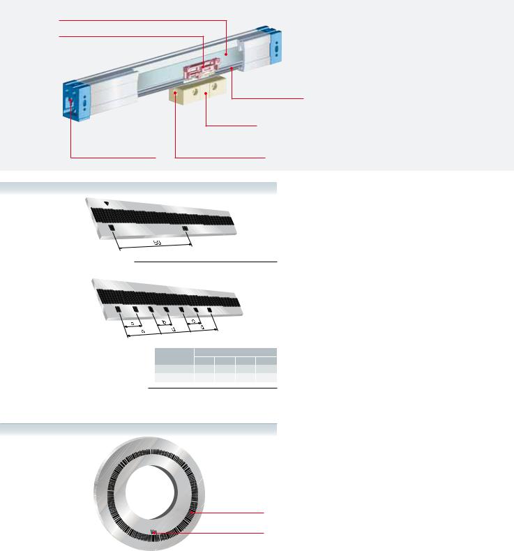
Graduated glass
Cursor
Sealing lips
Reader head
Air intake at both ends |
Air intake on the reader head |
|
|
|
|
Linear encoder
Incremental
|
|
Distances |
|
|
Series |
a |
b |
c |
d |
F |
50.1 |
50.2 |
50.3 |
100 |
C, M |
10.02 |
10.04 |
10.06 |
20 |
Distance-coded
Rotary encoder
Reference signals (I0)
The reference signal is a specially etched mark along the graduated glass, which when scanned generates a pulse signal. They are used to set/recover the machine zero position and avoid possible errors after powering up the DRO or CNC system.
Fagor provides two different types of reference marks I0:
•Incremental: The reference signal is synchronized with the feedback pulses to ensure perfect measuring repeatability.
Linear: One every 50 mm of travel.
Rotary: One signal per turn.
•Distance-coded: Each distance coded reference signal is separated from the next signal a different distance according to predefined mathematical function. The actual
position value after power up is restored by moving through two consecutive reference signals. This is very useful for long travel axes as the movement needed to recover actual position is minimum.
incremental I0
Pitch
Zero position
3
E N C O D E R S
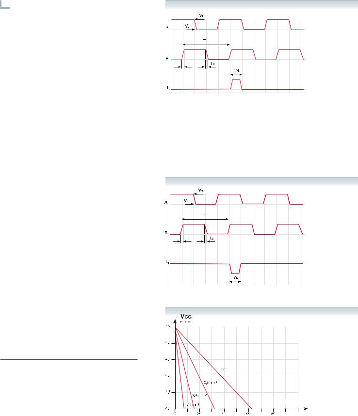
Electrical output signals

 Differential TTL
These are complementary signals in compliance with the EIA standard RS-422. This characteristic together with a line termination of 120 Ω, twisted pair, and an overall shield
provide greater immunity to electromagnetic noise caused by the surrounding environment.
Characteristics |
|
Signals |
A, /A, B, /B, I0, / I0 |
Signal level |
VH ≥ 2.5V IH= 20 mA |
|
VL ≤ 0.5V IL= 20 mA |
|
With 1 m cable |
90º reference signal (I0) |
Synchronized with A and B |
Switching time |
t+/t-< 30ns |
|
With 1 m cable |
|
|
T period |
according to model |
Max. cable length |
50 meters |
|
|
Load impedance |
Zo= 120 Ω between differential |


 No differential TTL
Characteristics |
|
|
|
Signals |
A, B, /I0 |
Signal level A, B, I0 |
VH ≥ 3.5 V IH = 4 mA |
|
VL ≤ 0.4 V IL = 4 mA |
|
with 1 m cable |
|
|
90º reference signal (I0) |
Synchronized with A and B |
Switching time |
t+/t-< 30ns |
|
with 1 m cable |
|
|
T period |
according to model |
Max. cable length |
20 meters |
Voltage drop across cable
The voltage requirements for a TTL encoder are 5V ±5%.
A simple formula described below, may be used to calculate the maximum cable length depending on the cross section diameter of the supply cable:
Lmax = (VCC-4,5)* 500 / (ZCABLE/Km* IMAX)
Example
Vcc = 5V, IMAX |
= |
0.2 |
Amp |
(with 120 Ω load) |
Z (1 mm2) |
= |
16.6 |
Ω/Km |
(Lmax= 75 m) |
Z (0.5 mm2) |
= |
32 |
Ω/Km |
(Lmax= 39 m) |
Z (0.25 mm2) |
= |
66 |
Ω/Km |
(Lmax= 19 m) |
Z (0.14 mm2) |
= |
132 |
Ω/Km |
(Lmax= 9 m) |
Cable length |
meters |
4
Cable length
meters
0.14mm2
0.09mm2
Cable length
meters
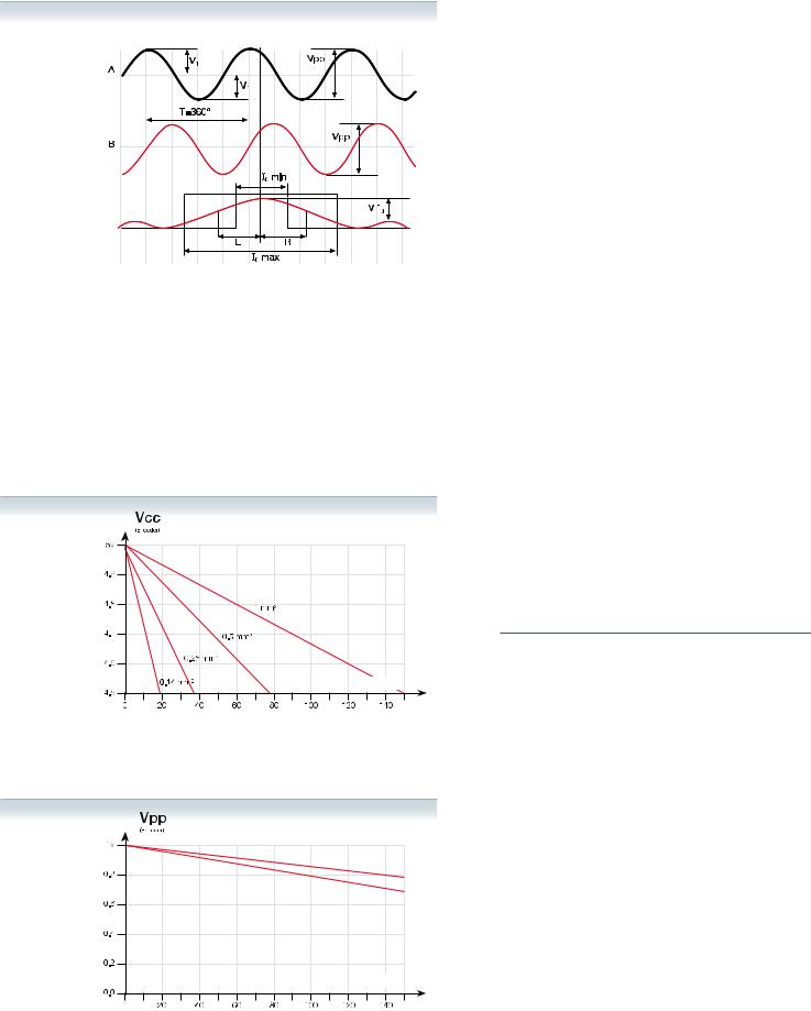
 Differential 1 Vpp
They are complementary sinusoidal signals whose differential value is 1 Vpp centered on Vcc/2. This characteristic together with a line termination of 120 Ω, twisted pair, and an overall shield provide greater immunity against electromagnetic noise caused by their surrounding environment.
Characteristics |
|
Signals |
A, /A, B, /B, I0, / I0 |
VApp |
1 V +20%, -40% |
|
|
VBpp |
1 V +20%, -40% |
DC offset |
2.5 V ± 0.5 V |
|
|
Signal period |
according to model |
Max. cable length |
150 meters |
A, B centered: |V1-V2| / 2 Vpp |
≤ 0.065 |
|
|
A&B relationship VApp / VBpp |
0.8 ÷ 1.25 |
A&B phase shift: |
90° ± 10° |
I0 amplitude: VI0 |
0.2 ÷ 0.8 V |
I0 width: L + R |
I0_min: 180° |
|
I0_typ: 360° |
|
I0_max: 540° |
I0 synchronism: L, R |
180º ± 90º |
Voltage drop across cable
The voltage requirements for a 1 Vpp encoder are 5V ±10%. A simple formula may be used to calculate the maximum cable length depending on the cross section diameter of the supply cables.
Lmax = (VCC-4,5)* 500 / (ZCABLE/Km* IMAX)
Example
Vcc |
= |
5V, IMAX= 0.1 Amp |
|
Z (1 mm2) |
= |
16.6 Ω/Km |
(Lmax= 150 m) |
Z (0.5 mm2) |
= |
32 Ω/Km |
(Lmax= 78 m) |
Z (0.25 mm2) |
= |
66 Ω/Km |
(Lmax= 37 m) |
Z (0.14 mm2) |
= |
132 Ω/ Km |
(Lmax= 18 m) |
1 Vpp signal damping due to the cable section
Besides attenuation due to signal frequency, there is another signal attenuation caused by the section of the cable connected to the encoder.
5
I N C R E M E N T A L
F series
L I N E A R
General specification
Measurement |
By means of stainless steel linear encoder |
|
|
with 100 μm etching pitch |
|
Steel tape accuracy |
± 5 µm |
|
Maximum speed |
120 m/min. |
|
Maximum vibration |
10 g |
|
Moving thrust |
< 5 N |
|
Operating |
0 ºC...50 ºC |
|
temperature |
||
|
||
Storage temperature |
-20 ºC...70 ºC |
|
Weight |
1.50 kg + 4 kg/m |
|
Relative humidity |
20...80% |
|
Protection |
IP 53 (standard) |
|
|
IP 64 (DIN 40050) using pressurized air in |
|
|
linear encoders at 0.8 ± 0.2 bar |
|
Reader head |
With detachable cable connector |
Especially designed for machines with longer travels and they are available up to 30 m in length. In the incremental model the reference marks are 50 mm apart and distance coded model is also available. Both models come with a detachable cable connectors in the reader head. The steel tape graduation pitch is 100 μm. For measuring lengths over 4040 mm the encoder is supplied in multiple sections and is assembled together at the time of installation.
Measuring lengths in millimeters
•Measuring lengths from 440 mm to 30 m in 200 mm increments. Contact Fagor Automation for custom length scales over 30 m.
Specific characteristics
Resolution
Reference marks (I0)
Output signals
T period of output signals
Limit frequency
Maximum cable length
Supply voltage
FT |
FX |
FP |
FOT |
FOX |
FOP |
5 µm |
1 µm |
Up to 0.1 µm |
FT, FX, FP: every 50 mm
FOT, FOX, FOP: Distance-coded I0
|
|
|
|
|
TTL |
|
|
|
|
|
TTL differential |
|
20 µm |
|
|
|
|
|
4 µm |
||||
100 kHz |
|
|
|
|
|
500 kHz |
|||||
|
20 m |
|
|
|
|
|
50 m |
||||
5 V ±5% ,100 mA (without load)
 1 Vpp
1 Vpp
100 µm
20 kHz
150 m
5 V ± 10%, < 100 mA (without load)
6
 Loading...