


Extron electronic SW6 SV MX AS, SW6 SA MX, SW6 CV MX AS, SW6 AV MX, SW6 AV MX AS User Manual
...User’s Manual
Audio/Video Switchers
|
|
|
|
|
|
|
|
|
SW6 AV MX |
|
|
|
|
|
|
|
|
|
SW6 AV MX AS |
|
|
|
|
|
|
|
|
|
SW6 CV MX |
|
|
|
|
|
|
|
|
|
SW6 CV MX AS |
|
|
|
|
|
|
|
|
|
SW6 SA MX |
|
|
|
|
|
|
|
|
|
SW6 SV MX |
|
|
|
|
|
|
|
|
|
SW6 SV MX AS |
|
|
|
|
|
|
|
|
|
SW6 SV A MX |
|
|
Extron Electronics, USA |
|
Extron Electronics, Europe |
|
Extron Electronics, Asia |
|
Extron Electronics, Japan |
SW6 SV A MX Auto |
|
|
|
|
|
|
||||
|
|
1230 South Lewis Street |
|
Beeldschermweg 6C |
|
135 Joo Seng Road, #04-01 |
|
Daisan DMJ Building 6F |
|
|
|
Anaheim, CA 92805 |
|
3821 AH Amersfoort |
|
PM Industrial Building |
|
3-9-1 Kudan Minami |
68-293-01 |
|
|
USA |
|
The Netherlands |
|
Singapore 368363 |
|
Chiyoda-ku, Tokyo 102-0074 Japan |
|
www.extron.com |
|
714.491.1500 |
|
+31.33.453.4040 |
|
+65.6383.4400 |
|
+81.3.3511.7655 |
Printed in the USA |
|
Fax 714.491.1517 |
|
Fax +31.33.453.4050 |
|
Fax +65.6383.4664 |
|
Fax +81.3.3511.7656 |
||
|
|
|
|
|
© 2002 Extron Electronics. All rights reserved.
Precautions
Safety Instructions • English |
Warning |
|
Thissymbolisintendedtoalerttheuserofimportant operating and maintenance (servicing) instructions in the literature provided with the equipment.
This symbol is intended to alert the user of the presence of uninsulated dangerous voltage within the product's enclosure that may present a risk of electric shock.
Caution
Read Instructions • Read and understand all safety and operating instructions before using the equipment.
Retain Instructions • The safety instructions should be kept for future reference.
Follow Warnings • Follow all warnings and instructions marked on the equipment or in the user information.
Avoid Attachments • Do not use tools or attachments that are not recommended by the equipment manufacturer because they may be hazardous.
Power sources • This equipment should be operated only from the power source indicated on the product. This equipment is intended to be used with a main power system with a grounded (neutral) conductor. The third (grounding) pin is a safety feature, do not attempt to bypass or disable it.
Power disconnection • To remove power from the equipment safely, remove all power cords from the rear of the equipment, or the desktop power module (if detachable), or from the power source receptacle (wall plug).
Power cord protection • Power cords should be routed so that they are not likely to be stepped on or pinched by items placed upon or against them.
Servicing • Refer all servicing to qualified service personnel. There are no userserviceable parts inside. To prevent the risk of shock, do not attempt to service this equipment yourself because opening or removing covers may expose you to dangerous voltage or other hazards.
Slots and openings • If the equipment has slots or holes in the enclosure, these are provided to prevent overheating of sensitive components inside. These openings must never be blocked by other objects.
Lithium battery • There is a danger of explosion if battery is incorrectly replaced. Replace it only with the same or equivalent type recommended by the manufacturer. Dispose of used batteries according to the manufacturer's instructions.
Consignes de Sécurité • Français
Ce symbole sert à avertir l’utilisateur que la documentation fournie avec le matériel contient des instructions importantes concernant l’exploitation et la maintenance (réparation).
Ce symbole sert à avertir l’utilisateur de la présence dansleboîtierdel’appareilde tensionsdangereuses non isolées posant des risques d’électrocution.
Attention
Lire les instructions• Prendre connaissance de toutes les consignes de sécurité et d’exploitation avant d’utiliser le matériel.
Conserver les instructions• Ranger les consignes de sécurité afin de pouvoir les consulter à l’avenir.
Respecter les avertissements • Observer tous les avertissements et consignes marqués sur le matériel ou présentés dans la documentation utilisateur.
Eviter les pièces de fixation • Ne pas utiliser de pièces de fixation ni d’outils non recommandés par le fabricant du matériel car cela risquerait de poser certains dangers.
Avertissement
Alimentations• Ne faire fonctionner ce matériel qu’avec la source d’alimentation indiquée sur l’appareil. Ce matériel doit être utilisé avec une alimentation principale comportant un fil de terre (neutre). Le troisième contact (de mise à la terre) constitue un dispositif de sécurité : n’essayez pas de la contourner ni de la désactiver.
Déconnexion de l’alimentation• Pour mettre le matériel hors tension sans danger, déconnectez tous les cordons d’alimentation de l’arrière de l’appareil ou du module d’alimentation de bureau (s’il est amovible) ou encore de la prise secteur.
Protection du cordon d’alimentation • Acheminer les cordons d’alimentation de manière à ce que personne ne risque de marcher dessus et à ce qu’ils ne soient pas écrasés ou pincés par des objets.
Réparation-maintenance • Faire exécuter toutes les interventions de réparationmaintenance par un technicien qualifié. Aucun des éléments internes ne peut être réparé par l’utilisateur. Afin d’éviter tout danger d’électrocution, l’utilisateur ne doit pas essayer de procéder lui-même à ces opérations car l’ouverture ou le retrait des couvercles risquent de l’exposer à de hautes tensions et autres dangers.
Fentes et orifices • Si le boîtier de l’appareil comporte des fentes ou des orifices, ceux-ci servent à empêcher les composants internes sensibles de surchauffer. Ces ouvertures ne doivent jamais être bloquées par des objets.
Lithium Batterie • Il a danger d'explosion s'll y a remplacment incorrect de la batterie. Remplacer uniquement avec une batterie du meme type ou d'un ype equivalent recommande par le constructeur. Mettre au reut les batteries usagees conformement aux instructions du fabricant.
Sicherheitsanleitungen • Deutsch
Dieses Symbol soll dem Benutzer in der im Lieferumfang enthaltenen Dokumentation besonders wichtige Hinweise zur Bedienung und Wartung (Instandhaltung) geben.
DiesesSymbolsolldenBenutzerdaraufaufmerksam machen, daß im Inneren des Gehäuses dieses ProduktesgefährlicheSpannungen,dienichtisoliert sind und die einen elektrischen Schock verursachen können, herrschen.
Achtung
Lesen der Anleitungen • Bevor Sie das Gerät zum ersten Mal verwenden, sollten Sie alle Sicherheits-und Bedienungsanleitungen genau durchlesen und verstehen.
Aufbewahren der Anleitungen • Die Hinweise zur elektrischen Sicherheit des Produktes sollten Sie aufbewahren, damit Sie im Bedarfsfall darauf zurückgreifen können.
Befolgen der Warnhinweise • Befolgen Sie alle Warnhinweise und Anleitungen auf dem Gerät oder in der Benutzerdokumentation.
Keine Zusatzgeräte • Verwenden Sie keine Werkzeuge oder Zusatzgeräte, die nicht ausdrücklich vom Hersteller empfohlen wurden, da diese eine Gefahrenquelle darstellen können.
Instrucciones de seguridad • Español
Este símbolo se utiliza para advertir al usuario sobre instrucciones importantes de operación y mantenimiento (o cambio de partes) que se desean destacar en el contenido de la documentación suministrada con los equipos.
Este símbolo se utiliza para advertir al usuario sobre la presencia de elementos con voltaje peligroso sin protección aislante, que puedan encontrarse dentro de la caja o alojamiento del producto, y que puedan representar riesgo de electrocución.
Precaucion
Leer las instrucciones • Leer y analizar todas las instrucciones de operación y seguridad, antes de usar el equipo.
Conservar las instrucciones • Conservar las instrucciones de seguridad para futura consulta.
Obedecer las advertencias • Todas las advertencias e instrucciones marcadas en el equipo o en la documentación del usuario, deben ser obedecidas.
Evitar el uso de accesorios • No usar herramientas o accesorios que no sean especificamente recomendados por el fabricante, ya que podrian implicar riesgos.
Vorsicht
Stromquellen • Dieses Gerät sollte nur über die auf dem Produkt angegebene Stromquelle betrieben werden. Dieses Gerät wurde für eine Verwendung mit einer Hauptstromleitung mit einem geerdeten (neutralen) Leiter konzipiert. Der dritte Kontakt ist für einen Erdanschluß, und stellt eine Sicherheitsfunktion dar. Diese sollte nicht umgangen oder außer Betrieb gesetzt werden.
Stromunterbrechung • Um das Gerät auf sichere Weise vom Netz zu trennen, sollten Sie alle Netzkabel aus der Rückseite des Gerätes, aus der externen Stomversorgung (falls dies möglich ist) oder aus der Wandsteckdose ziehen.
Schutz des Netzkabels • Netzkabel sollten stets so verlegt werden, daß sie nicht im Weg liegen und niemand darauf treten kann oder Objekte daraufoder unmittelbar dagegengestellt werden können.
Wartung • Alle Wartungsmaßnahmen sollten nur von qualifiziertem Servicepersonal durchgeführt werden. Die internen Komponenten des Gerätes sind wartungsfrei. Zur Vermeidung eines elektrischen Schocks versuchen Sie in keinem Fall, dieses Gerät selbst öffnen, da beim Entfernen der Abdeckungen die Gefahr eines elektrischen Schlags und/oder andere Gefahren bestehen.
Schlitze und Öffnungen • Wenn das Gerät Schlitze oder Löcher im Gehäuse aufweist, dienen diese zur Vermeidung einer Überhitzung der empfindlichen Teile im Inneren. Diese Öffnungen dürfen niemals von anderen Objekten blockiert werden.
Litium-Batterie • Explosionsgefahr, falls die Batterie nicht richtig ersetzt wird. Ersetzen Sie verbrauchte Batterien nur durch den gleichen oder einen vergleichbaren Batterietyp, der auch vom Hersteller empfohlen wird. Entsorgen Sie verbrauchte Batterien bitte gemäß den Herstelleranweisungen.
Advertencia
Alimentación eléctrica • Este equipo debe conectarse únicamente a la fuente/tipo de alimentación eléctrica indicada en el mismo. La alimentación eléctrica de este equipo debe provenir de un sistema de distribución general con conductor neutro a tierra. La tercera pata (puesta a tierra) es una medida de seguridad, no puentearia ni eliminaria.
Desconexión de alimentación eléctrica • Para desconectar con seguridad la acometida de alimentación eléctrica al equipo, desenchufar todos los cables de alimentación en el panel trasero del equipo, o desenchufar el módulo de alimentación (si fuera independiente), o desenchufar el cable del receptáculo de la pared.
Protección del cables de alimentación • Los cables de alimentación eléctrica se deben instalar en lugares donde no sean pisados ni apretados por objetos que se puedan apoyar sobre ellos.
Reparaciones/mantenimiento • Solicitar siempre los servicios técnicos de personal calificado. En el interior no hay partes a las que el usuario deba acceder. Para evitar riesgo de electrocución, no intentar personalmente la reparación/ mantenimiento de este equipo, ya que al abrir o extraer las tapas puede quedar expuesto a voltajes peligrosos u otros riesgos.
Ranuras y aberturas • Si el equipo posee ranuras o orificios en su caja/alojamiento, es para evitar el sobrecalientamiento de componentes internos sensibles. Estas aberturas nunca se deben obstruir con otros objetos.
Batería de litio • Existe riesgo de explosión si esta batería se coloca en la posición incorrecta. Cambiar esta batería únicamente con el mismo tipo (o su equivalente) recomendado por el fabricante. Desachar las baterías usadas siguiendo las instrucciones del fabricante.
Extron’s Warranty
Extron Electronics warrants this product against defects in materials and workmanship for a period of three years from the date of purchase. In the event of malfunction during the warranty period attributable directly to faulty workmanship and/or materials, Extron Electronics will, at its option, repair or replace said products or components, to whatever extent it shall deem necessary to restore said product to proper operating condition, provided that it is returned within the warranty period, with proof of purchase and description of malfunction to:
USA, Canada, |
Europe, Africa, and |
|
South America, and |
the Middle East: |
Asia: |
Central America: |
|
|
|
Extron Electronics, Europe |
Extron Electronics, Asia |
Extron Electronics |
Beeldschermweg 6C |
135 Joo Seng Road, #04-01 |
1230 South Lewis Street |
3821 AH Amersfoort |
PM Industrial Bldg. |
Anaheim, CA 92805, USA |
The Netherlands |
Singapore 368363 |
This Limited Warranty does not apply if the fault has been caused by misuse, improper handling care, electrical or mechanical abuse, abnormal operating conditions or non-Extron authorized modification to the product.
If it has been determined that the product is defective, please call Extron and ask for an Applications Engineer at (714) 491-1500 (USA), 31.33.453.4040 (Europe), or 65.383.4400
(Asia) to receive an RA# (Return Authorization number). This will begin the repair process as quickly as possible.
Units must be returned insured, with shipping charges prepaid. If not insured, you assume the risk of loss or damage during shipment. Returned units must include the serial number and a description of the problem, as well as the name of the person to contact in case there are any questions.
Extron Electronics makes no further warranties either expressed or implied with respect to the product and its quality, performance, merchantability, or fitness for any particular use. In no event will Extron Electronics be liable for direct, indirect, or consequential damages resulting from any defect in this product even if Extron Electronics has been advised of such damage.
Please note that laws vary from state to state and country to country, and that some provisions of this warranty may not apply to you.

Table of Contents
Chapter 1 • Introduction .......................................................... |
1-1 |
About the Audio and Video Switchers ...................... |
1-2 |
Features ...................................................................................... |
1-2 |
S-video models ....................................................................... |
1-3 |
Composite video models ....................................................... |
1-3 |
Audio models ......................................................................... |
1-3 |
Auto models ........................................................................... |
1-4 |
All models .............................................................................. |
1-4 |
Chapter 2 • Installation............................................................. |
2-1 |
Installation Overview .......................................................... |
2-2 |
Mounting the switcher ....................................................... |
2-2 |
Rear Panel Cabling ................................................................ |
2-3 |
Power connection .................................................................. |
2-3 |
Signal input connections ....................................................... |
2-3 |
S-video models ....................................................................... |
2-3 |
Composite video models ....................................................... |
2-3 |
Audio models ......................................................................... |
2-4 |
Signal output connections .................................................... |
2-5 |
S-video models ....................................................................... |
2-5 |
Composite video models ....................................................... |
2-5 |
Audio models ......................................................................... |
2-5 |
RS-232 or contact closure connection .................................. |
2-5 |
External sync connection....................................................... |
2-6 |
Chapter 3 • Operation ................................................................ |
3-1 |
Front Panel Controls and Indicators ............................ |
3-2 |
Front Panel Operations....................................................... |
3-3 |
Selecting an input.................................................................. |
3-4 |
Normal and auto-sync mode ................................................ |
3-4 |
Viewing the current switch mode ........................................ |
3-4 |
Selecting normal mode ......................................................... |
3-4 |
Selecting auto-sync mode ..................................................... |
3-4 |
Audio gain and attenuation ................................................. |
3-5 |
Viewing and adjusting an audio level .................................. |
3-6 |
Audio level reset .................................................................... |
3-6 |
Memory ...................................................................................... |
3-7 |
Troubleshooting — if no image appears ................... |
3-7 |
Audio/Video Switchers• Table of Contents |
i |

Table of Contents, cont’d
Chapter 4 • Remote Control .................................................. |
4-1 |
Simple Instruction Set Control ....................................... |
4-2 |
Host-to-interface communications ....................................... |
4-2 |
Switcher-initiated messages .................................................. |
4-3 |
Error responses ...................................................................... |
4-3 |
Timeout .................................................................................. |
4-3 |
Using the command/response table ..................................... |
4-4 |
Symbol definitions ................................................................. |
4-4 |
Command/response table for SIS commands ....................... |
4-5 |
Windows-Based Program Control ................................. |
4-6 |
Installing the software .......................................................... |
4-6 |
Using the software ................................................................ |
4-6 |
Using the help system ........................................................... |
4-7 |
Contact Closure Remote Control................................... |
4-7 |
Infrared Remote Control ................................................... |
4-8 |
Appendix A • Specifications ................................................. |
A-1 |
Accessories and Part Numbers |
|
Specifications ......................................................................... |
A-2 |
Included Parts ......................................................................... |
A-5 |
Accessories ............................................................................... |
A-5 |
Cables ......................................................................................... |
A-5 |
68-293-01 Rev. F
Printed in the USA
01 02
All trademarks mentioned in this manual are the properties of their respective owners.
 Audio/Video Switchers
Chapter1One
Introduction
About the Audio and Video Switchers
Features
ii Audio/Video Switchers • Table of Contents
Introductionroduction, cont’d
About the Audio and Video Switchers
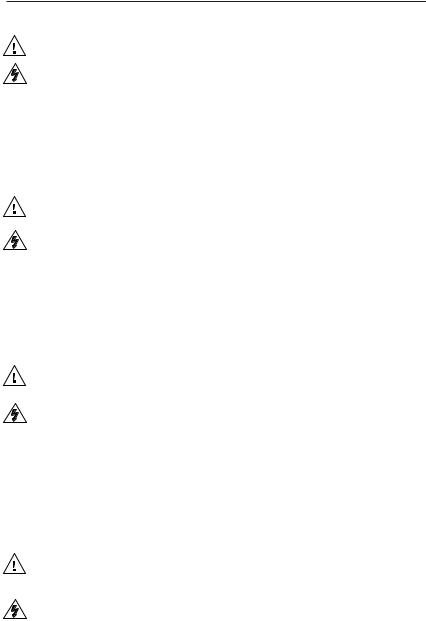
The Extron SW family of audio/video switchers are 6-input, 2-output composite video, S-video, and/or stereo audio switchers. The AS and Auto versions are functionally identical, but also include an auto-sync detect mode. Auto-sync detect mode, when enabled, automatically selects the highest numbered input with a video signal available. The following table identifies the models and their video, audio, and auto-sync capabilities.
A/V switchers’ attributes
Switcher
SW6 AV MX
SW6 AV MX AS
SW6 CV MX
SW6 CV MX AS
SW6 SA MX
SW6 SV MX
SW6 SV MX AS
SW6 SV A MX
SW6 SV A MX Auto
|
CompositeS |
c |
|
|
|
|
Auto |
|
|
|
- |
|
- |
|
syn |
|
video Audio detect |
||
Part # |
video |
||
|
|
|
|
60-208-01
60-208-22
60-205-01
60-205-22
60-206-01
60-207-01
60-207-22
60-358-01
60-358-02
The switchers are compatible with NTSC, PAL, and SECAM video. If external sync is connected, video switching occurs during the vertical interval, providing glitch-free switching.
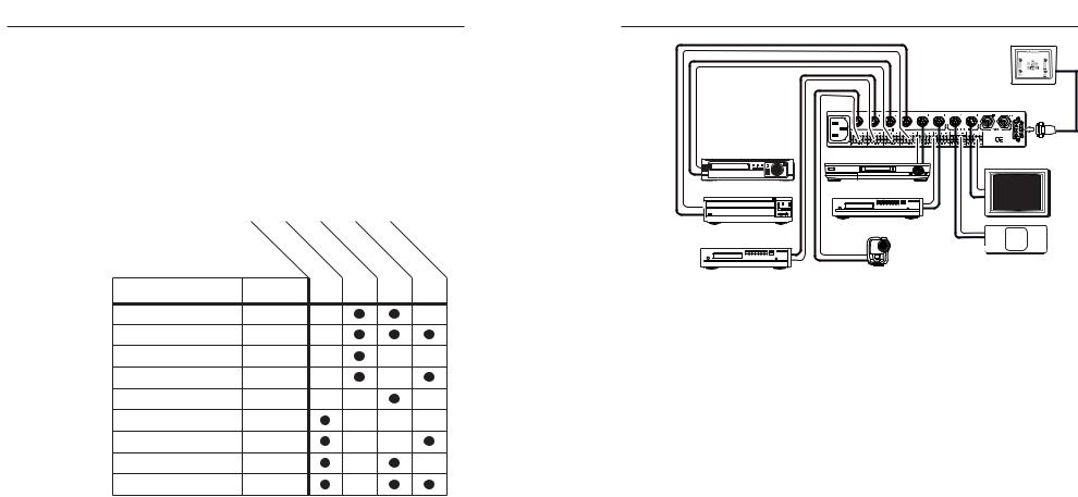
The switchers allow the user to switch between devices, such as a DSS receiver, a VHS or S-VHS VCR, a DVD player, or a camcorder and output the image to one or two video recorders or displays such as a data monitor or large screen projector (figure 1-1).
The ½-rack width switcher can be mounted to a standard Extron rack panel (part # 60-190-01). Each model has an internal 100VAC to 240VAC, 50/60 Hz, 10 watts, auto-switchable power supply that provides worldwide power compatibility.
|
RS-232 control |
|
SW 6 SV A MX |
100-240VAC 50/60Hz |
|
900 mA MAX |
REMOTE |
VCR |
DSS receiver |
MONITOR |
|
|
DVD player
Laserdisc player
LCD projector
DVD player |
Video camera |
Figure 1-1 — Typical A/V switcher application
Features
S-video models
Inputs — S-video switchers accept up to six S-video inputs on 4-pin mini DIN connectors.
Outputs — S-video switchers output two identical S-video signals on 4-pin mini DIN connectors.
Composite video models
Inputs — Composite video switchers accept up to six composite video inputs on BNC female connectors.
Outputs — Composite video switchers output two identical composite video signals on BNC female connectors.
Audio models
Inputs — Audio switchers accept up to six stereo audio inputs, balanced or unbalanced, on 3.5 mm, 5-pole captive screw terminals.
Outputs — Audio switchers output two identical stereo audio outputs, balanced or unbalanced, on 3.5 mm, 5-pole captive screw terminals.
Audio input gain and attenuation — Users can set the level of audio gain or attenuation (-15dB to +9dB) for each input via the RS-232 link or from the front panel. Individual input audio levels can be adjusted so there are no noticeable volume differences between sources.
1-2 |
Audio/Video Switchers • Introduction |
Audio/Video Switchers • Introduction |
1-3 |

Introduction, cont’d
Auto models
Auto-sync detect — Auto or AS models continuously monitor all inputs and automatically switch to the highestnumbered input with video sync pulses present. If video is absent from all inputs, no input is selected. The auto version can operate in either normal (manual switch) or auto-switch mode.
All models
Front panel control — The operator can select the input and set the audio gain and attenuation for each input using the front panel buttons.
RS-232 control — The operator can control the switcher from a remote computer or other host using an
RS-232 link on the Remote port. RS-232 control uses Extron’s Simple Instruction Set™ (SIS™) or the Windowsbased control software.
Simple Instruction Set — The Simple Instruction Set program lets a host computer control the switcher with simple commands.
Windows control software — Extron’s Windows-based control software provides a graphic way to set up and control the switcher with an on-screen control panel.
Contact closure — The operator can control the switcher remotely using a contact closure keypad connected to the Remote port.
Optional infrared remote control — The operator can also control the switcher using Extron’s IR 20 Universal SYS 4/8/10/AV remote control accessory (part #70-036-03) connected to the Remote port.
Rack mount option — The switchers are 1U high and a halfrack width wide. They can be installed on a standard rack shelf using an Extron 1U Shelf Rack, part # 60-190-01.
Auto-switching power supply — An internal power supply with an IEC connector makes power cord connection easy. The power supply can be used internationally with any power input from 110 VAC to 240 VAC at 50 or 60 Hz and adapts automatically to the input type.
 Audio/Video Switchers
Chapter2Two
Installation
Installation Overview
Mounting the switcher
Rear Panel Cabling
Audio/Video Switchers • Introduction

Installationtal ation, cont’d
Installation Overview
To install and set up an Extron A/V switcher for operation, follow these steps:
1Turn off all of the equipment that will be connected to the switcher.
2Mount the switcher. See Mounting the switcher in this chapter.
3Attach the cables. See Rear Panel Cabling in this chapter.
4Connect power cords and turn on the display devices and the input devices.
5Set the audio gain and attenuation. See Front Panel Controls and Indicators in chapter 3.
Mounting the switcher
1. For optional rack mounting, mount the A/V switcher on the left or right side of a 19" 1U Universal Rack Shelf (Extron part #60-190-01) (figure 2-1).
SW 6 SV A MX |
AUTO |
|
S-VIDEO AND |
|
|
|
AUDIO SWITCHER |
|
|
4-40 X 1/8 Screws |
|
|
|
Use 2 Mounting Holes |
False Front Panel |
|
|
on Opposite Corners |
Uses 2 Front Holes Only |
|
Figure 2-1 — Rack mounting the switcher |
|||
|
a. |
If feet were previously installed on the bottom of the |
|
|
|
case, remove them. |
|
|
b. |
Mount the switcher on the rack shelf, using two |
|
|
|
4-40 x 1/8 screws in opposite (diagonal) corners to |
|
|
|
secure the case to the shelf. |
|
2. |
If desired, attach a false front panel, or a second ½-rack- |
||
|
width device to the other side of the shelf. |
||
3. |
Attach the rack shelf to the rack using four 10-32 x ¾” bolts |
||
|
and four #10 beveled dress washers. |
||
Rear Panel Cabling
All connectors are on the rear panel. Depending on the model of the switcher, the type and layout of the connectors on the rear panel will vary. Figure 2-2 shows the rear panel of the
SW6 SV A MX switcher. Figure 2-3 shows the rear panel of the SW6 AV MX switcher. These two models have all the connectors available on the A/V switchers.
|
2 |
4 |
6 |
100-240VAC 50/60Hz |
|
|
|
900 mA MAX |
|
|
REMOTE |
1 |
3 |
5 |
7 |
Figure 2-2 — SW6 SV A MX rear panel cabling |
|||
|
2 |
4 |
6 |
100-240VAC 50/60Hz |
900 mA MAX |
REMOTE |
1 3 5 7
Figure 2-3 — SW6 AV MX rear panel cabling
Power connection
1AC power connector — Plug a standard IEC power cord into this connector to connect the switcher to a 100 to 240VAC, 50 Hz or 60 Hz power source.
Signal input connections
S-video models
2S-video input connectors — Connect S-video sources to these 4-pin mini DIN connectors.
Composite video models
2Composite video input connectors — Connect composite video sources to these female BNC connectors.
The A/V switchers do not alter the video signal in any way. The signal output from the switcher is in the same format as the input.
2-2 |
Audio/Video Switchers • Installation |
Audio/Video Switchers • Installation |
2-3 |
 Loading...