


 Loading...
PoleVault Systems
Installation Guide for the PVS 200, 300, and 400
68-1390-01
Rev. C
10 08

Precautions
Safety Instructions • English
This symbol is intended to alert the user of important operating and maintenance (servicing) instructions in the literature provided with the equipment.
This symbol is intended to alert the user of the presence of uninsulated dangerous voltage within the product’s enclosure that may present a risk of electric shock.
Caution
Read Instructions • Read and understand all safety and operating instructions before using the equipment. Retain Instructions • The safety instructions should be kept for future reference.
Follow Warnings • Follow all warnings and instructions marked on the equipment or in the user information.
Avoid Attachments • Do not use tools or attachments that are not recommended by the equipment manufacturer because they may be hazardous.
Consignes de Sécurité • Français
Ce symbole sert à avertir l’utilisateur que la documentation fournie avec le matériel contient des instructions importantes concernant l’exploitation et la maintenance (réparation).
Ce symbole sert à avertir l’utilisateur de la présence dans le boîtier de l’appareil de tensions dangereuses non isolées posant des risques d’électrocution.
Attention
Lire les instructions• Prendre connaissance de toutes les consignes de sécurité et d’exploitation avant d’utiliser le matériel.
Conserver les instructions• Ranger les consignes de sécurité afin de pouvoir les consulter à l’avenir.
Respecter les avertissements • Observer tous les avertissements et consignes marqués sur le matériel ou présentés dans la documentation utilisateur.
Eviter les pièces de fixation • Ne pas utiliser de pièces de fixation ni d’outils non recommandés par le fabricant du matériel car cela risquerait de poser certains dangers.
Sicherheitsanleitungen • Deutsch
Dieses Symbol soll dem Benutzer in der im Lieferumfang enthaltenen Dokumentation besonders wichtige Hinweise zur Bedienung und Wartung (Instandhaltung) geben.
Dieses Symbol soll den Benutzer darauf aufmerksam machen, daß im Inneren des Gehäuses dieses Produktes gefährliche Spannungen, die nicht isoliert sind und die einen elektrischen Schock verursachen können, herrschen.
Achtung
Lesen der Anleitungen • Bevor Sie das Gerät zum ersten Mal verwenden, sollten Sie alle Sicherheits-und Bedienungsanleitungen genau durchlesen und verstehen.
Aufbewahren der Anleitungen • Die Hinweise zur elektrischen Sicherheit des Produktes sollten Sie aufbewahren, damit Sie im Bedarfsfall darauf zurückgreifen können.
Befolgen der Warnhinweise • Befolgen Sie alle Warnhinweise und Anleitungen auf dem Gerät oder in der Benutzerdokumentation.
Keine Zusatzgeräte • Verwenden Sie keine Werkzeuge oder Zusatzgeräte, die nicht ausdrücklich vom Hersteller empfohlen wurden, da diese eine Gefahrenquelle darstellen können.
Instrucciones de seguridad • Español
Este símbolo se utiliza para advertir al usuario sobre instrucciones importantes de operación y mantenimiento (o cambio de partes) que se desean destacar en el contenido de la documentación suministrada con los equipos.
Este símbolo se utiliza para advertir al usuario sobre la presencia de elementos con voltaje peligroso sin protección aislante, que puedan encontrarse dentro de la caja o alojamiento del producto, y que puedan representar riesgo de electrocución.
Precaucion
Leer las instrucciones • Leer y analizar todas las instrucciones de operación y seguridad, antes de usar el equipo.
Conservar las instrucciones • Conservar las instrucciones de seguridad para futura consulta.
Obedecer las advertencias • Todas las advertencias e instrucciones marcadas en el equipo o en la documentación del usuario, deben ser obedecidas.
Evitar el uso de accesorios • No usar herramientas o accesorios que no sean especificamente recomendados por el fabricante, ya que podrian implicar riesgos.
•


••
••
Warning
Power sources • This equipment should be operated only from the power source indicated on the product. This equipment is intended to be used with a main power system with a grounded (neutral) conductor. The third (grounding) pin is a safety feature, do not attempt to bypass or disable it.
Power disconnection • To remove power from the equipment safely, remove all power cords from the rear of the equipment, or the desktop power module (if detachable), or from the power source receptacle (wall plug).
Power cord protection • Power cords should be routed so that they are not likely to be stepped on or pinched by items placed upon or against them.
Servicing • Refer all servicing to qualified service personnel. There are no user-serviceable parts inside. To prevent the risk of shock, do not attempt to service this equipment yourself because opening or removing covers may expose you to dangerous voltage or other hazards.
Slots and openings • If the equipment has slots or holes in the enclosure, these are provided to prevent overheating of sensitive components inside. These openings must never be blocked by other objects.
Lithium battery • There is a danger of explosion if battery is incorrectly replaced. Replace it only with the same or equivalent type recommended by the manufacturer. Dispose of used batteries according to the manufacturer’s instructions.
Avertissement
Alimentations• Ne faire fonctionner ce matériel qu’avec la source d’alimentation indiquée sur l’appareil. Ce matériel doit être utilisé avec une alimentation principale comportant un fil de terre (neutre). Le troisième contact (de mise à la terre) constitue un dispositif de sécurité : n’essayez pas de la contourner ni de la désactiver.
Déconnexion de l’alimentation• Pour mettre le matériel hors tension sans danger, déconnectez tous les cordons d’alimentation de l’arrière de l’appareil ou du module d’alimentation de bureau (s’il est amovible) ou encore de la prise secteur.
Protection du cordon d’alimentation • Acheminer les cordons d’alimentation de manière à ce que personne ne risque de marcher dessus et à ce qu’ils ne soient pas écrasés ou pincés par des objets.
Réparation-maintenance • Faire exécuter toutes les interventions de réparation-maintenance par un technicien qualifié. Aucun des éléments internes ne peut être réparé par l’utilisateur. Afin d’éviter tout danger d’électrocution, l’utilisateur ne doit pas essayer de procéder lui-même à ces opérations car l’ouverture ou le retrait des couvercles risquent de l’exposer à de hautes tensions et autres dangers.
Fentes et orifices • Si le boîtier de l’appareil comporte des fentes ou des orifices, ceux-ci servent à empêcher les composants internes sensibles de surchauffer. Ces ouvertures ne doivent jamais être bloquées par des objets.
Lithium Batterie • Il a danger d’explosion s’ll y a remplacment incorrect de la batterie. Remplacer uniquement avec une batterie du meme type ou d’un ype equivalent recommande par le constructeur. Mettre au reut les batteries usagees conformement aux instructions du fabricant.
Vorsicht
Stromquellen • Dieses Gerät sollte nur über die auf dem Produkt angegebene Stromquelle betrieben werden. Dieses Gerät wurde für eine Verwendung mit einer Hauptstromleitung mit einem geerdeten (neutralen) Leiter konzipiert. Der dritte Kontakt ist für einen Erdanschluß, und stellt eine Sicherheitsfunktion dar. Diese sollte nicht umgangen oder außer Betrieb gesetzt werden.
Stromunterbrechung • Um das Gerät auf sichere Weise vom Netz zu trennen, sollten Sie alle Netzkabel aus der Rückseite des Gerätes, aus der externen Stomversorgung (falls dies möglich ist) oder aus der Wandsteckdose ziehen.
Schutz des Netzkabels • Netzkabel sollten stets so verlegt werden, daß sie nicht im Weg liegen und niemand darauf treten kann oder Objekte daraufoder unmittelbar dagegengestellt werden können.
Wartung • Alle Wartungsmaßnahmen sollten nur von qualifiziertem Servicepersonal durchgeführt werden. Die internen Komponenten des Gerätes sind wartungsfrei. Zur Vermeidung eines elektrischen Schocks versuchen Sie in keinem Fall, dieses Gerät selbst öffnen, da beim Entfernen der Abdeckungen die Gefahr eines elektrischen Schlags und/oder andere Gefahren bestehen.
Schlitze und Öffnungen • Wenn das Gerät Schlitze oder Löcher im Gehäuse aufweist, dienen diese zur Vermeidung einer Überhitzung der empfindlichen Teile im Inneren. Diese Öffnungen dürfen niemals von anderen Objekten blockiert werden.
Litium-Batterie • Explosionsgefahr, falls die Batterie nicht richtig ersetzt wird. Ersetzen Sie verbrauchte Batterien nur durch den gleichen oder einen vergleichbaren Batterietyp, der auch vom Hersteller empfohlen wird. Entsorgen Sie verbrauchte Batterien bitte gemäß den Herstelleranweisungen.
Advertencia
Alimentación eléctrica • Este equipo debe conectarse únicamente a la fuente/tipo de alimentación eléctrica indicada en el mismo. La alimentación eléctrica de este equipo debe provenir de un sistema de distribución general con conductor neutro a tierra. La tercera pata (puesta a tierra) es una medida de seguridad, no puentearia ni eliminaria.
Desconexión de alimentación eléctrica • Para desconectar con seguridad la acometida de alimentación eléctrica al equipo, desenchufar todos los cables de alimentación en el panel trasero del equipo, o desenchufar el módulo de alimentación (si fuera independiente), o desenchufar el cable del receptáculo de la pared.
Protección del cables de alimentación • Los cables de alimentación eléctrica se deben instalar en lugares donde no sean pisados ni apretados por objetos que se puedan apoyar sobre ellos.
Reparaciones/mantenimiento • Solicitar siempre los servicios técnicos de personal calificado. En el interior no hay partes a las que el usuario deba acceder. Para evitar riesgo de electrocución, no intentar personalmente la reparación/mantenimiento de este equipo, ya que al abrir o extraer las tapas puede quedar expuesto a voltajes peligrosos u otros riesgos.
Ranuras y aberturas • Si el equipo posee ranuras o orificios en su caja/alojamiento, es para evitar el sobrecalientamiento de componentes internos sensibles. Estas aberturas nunca se deben obstruir con otros objetos.
Batería de litio • Existe riesgo de explosión si esta batería se coloca en la posición incorrecta. Cambiar esta batería únicamente con el mismo tipo (o su equivalente) recomendado por el fabricante. Desachar las baterías usadas siguiendo las instrucciones del fabricante.
•
•
•
•
•
•
Introduction
FCC Class A Notice
This equipment has been tested and found to comply with the limits for a Class A digital device, pursuant to part 15 of the FCC Rules. Operation is subject to the following
two conditions: (1) this device may not cause harmful interference, and (2) this device must accept any interference received, including interference that may cause undesired operation. The Class A limits are designed to provide reasonable protection against harmful interference when the equipment is operated in a commercial environment. This equipment generates, uses, and can radiate radio frequency energy and, if not installed and used in accordance with the instruction manual, may cause harmful interference to radio communications. Operation of this equipment in a residential area is likely to cause harmful interference, in which case the user will be required to correct the interference at his own expense.
Overview
This manual covers the installation of the Extron PoleVault™ System in a drop ceiling room with a wood or concrete structural ceiling. If the location has a concrete or beam style ceiling, alternative ceiling mounts can be obtained separately from Extron (see 2c, "Optional items", later in this chapter). For those types of installation, refer to the individual mounting hardware user's manuals for method.
It is assumed that the installer has some knowledge and experience of A/V, electrical, or electronic device installation. This manual guides the A/V installer through the steps for installation and connection of each of the system’s component parts.
It may be that the locations for the devices (e.g., wall plates, projector, and screen) have been pre-determined.
However, some room installation examples are given to help in installations where final location is yet to be determined.
The PoleVault System
Extron PoleVault Systems are easy-to-use, network-enabled, all-inclusive packages, making them ideal for singleprojector K-12 classrooms. PoleVault Systems use economical twisted pair cables for transmitting signals and include network connectivity for Web-based asset management, monitoring, and control.
NThe hardware and devices listed on the inventory pages have individual user manuals which have detailed safety information, installation, set-up, and configuration instructions, and should be referred to as needed.
For operation and set up of the projector, screen, and input devices, refer to the relevant manufacturer's manuals supplied with those devices.
PoleVault Systems Installation • Introduction |
1-1 |
Introduction, cont'd
4
Audio
Video In
IN
AUDIO
 IN
IN
COMPUTER |
1 (x2)
PVT RGB D
1 Gang
RGB and Audio Input
Video In
|
DIO |
IN |
|
AU |
|
L |
|
|
|
||
|
|
|
R |
|
|
IN |
1 |
VIDEO |
|
|
|
PVT CV D
1 Gang
Video and Audio Input
Video In
PCM 240 |
4 |
Projector Drop Ceiling
Mount
Audio |
Ceiling Mounted |
PV SI 3C LP |
|
AC Outlet |
|
|
|
Full Range |
|
|
Single Driver |
|
|
Ceiling Speakers |
7 PoleVault
8 for Projector
PMK 450
Multi-product Pole
 Mount Kit
PVS 204SA
PoleVault Switcher
IN
AUDIO
|
IN |
|
COMPUTER |
1 |
(x2) |
|
PVT RGB D
1 Gang
RGB and Audio Input
3
 2
2
Communication
Video Out |
PMP 6 |
RS-232 |
Projector Mounting Pole |
|
UPB 25 |
|
Universal Projector |
5 |
Mounting Bracket |
6
|
OFF |
|
ON |
|
|
VOLUME |
|
|
|
|
Comm Adapter |
|
MLC 104 IP Plus |
(depending on |
|
projector type) |
|
|
Projector on/off control |
|
|
|
|
9 |
Projector input switching |
|
Projector volume control |
|
|
|
|
|
|
2 Gang (depth: 1.78”) |
|
TCP/IP |
Extron PoleVault™ System |
|
|
Network |
|
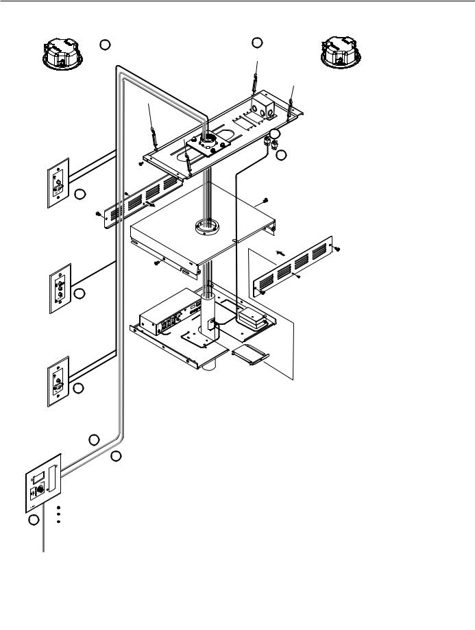
PoleVault System installation and wiring overview
Extron Cables & Notes
1CAT 5 T568A cable - 50'
2Projector control cable - 50'
3MLC power and control cable - 50'
418 AWG Speaker cable - 25'
5Composite Video cable - 3'
6VGA Video cable - 3'
7PoleVault Switcher power cable - 25'
8Projector power cord - not included
9UTP network cable - not included
1-2 PoleVault Systems Installation • Introduction
Before you Begin Installation - Planning
Before installation is started, several major factors must be considered to ensure that the overall installation is as smooth and trouble free as possible, and that the final finished project meets the needs of the customers, users, audiences, and installer.
The installation consideration on the following pages, though not comprehensive, should be consulted to help ensure that key aspects have been considered.
1.Room layout
a.The room
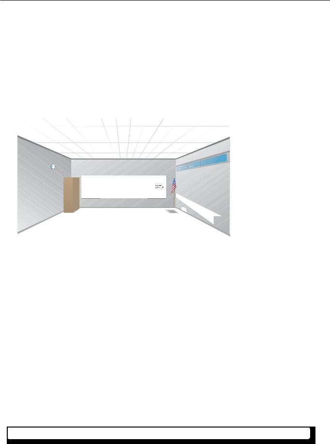
The application diagram below shows a typical classroom installation.
Typical classroom installation
Room factors to be considered should include, but are not confined to:
•Room size, orientation, and layout:
Audience factors (e.g. number, ADA requirements, seating arrangements)
Existing installed furniture (bookcases, racks, cabinets, workbenches, sinks, etc.)
Windows, doors, and support pillar locations in relationship to the proposed screen location
•Ceiling and wall type (important in assessing the installation hardware needed)
Ceiling type: dropped, spline, hard lid etc., structural type (wood, concrete, trusses), plenum or non-plenum
Wall type: drywall, cement, brick etc.
W Check the structural ceiling to ensure that it can handle a load four times the weight of the final setup.
PoleVault Systems Installation • Introduction — Planning |
1-3 |
Introduction — Planning, cont’d
•Lighting
Type and control (important for projector image viewing)
Ambient light from windows
Windows
TV / VCR / DVD
Inputs
Student Desks
Speaker
Location
Projector/Switcher
Location
|
MLC Controller |
|
Location |
|
Teacher’s Desk |
PVT A/V Wallplate |
Screen/White Board |
Location |
Location |
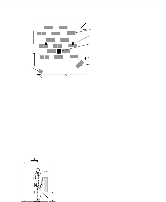
Example classroom installation
b.Location of the screen and projector
•Proposed screen location
Normally located at the front center of the room (not covering fire alarm strobes when screen is lowered)
Dimensions and type of screen (maximum image size, motorized or hanging screen)
•Proposed projector location
Aligned with center of the screen. Not an obstruction to viewing
Projector's throw distance (maximum and minimum limits to screen) of the image
Horizontal offset (horizontal distance from the center of the lens to the center of the projector)
Vertical offset of the projected image (height relationship between the projector and the screen)
Projector angle (image projected up, down, or horizontal to screen)
Power source for the projector: existing and accessible or needing installation
Projector weight. The Universal Projector Bracket (UPB 25) supports a maximum weight of 25 lbs.
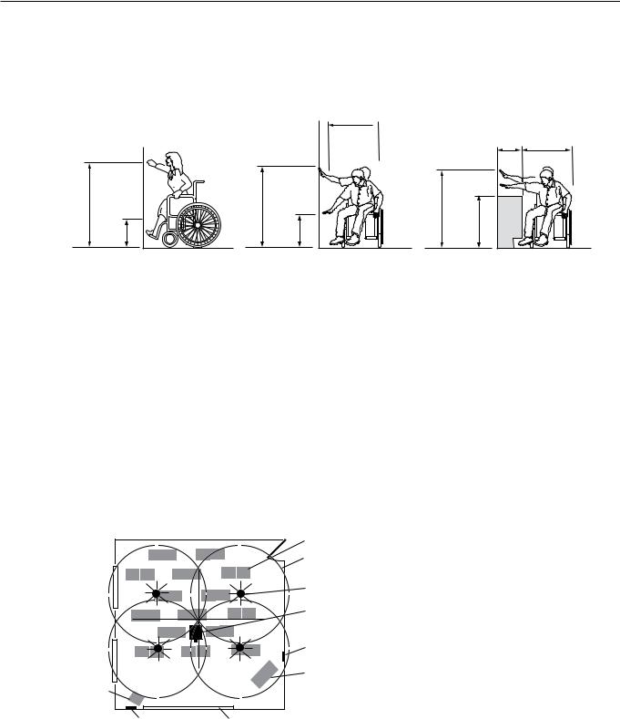
Overhead clearances (refer to a copy of "ADA Standards for Accessible Design", "Section 4-4", "Head Room" for ADA requirements)
4" (10 cm)
Max
80" (203 cm) Min
Greater than 27"
(68.5 cm)
Walking Parallel to a Wall (ADA referenced figure 8a, redrawn)
ADA overhead and side clearance requirements
1-4 PoleVault Systems Installation • Introduction — Planning
•Viewing obstructions
Pillars, furniture etc., window locations for glare reduction, obstructions between projector and screen c. Location of MediaLink Controller and Wall Plates
•Forward and side reach (for full details refer to a copy of "ADA Standards for Accessible Design", "Section 4-2",
"Space Allowance and Reach Ranges")
10"
(25.5 cm)  Max
Max
48" |
54" |
(122 cm) |
(137 cm) |
Max |
Max |
15" |
9" |
(38 cm) |
(23 cm) |
Min |
Min |
30"
 (76 cm)
|
24" |
30" |
|
(61 cm) |
(76 cm) |
46" |
|
|
(117 cm) |
34" |
|
Max |
|
|
(86.5 cm) |
|
|
|
|
High Forward Reach Limits |
High / Low Side Reach Limits |
Max Side Reach over Obstruction Limits |
(ADA referenced figure 5a, redrawn) |
(ADA referenced figure 6b, redrawn) |
(ADA referenced figure 6c, redrawn) |
ADA high/low forward, side and over obstruction reach limit requirements
•Location of source devices
Desk, table, or rack mounted, proximity to proposed transmitter location (wall, podium, or furniture)
•Cabling obstacles
Studs, utility pipes, power supply location (raceway installation needed?)
•Network drop for MediaLink Controller
Wall or floor cabled
d. Type and location of the speakers
•Speaker type based on room ceiling and wall type
•Total number and spacing of speakers
Based on ceiling height and room size
•Audience seating and room acoustics
Desired evenness of sound coverage and ambient noise level compensation
Student Desks
Each speaker covers one-fourth of listening area.
Windows |
Speaker |
|
Location |
||
|
Projector/Switcher
Location
MLC Controller
Location
TV / VCR / DVD
Inputs
Teacher’s |
Desk |
PVT A/V Wallplate |
Screen/White board |
Location |
Location |
Example classroom with four speaker installation
PoleVault Systems Installation • Introduction — Planning |
1-5 |

Introduction — Inventory Overview
2.Inventory
a.Included items
The PoleVault System (PVS xxx) ships in two boxes. The larger box (42-1xx-xx) contain the devices and hardware, individually boxed and labeled. The smaller box (42-103-13) contains only the PV SI 3C LP speakers. Each PVS system has the same quantities of speakers, hardware and devices, but differ in the number and type of PoleVault A/V Source Input Wall Plates, and are shipped as follows:
•PVS 200 (part # 42-108-03) includes one PVT RGB D and one PVT CV D
•PVS 300 (part # 42-109-03) includes two PVT RGB D and one PVT CV D
•PVS 400 (part # 42-110-03) includes two PVT RGB D and two PVT CV D (see front cover of this manual)
Carefully check all the received items against the following lists.
PoleVault System Devices and Hardware
PoleVault System
42-108-03 (or 42-109-03, or 42-110-03*)
PCM 240 |
UPB 25 |
PMK 450 |
|
|
UPB 25 White |
PMP |
CABLES |
PCM 240 White |
PMK 450 White |
|
|
60-772-03 |
60-773-03 |
70-618-03 |
|
|
|
PMP 6 White |
(1) SPK 18, 25’ |
|
|
70-511-13 |
|
|
|
|
|
|
|
|
(1) MVGA M-M, 3’ |
PCM 240 |
UPB 25 |
PMK 450 |
|
Projector Ceiling Mount |
Universal Projector Bracket |
Pole Mount Kit |
|
|
|
PMP |
|
|
|
Projector |
(1) V RCA, 3’ |
|
|
Mounting Pole |
|
|
|
|
|
|
|
(1) MLC, PW/RS232/VC, 50’ |
|
|
|
(4) M6 x 40 mm screws |
(7) Replacement screws |
|
(4)Turnbuckles |
(4) M5 x 40 mm screws |
(2) Velcro™ pads |
||
(4) M4 x 40 mm screws |
(1) Set screw Hex wrench |
|||
(5) |
Lag eyes screws |
|||
(4) M3 x 40 mm screws |
(1) Security screw Hex wrench |
|||
(5) |
Concrete anchors |
|||
0.328 ID washers (4) |
|
|||
(2) |
Cable clamps, Gal Steel |
|
||
#10 washers (4) |
|
|||
(1) |
Safety wire (15 ft 1/8” dia) |
|
||
#6 washers (4) |
|
|||
(2) Tie wire (30 ft, 14 AWG) |
|
|||
Adhesive pads (4) |
|
|||
(4) |
Locking Screws |
|
||
Hex key (1) |
|
|||
(4) |
Adhesive pads |
|
||
|
|
|||
(1) |
Hex key |
|
|
|
(1) IR SERIAL COMM, 50’
CAT5 T568A Patch, 50’
Quantity varies depending on PVS system ordered.
These may be boxed separately or loose inside larger box.
1-6 PoleVault Systems Installation • Introduction — Inventory Overview

PoleVault System Devices and Hardware, (cont'd)
PoleVault System Devices and Hardware, cont’d
PoleVault System
42-108-03 (or 42-109-03, or 42-110-03*)
PVT CV D |
PVT RGB D |
MLC 104 IP Plus |
PVS 204SA |
PVT CV D White
60-819-13
PVT CV D
Wallplate
(1)Mud ring
(2)Dog legs
(2) Dog leg screws
(2) PVT mounting screws
(1)Decora® Faceplate
(2)Faceplate screws
PVT RGB D White
60-820-13
PVT RGB D
Wallplate
(1)Mud ring
(2)Dog legs
(2) Dog leg screws
(2) PVT mounting screws
(1)Decora® Faceplate
(2)Faceplate screws
*Part #’s 42-109-03 and 42-110-03
contain 3 or 4 PoleVault Wallplates, according to type ordered.
MLC 104 IP Plus White
60-818-03
MLC 104 IP Plus
MediaLink Controller
(1) Mud ring
(8) Mud ring screws
(8) Replacement screws
PVS 204SA 60-800-01
PVS 204SA
PoleVault Switcher
(1)2-pole connector (orange)
(2)3-pole connector (blue)
(1)5-pole connector (blue)
(1)Audio connector (black)
(2)Securing screws
(4)Tie wraps
(4)Adhesive foot pads
(2)Velcro® pads
(1) Power supply
(1) Power cord
PoleVault Systems Installation • Introduction — Inventory Overview |
1-7 |
Introduction — Inventory Overview, cont’d
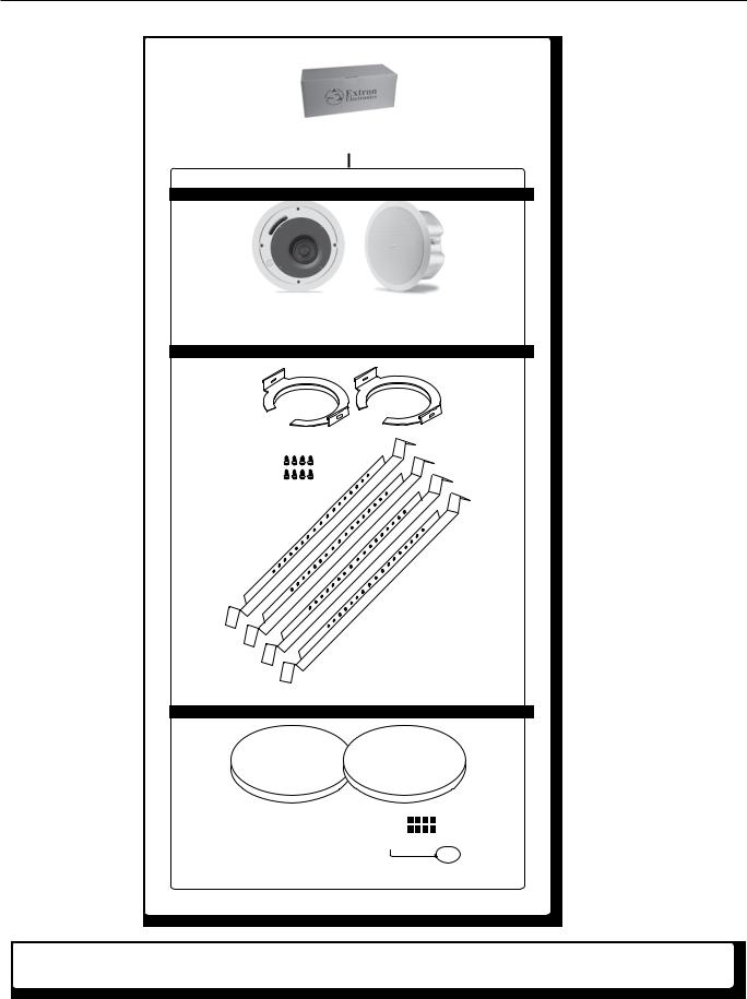
PoleVault System Ceiling Speakers
PV SI 3C LP White
42-103-13
PV SI 3C LP
PV SI 3C LP
Speakers
(2) C-rings
(8) C-ring attaching screws
(4) V-rails
(2) Speaker grills (8 pcs) Grill putty
(1) Grill key
NIf any items in the PoleVault System boxes are damaged or missing, contact the Extron Technical Hotline (see rear cover for contact numbers).
1-8 PoleVault Systems Installation • Introduction — Inventory Overview
b. Items not included
The following items are not included. However, input and display devices are essential parts of the system, and at any installation they may vary depending on their use. This list suggests various devices that may be used.
•Projector (or display device)
•Screen (and mounting hardware)
•Input devices, such as:
DVD/CD/VCR combo player (and cables)
Document camera (and cables)
PC or Mac (with keyboard, mouse, local monitor, VGA cables, RJ-45 network cables, power cords, and, where desired, a P/2 DA2 or DA for PC signal to local monitor and projector)
•Installation hardware needed (may vary per installation):
Bolts for concrete structural ceilings where needed
Toggles (used for screen mounting on dry wall)
S-hooks for hanging the screen
Spare ceiling tiles in case of accidental damage during installation
Electrical box, where installation of a box on the PCM 240 is desired
Safety wire, lag eye bolts, and strain reliefs for installation and securing ceiling speakers
Heat shrink, extension cord c. Optional items
The optional items suggested below can be added to or substituted for items in the standard PoleVault System.
•Optional accessories:
MLP 101 D (mic to line pre-amplifier)
Wall mount speakers (e.g., SI 26) or extra ceiling speakers
MLC 104 IP Plus DV+ controller (includes DVD/VCR IR control)
MLC 104 IP Plus L controller (with lectern faceplate)
MLC 104 IP Plus AAP controller (with AAP opening)
PPC 25 Priority Page Controller
P/2 DA2
•Optional installation hardware:
FCMP (flat ceiling mount)
ACMP (angled ceiling mount)
SMB (surface mount boxes for installing the MLC on a podium or desk)
EWB (external wall boxes to mount devices for a surface raceway system)
MLM-WB+ (lockable metal wall box with flip-down 4U rack space)
•Optional A/V source inputs:
PVT CV AAP (composite video architectural adapter plate model)
PVT RGB AAP (RGB architectural adapter plate model)
PVT RGB (RGB rack mount model)
PVT SW RGB (RGB rack mount model with switching capabilities)
PVT CV (composite video rack mount model)
PVT RGB CV (RGB and composite video rack mount model)
•Optional speakers:
SI 3 (Compact Full-Range Surface Mount Speakers)
SI 26X (Two-Way Open Back Ceiling Speakers)
SI 26W (Two-Way-In-Wall Speakers with 6.5" Woofer)
SI 28W (Two-Way-In-Wall Speakers with 8" Woofer)
SI 26CT (Two-Way Ceiling Speakers with 8" Back Can and Transformer)
SI 26 (Two-Way Surface Mount Speakers with 6.5" Woofer)
PoleVault Systems Installation • Introduction — Inventory Overview |
1-9 |

Introduction — Inventory Overview, cont’d
d. Installation tools
To aid the professional installer, this checklist gives the tools recommended to complete the installation. Tools should include, but are not confined to:
•Laser level, or two levels (large for screen installation, small for wall plates and projector mounts)
•Tape measure
•Stud finder
•Drill and drill bit set including a Unibit to cut through metal studs
•Extension drill bit (3/4" min., 4 to 8 foot length, to drill through fire-breaks)
•Socket set
•Pipe strap or wrapped pipe wrench
•Lineman’s pliers and wire strippers
•Standard screwdriver set and Tweeker
•Cable cutters (to cut safety wire)
•Dry wall saw and hacksaw blade mounted on handle (for cutting ceiling tiles)
•Flashlight and safety goggles
•Razor knife
•2" hole saw
•Painter's tape (to mark up walls), pencil, and marker pen
•RJ-45 crimpers and RJ-45 connectors
•Voltage tester
•Fish tape, pull string, and electrical tape (for taping fish tape to pull string)
•Zip ties
•Vacuum cleaner
•Heat gun
1-10 PoleVault Systems Installation • Introduction — Inventory Overview
Installation Overview
This overview outlines the basic steps for installing the PoleVault System. Detailed description of these steps is given in five sections, Stages One though Five.
NAdditional installation hardware is needed and should be supplied by the installer. See Introduction, “Items not included”, for a list.
Optional accessories may be desired for this installation. See Introduction, “Optional items”, for a list, or visit www.extron.com for details.
Refer to local building standards and codes to verify that the installation will meet all the regulatory requirements. Observe all local and national building and safety codes, UL requirements, and ADA Accessibility Guidelines.
For details of the OSHPD approved method of installation (OPA-1782), consult the PCM 240 User’s Manual, 68-1180-01, Rev D.
Refer to the specifications on pages 2-31 through 2-33 for system hardware weights and dimensions.
Carefully check inventory of PoleVault system packages, input and output devices, any optional accessories, and installation hardware before commencing.
Outline of installation steps
Stage One — Install the Screen and Projector.
cMark the screen location (page 2-3).
cInstall projector to verify location (page 2-3).
cVerify the image location (page 2-4).
cCut the ceiling tile (page 2-5).
cFinish projector ceiling mount installation (page 2-5).
cSecure the projector ceiling mount to the ceiling (page 2-6).
cInstall the screen (page 2-7).
Stage Two — Install the A/V Source Input Wall Plates and MLC 104 IP Plus.
cInstall the mud rings (page 2-10).
cPull cables (page 2-11).
cInstall the wall plates (page 2-12).
cInstall the MediaLink Controller (page 2-13).
Stage Three — Install the PV SI 3C LP Ceiling Speakers.
cCut the ceiling tile (page 2-17).
cInstall the speaker in the ceiling tile (page 2-17).
cSecure the speakers to the structural ceiling (page 2-18).
cCable the speakers (page 2-18).
cFinish speaker installation (page 2-20).
Stage Four — Install the PMK 450 and the PVS 204SA.
cPull the cables (page 2-22).
cInstall the PMK 450 pole mount kit (page 2-22).
cInstall the PVS 204SA switcher (page 2-23).
cFinish installing the pole mount kit (page 2-24).
Stage Five — Configuring the system.
cConfigure the system (page 2-26).
cTest the system (page 2-28).
cFinal installation (page 2-29).
Where possible in the following pages, line drawings and photos from an actual installation are used to clarify some of the steps discussed in the text. Each image has a number corresponding to the particular step (e.g., Ñ) described.
PoleVault Systems Installation • Installation Overview |
2-1 |
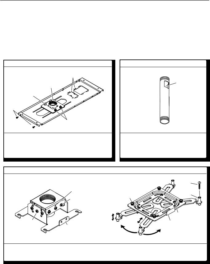
Stage OneStage— Ins all the Screen and Projector1
This stage involves installing the three pieces of hardware shown below.
PCM 240 Projector Ceiling Mount
1-gang and 2-gang Accessory Mounting Points (e.g. power sockets)
Pipe
Pipe Adapter
Adapter
Set Screws (2)
T-bar
Securing
Screws (4)
Pipe Adapter Plate
Lock Nuts (4)
Where it goes: Attaches to structural ceiling, rests on suspended ceiling.
What it does: Holds PMP, Pole Mount Kit (see Stage 4), and projector.
PMP Projector Mounting Pole
|
Cable |
|
|
Access |
|
Threaded at both |
Cutout |
|
(install this |
||
ends |
||
end uppermost) |
||
|
Where it goes: Screws up into PCM 240.
What it does: Holds Pole Mount Kit and projector.
UPB 25 Universal Projector Bracket (shown separated into the two sections)
Adjuster Plate
(Top Section)
Vertical Angle
Adjustment
Screws (4) 
Pivot
Point
Screw
Set Screws (2)
Horizontal Angle
Adjustment Screws (4)
 Pivot Point screws (4)
Security Flange (on rear)
Projector Bracket |
Projector Securing |
|
(Bottom Section) |
||
Screw |
Threaded
Adjuster Plate Barrels (4)
Locking Screws (4)
 Arm Adjustment
Screws (4)
Security Flange (on rear)
360° Movement
Where it goes: Adjuster plate screws onto base of PMP, and projector bracket attaches to projector. What it does: Attaches projector to PMP. Allows projector orientation to be adjusted in three planes.
2-2 PoleVault Systems Installation • Installation — Stage 1
Loading...