


 Loading...
Extron electronic MTPX PLUS 128, MTPX PLUS 816, MTPX PLUS 1632, MTPX PLUS 3216, MTPX PLUS 3232 User Manual
...Setup Guide
|
|
|
|
|
|
|
|
|
|
|
|
|
MTPX Plus Series |
|
|
|
|
|
|
|
|
|
|
|
|
|
Mini Twisted Pair Matrix Switchers |
Extron USA - West |
|
Extron USA - East |
|
Extron Europe |
|
Extron Asia |
|
Extron Japan |
|
Extron China |
|
Extron Middle East |
|
|
|
|
|
|
|
|
|||||||
Headquarters |
|
+800.633.9876 |
|
+800.3987.6673 |
|
+800.7339.8766 |
|
+81.3.3511.7655 |
|
+400.883.1568 |
|
+971.4.2991800 |
68-1560-01 Rev. B |
|
|
|
|
|
|
|
|||||||
+800.633.9876 |
|
Inside USA / Canada Only |
|
Inside Europe Only |
|
Inside Asia Only |
|
+81.3.3511.7656 FAX |
|
Inside China Only |
|
+971.4.2991880 FAX |
03 10 |
Inside USA / Canada Only |
|
+1.919.863.1794 |
|
+31.33.453.4040 |
|
+65.6383.4400 |
|
|
|
+86.21.3760.1568 |
|
|
|
|
|
|
|
|
|
|
|
|
|
||||
+1.714.491.1500 |
|
+1.919.863.1797 FAX |
|
+31.33.453.4050 FAX |
|
+65.6383.4664 FAX |
|
|
|
+86.21.3760.1566 FAX |
|
|
|
+1.714.491.1517 FAX |
|
|
|
|
|
|
|
|
|
|
|
|
|
© 2010 Extron Electronics. All rights reserved.
Precautions
Safety Instructions • English
Thissymbolisintendedtoalerttheuserofimportant operatingandmaintenance(servicing)instructionsin the literature provided with the equipment.
This symbol is intended to alert the user of the presence of uninsulated dangerous voltage within the product’s enclosure that may present a risk of electric shock.
Caution
Read Instructions • Read and understand all safety and operating instructions before using the equipment.
Retain Instructions • The safety instructions should be kept for future reference.
Follow Warnings • Follow all warnings and instructions marked on the equipment or in the user information.
Avoid Attachments • Do not use tools or attachments that are not recommended by the equipment manufacturer because they may be hazardous.
Warning
Power sources • This equipment should be operated only from the power source indicated on the product. This equipment is intended to be used with a main power system with a grounded (neutral) conductor. The third (grounding) pin is a safety feature, do not attempt to bypass or disable it.
Power disconnection • To remove power from the equipment safely, remove all power cords from the rear of the equipment, or the desktop power module (if detachable), or from the power source receptacle (wall plug).
Power cord protection • Power cords should be routed so that they are not likely to be stepped on or pinched by items placed upon or against them.
Servicing • Refer all servicing to qualified service personnel. There are no userserviceable parts inside. To prevent the risk of shock, do not attempt to service this equipment yourself because opening or removing covers may expose you to dangerous voltage or other hazards.
Slots and openings • If the equipment has slots or holes in the enclosure, these are provided to prevent overheating of sensitive components inside. These openings must never be blocked by other objects.
Lithium battery • There is a danger of explosion if battery is incorrectly replaced. Replace it only with the same or equivalent type recommended by the manufacturer. Dispose of used batteries according to the manufacturer’s instructions.
Consignes de Sécurité • Français
Ce symbole sert à avertir l’utilisateur que la documentation fournie avec le matériel contient des instructionsimportantesconcernantl’exploitationet la maintenance (réparation).
Ce symbole sert à avertir l’utilisateur de la présence dansleboîtierdel’appareilde tensionsdangereuses non isolées posant des risques d’électrocution.
Attention
Lire les instructions• Prendre connaissance de toutes les consignes de sécurité et d’exploitation avant d’utiliser le matériel.
Conserver les instructions• Ranger les consignes de sécurité afin de pouvoir les consulter à l’avenir.
Respecter les avertissements • Observer tous les avertissements et consignes marqués sur le matériel ou présentés dans la documentation utilisateur.
Eviter les pièces de fixation • Ne pas utiliser de pièces de fixation ni d’outils non recommandés par le fabricant du matériel car cela risquerait de poser certains dangers.
Avertissement
Alimentations• Ne faire fonctionner ce matériel qu’avec la source d’alimentation indiquée sur l’appareil. Ce matériel doit être utilisé avec une alimentation principale comportant un fil de terre (neutre). Le troisième contact (de mise à la terre) constitue un dispositif de sécurité : n’essayez pas de la contourner ni de la désactiver.
Déconnexion de l’alimentation• Pour mettre le matériel hors tension sans danger, déconnectez tous les cordons d’alimentation de l’arrière de l’appareil ou du module d’alimentation de bureau (s’il est amovible) ou encore de la prise secteur.
Protection du cordon d’alimentation • Acheminer les cordons d’alimentation de manière à ce que personne ne risque de marcher dessus et à ce qu’ils ne soient pas écrasés ou pincés par des objets.
Réparation-maintenance • Faire exécuter toutes les interventions de réparationmaintenance par un technicien qualifié. Aucun des éléments internes ne peut être réparé par l’utilisateur. Afin d’éviter tout danger d’électrocution, l’utilisateur ne doit pas essayer de procéder lui-même à ces opérations car l’ouverture ou le retrait des couvercles risquent de l’exposer à de hautes tensions et autres dangers.
Fentes et orifices • Si le boîtier de l’appareil comporte des fentes ou des orifices, ceux-ci servent à empêcher les composants internes sensibles de surchauffer. Ces ouvertures ne doivent jamais être bloquées par des objets.
Lithium Batterie • Il a danger d’explosion s’ll y a remplacment incorrect de la batterie. Remplacer uniquement avec une batterie du meme type ou d’un ype equivalent recommande par le constructeur. Mettre au reut les batteries usagees conformement aux instructions du fabricant.
Sicherheitsanleitungen • Deutsch
Dieses Symbol soll dem Benutzer in der im Lieferumfang enthaltenen Dokumentation besonders wichtige Hinweise zur Bedienung und Wartung (Instandhaltung) geben.
DiesesSymbolsolldenBenutzerdaraufaufmerksam machen, daß im Inneren des Gehäuses dieses ProduktesgefährlicheSpannungen,dienichtisoliert sind und die einen elektrischen Schock verursachen können, herrschen.
Achtung
Lesen der Anleitungen • Bevor Sie das Gerät zum ersten Mal verwenden, sollten Sie alle Sicherheits-und Bedienungsanleitungen genau durchlesen und verstehen.
Aufbewahren der Anleitungen • Die Hinweise zur elektrischen Sicherheit des Produktes sollten Sie aufbewahren, damit Sie im Bedarfsfall darauf zurückgreifen können.
Befolgen der Warnhinweise • Befolgen Sie alle Warnhinweise und Anleitungen auf dem Gerät oder in der Benutzerdokumentation.
Keine Zusatzgeräte • Verwenden Sie keine Werkzeuge oder Zusatzgeräte, die nicht ausdrücklich vom Hersteller empfohlen wurden, da diese eine Gefahrenquelle darstellen können.
Instrucciones de seguridad • Español
Este símbolo se utiliza para advertir al usuario sobre instrucciones importantes de operación y mantenimiento (o cambio de partes) que se desean destacar en el contenido de la documentación suministrada con los equipos.
Este símbolo se utiliza para advertir al usuario sobre la presencia de elementos con voltaje peligroso sin protección aislante, que puedan encontrarse dentro de la caja o alojamiento del producto, y que puedan representar riesgo de electrocución.
Precaucion
Leer las instrucciones • Leer y analizar todas las instrucciones de operación y seguridad, antes de usar el equipo.
Conservar las instrucciones • Conservar las instrucciones de seguridad para futura consulta.
Obedecer las advertencias • Todas las advertencias e instrucciones marcadas en el equipo o en la documentación del usuario, deben ser obedecidas.
Evitar el uso de accesorios • No usar herramientas o accesorios que no sean especificamente recomendados por el fabricante, ya que podrian implicar riesgos.
Vorsicht
Stromquellen • Dieses Gerät sollte nur über die auf dem Produkt angegebene Stromquelle betrieben werden. Dieses Gerät wurde für eine Verwendung mit einer Hauptstromleitung mit einem geerdeten (neutralen) Leiter konzipiert. Der dritte Kontakt ist für einen Erdanschluß, und stellt eine Sicherheitsfunktion dar. Diese sollte nicht umgangen oder außer Betrieb gesetzt werden.
Stromunterbrechung • Um das Gerät auf sichere Weise vom Netz zu trennen, sollten Sie alle Netzkabel aus der Rückseite des Gerätes, aus der externen Stomversorgung (falls dies möglich ist) oder aus der Wandsteckdose ziehen.
Schutz des Netzkabels • Netzkabel sollten stets so verlegt werden, daß sie nicht im Weg liegen und niemand darauf treten kann oder Objekte daraufoder unmittelbar dagegengestellt werden können.
Wartung • Alle Wartungsmaßnahmen sollten nur von qualifiziertem Servicepersonal durchgeführt werden. Die internen Komponenten des Gerätes sind wartungsfrei. Zur Vermeidung eines elektrischen Schocks versuchen Sie in keinem Fall, dieses Gerät selbst öffnen, da beim Entfernen der Abdeckungen die Gefahr eines elektrischen Schlags und/oder andere Gefahren bestehen.
Schlitze und Öffnungen • Wenn das Gerät Schlitze oder Löcher im Gehäuse aufweist, dienen diese zur Vermeidung einer Überhitzung der empfindlichen Teile im Inneren. Diese Öffnungen dürfen niemals von anderen Objekten blockiert werden.
Litium-Batterie • Explosionsgefahr, falls die Batterie nicht richtig ersetzt wird. Ersetzen Sie verbrauchte Batterien nur durch den gleichen oder einen
vergleichbaren Batterietyp, der auch vom Hersteller empfohlen wird. Entsorgen Sie verbrauchte Batterien bitte gemäß den Herstelleranweisungen.
Advertencia
Alimentación eléctrica • Este equipo debe conectarse únicamente a la fuente/tipo de alimentación eléctrica indicada en el mismo. La alimentación eléctrica de este equipo debe provenir de un sistema de distribución general con conductor neutro
a tierra. La tercera pata (puesta a tierra) es una medida de seguridad, no puentearia ni eliminaria.
Desconexión de alimentación eléctrica • Para desconectar con seguridad la acometida de alimentación eléctrica al equipo, desenchufar todos los cables de alimentación en el panel trasero del equipo, o desenchufar el módulo de alimentación (si fuera independiente), o desenchufar el cable del receptáculo de la pared.
Protección del cables de alimentación • Los cables de alimentación eléctrica se deben instalar en lugares donde no sean pisados ni apretados por objetos que se puedan apoyar sobre ellos.
Reparaciones/mantenimiento • Solicitar siempre los servicios técnicos de personal calificado. En el interior no hay partes a las que el usuario deba acceder. Para evitar riesgo de electrocución, no intentar personalmente la reparación/mantenimiento de este equipo, ya que al abrir o extraer las tapas puede quedar expuesto a voltajes peligrosos u otros riesgos.
Ranuras y aberturas • Si el equipo posee ranuras o orificios en su caja/alojamiento, es para evitar el sobrecalientamiento de componentes internos sensibles. Estas aberturas nunca se deben obstruir con otros objetos.
Batería de litio • Existe riesgo de explosión si esta batería se coloca en la posición incorrecta. Cambiar esta batería únicamente con el mismo tipo (o su equivalente) recomendado por el fabricante. Desachar las baterías usadas siguiendo las instrucciones del fabricante.
Extron Warranty
Extron Electronics warrants this product against defects in materials and workmanship for a period of three years from the date of purchase. In the event of malfunction during the warranty period attributable directly to faulty workmanship and/or materials, Extron Electronics will, at its option, repair or replace said products or components,
to whatever extent it shall deem necessary to restore said product to proper operating condition, provided that it is returned within the warranty period, with proof of purchase and description of malfunction to:
USA, Canada, South America, |
Europe, Africa, and the Middle East: |
and Central America: |
Extron Electronics, Europe |
|
|
Extron Electronics |
Beeldschermweg 6C |
1001 East Ball Road |
3821 AH Amersfoort |
Anaheim, CA 92805, USA |
The Netherlands |
Asia: |
Japan: |
Extron Electronics, Asia |
Extron Electronics, Japan |
135 Joo Seng Road, #04-01 |
Kyodo Building |
PM Industrial Bldg. |
16 Ichibancho |
Singapore 368363 |
Chiyoda-ku, Tokyo 102-0082 |
|
Japan |
This Limited Warranty does not apply if the fault has been caused by misuse, improper handling care, electrical or mechanical abuse, abnormal operating conditions or nonExtron authorized modification to the product.
If it has been determined that the product is defective, please call Extron and ask for an Applications Engineer at (714) 491-1500 (USA), 31.33.453.4040 (Europe), 65.6383.4400 (Asia), or 81.3.3511.7655 (Japan) to receive an RA# (Return Authorization number). This will begin the repair process as quickly as possible.
Units must be returned insured, with shipping charges prepaid. If not insured, you assume the risk of loss or damage during shipment. Returned units must include the serial number and a description of the problem, as well as the name of the person to contact in case there are any questions.
Extron Electronics makes no further warranties either expressed or implied with respect to the product and its quality, performance, merchantability, or fitness for any particular use. In no event will Extron Electronics be liable for direct, indirect, or consequential damages resulting from any defect in this product even if Extron Electronics has been advised of such damage.
Please note that laws vary from state to state and country to country, and that some provisions of this warranty may not apply to you.
•
有重要的操作和维护说明。

•
•
•
•
•
•
••
•
•
FCC Class A Notice
This equipment has been tested and found to comply with the limits for a Class A digital device, pursuant to part 15 of the FCC Rules. Front Panel Operation is subject to the following two conditions: (1) this device may not cause harmful interference, and (2) this device must accept any interference received, including interference that may cause undesired operation. The Class A limits are designed to provide reasonable protection against harmful interference when the equipment
is operated in a commercial environment. This equipment generates, uses, and can radiate radio frequency energy and, if not installed and used in accordance with the instruction manual, may cause harmful interference to radio communications. Front Panel Operation of this equipment in a residential area is likely to cause harmful interference, in which case the user will be required to correct the interference at his own expense.
NThis unit was tested with shielded cables on the peripheral devices. Shielded cables must be used with the unit to ensure compliance with FCC emissions limits.

Table of Contents
Chapter One • Introduction ................................................... |
1-1 |
About this Manual ..................................................................... |
1-2 |
About the MTPX Pl us Switchers............................................ |
1-2 |
Twisted Pair (TP) Cabl e Transmission Distance................. |
1-4 |
TP Skew Equal ization................................................................ |
1-5 |
Chapter Two • Installation....................................................... |
2-1 |
Rear Panel ..................................................................................... |
2-2 |
Inputs....................................................................................... |
2-3 |
RS-232 output inserts............................................................. |
2-4 |
Outputs................................................................................... |
2-4 |
Remote control ....................................................................... |
2-5 |
Power...................................................................................... |
2-6 |
Front Panel .................................................................................... |
2-6 |
Chapter Three • Front Panel Operation.......................... |
3-1 |
Creating a Tie............................................................................... |
3-2 |
Saving or Recalll ing a Preset.................................................... |
3-3 |
Setting the Front Panel Locks (Executive Modes\........... |
3-4 |
Sel ecting Lock mode 2 or toggl ing between |
|
mode 2 and mode 0 ................................................................ |
3-4 |
Sel ecting Lock mode 2 or toggl ing between |
|
mode 2 and mode 1 ................................................................ |
3-5 |
Defining the Audio/RS-232 Wire Pair |
|
and Configuring the Remote Port.......................................... |
3-6 |
Viewing and Adjusting the Audio Level ............................ |
3-7 |
Viewing Ties and Muting Outputs....................................... |
3-8 |
Video Adjustments.................................................................... |
3-8 |
Chapter Four • Remote Control and |
|
Optimizing the Video................................................................... |
4-1 |
Sel ected SIS™ Commands......................................................... |
4-2 |
Establ ishing a network (Ethernet) connection..................... |
4-2 |
Connection timeouts............................................................... |
4-2 |
Number of connections.......................................................... |
4-3 |
Verbose mode.......................................................................... |
4-3 |
Establ ishing a USB port connection...................................... |
4-3 |
Host-to-switcher instructions................................................ |
4-3 |
Command/response tabl e for sel ected SIS commands........ |
4-4 |
MTPX Pl us Series • Tabl e of Contents |
i |
Refer also to the MTPX Plus User’s Manual at www.extron.com.

Table of Contents, cont’d
Installl ing and Starting the Control Program................... |
4-15 |
Installl ing the program......................................................... |
4-15 |
First-time connection considerations.................................. |
4-16 |
LAN port connection............................................................. |
4-16 |
USB port connection............................................................. |
4-16 |
Starting the program........................................................... |
4-17 |
Optimizing the video........................................................... |
4-18 |
Setting the MTP transmitter Pre-Peak feature.................... |
4-19 |
Setting MTPX l evel and peaking using the MTP signal |
|
generator............................................................................... |
4-19 |
Manualll y setting the MTPX l evel and peaking................... |
4-20 |
Setting MTPX skew............................................................... |
4-20 |
Sel ecting MTPX Pl us Pre-Peak.............................................. |
4-22 |
Setting MTP Receiver l evel /peaking.................................... |
4-22 |
Accessing the HTML Pages.................................................... |
4-23 |
Configuring for Network Communication.......................... |
4-24 |
Loading the start-up page................................................... |
4-25 |
All trademarks mentioned in this manual are the properties of their respective owners.
ii MTPX Pl us Series • Tabl e of Contents

 MTPX Pl us Series Matrix Switcher
Chapter1One
Introduction
About this Manual
About the MTPX Plus Switchers
Twisted Pair (TP) Cable Transmission Distance
TP Skew Equalization
Refer also to the MTPX Plus User’s Manual at www.extron.com.
Introduction
About this Manual
This setup guide allows you to easily and quickly set up and configure your Extron MTPX Plus Twisted Pair (TP) Matrix Switcher. Step by step instructions show you how to connect the hardware and then use the physical controls, Simple Instruction Set (SIS™) commands, the Matrix Switchers Control Program, and built-in HTML pages to optimize the video and audio output for the best quality.
About the MTPX Plus Switchers
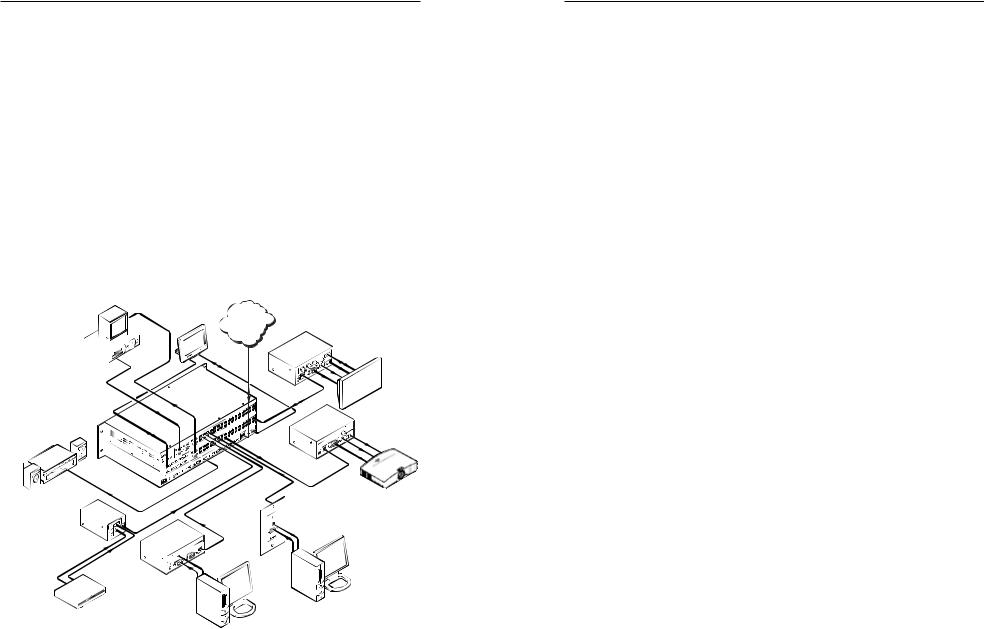
The MTPX Plus matrix switcher (figure 1-1) distributes signals that are compatible with the Extron MTP and VTT/VTR product lines. The matrix switcher routes a TP input signal to any combination of TP outputs. Depending on the MTP model,
the routed TP signal can include RGB or low resolution video and either mono audio or transmitter-to-receiver RS-232 serial communications. The matrix switcher can route multiple input/output configurations simultaneously.
Monitor |
Control |
|
Extron |
|
MTP U R RSA SEQ |
||
|
System |
TCP/IP |
|
Rack |
|
Network |
Universal Receiver |
|
|
Plasma / LCD |
|
Mounted |
|
|
|
|
|
Display |
|
PC |
|
|
|
|
|
|
Extron |
|
|
MTPX Plus 3232 |
Extron |
|
Twisted Pair |
||
MTP U R A |
||
Matrix |
||
Universal |
||
Switcher |
||
Receiver |
||
Sound System |
LCD projector |
|
Extron |
||
|
||
Extron |
MTP T 15HD A D |
|
Transmitter |
||
MTP T SV A |
|
|
Transmitter |
|
|
Extron |
|
|
MTP T 15HD A |
|
|
Transmitter |
PC |
|
DVD |
||
|
||
|
PC |
Figure 1-1 — Typical MTPX Plus application
NThe receiver-to-transmitter serial communications and remote power capabilities available with certain MTP models are not supported by this matrix switcher.
1-2 MTPX Pl us Series • Introduction
The switchers are available in the following matrix sizes:
•MTPX Plus 816 (8 inputs by 16 outputs)
•MTPX Plus 128 (12 inputs by 8 outputs)
•MTPX Plus 168 (16 inputs by 8 outputs)
•MTPX Plus 1616 (16 inputs by 16 outputs)
•MTPX Plus 1632 (16 inputs by 32 outputs)
•MTPX Plus 3216 (32 inputs by 16 outputs)
•MTPX Plus 3232 (32 inputs by 32 outputs)
The switchers input and output TP signals on RJ-45 connectors.
NFor best results, use a cable length of at least 50 feet (15 m) between the TP inputs and outputs and the transmitter and receiver.
Three, four, or six (depending on the matrix size) 15-pin HD and 5-pole 3.5 mm direct insertion input connectors are available for direct RGB (VGA) and stereo audio inputs without an MTP transmitter.
NFor most switchers, the available local inputs parallel the TP input of the same number and either input can be used.
For the MTPX Plus 128, four inputs are local only and eight inputs are TP only.
Two, four, or eight (depending on the matrix size) 5-pole 3.5 mm captive screw ports are available for direct mono audio outputs to an audio device without an MTP transmitter.
One or two (depending on the matrix size) 15-pin HD output connectors are available for direct RGB (VGA) output to a video device without an MTP receiver.
NThe direct input and direct output connectors can also support HD-YUV video, YUV video, S-video, and composite video.
NFor low resolution MTPs (S-video and composite video) on the TP inputs and outputs, the MTPX Plus audio circuits are compatible only with the newer generation, mono audio models. See the MTP transmitter/receiver manual to determine which MTP models you have.
There are 4, 8, or 16 (depending on the matrix size) 3-pole 3.5 mm captive screw ports for bidirectional RS-232 signal
inserts. These signals, from a dedicated source (rather than from the selected input), can be directly inserted into the signal set routed to the TP output.
The matrix switcher can be remotely controlled via an Ethernet LAN port, serial port, or USB port (MTPX Plus 128 only) connection using either the Windows®-based Extron Matrix Switchers Control Program or the Simple Instruction Set (SIS).
MTPX Pl us Series • Introduction |
1-3 |
Refer also to the MTPX Plus User’s Manual at www.extron.com. |
Refer also to the MTPX Plus User’s Manual at www.extron.com. |

Introduction, cont’d
Twisted Pair (TP) Cable Transmission Distance
CDo not connect this device to a computer data or telecommunications network.
The maximum distance is determined by the frequency and resolution of the signal that is input to the transmitter or to one of the local inputs of the matrix switcher. The table below specifies the recommended maximum transmission distances using Extron Enhanced Skew-Free™ A/V UTP cable or UTP CAT 5, 5e, or 6 cable, terminated with RJ-45 connectors.
Recommended transmission distances at 60 Hz
|
High quality transmission |
Variable quality transmission |
||||
Video |
maximum distance |
maximum distance |
||||
format |
MTPX input |
|
MTPX output |
MTPX input |
|
MTPX output |
|
|
|||||
Composite, |
700 feet |
|
700 feet |
750 feet |
|
750 feet |
S-video, |
(215 m) |
|
(215 m) |
(230 m) |
|
(230 m) |
Component |
|
|
|
|
|
|
640 x 480 |
550 feet |
|
600 feet |
600 feet |
|
650 feet |
(165 m) |
|
(185 m) |
(185 m) |
|
(200 m) |
|
|
|
|
||||
800 x 600 |
500 feet |
|
500 feet |
600 feet |
|
600 feet |
(150 m) |
|
(150 m) |
(185 m) |
|
(185 m) |
|
|
|
|
||||
1024 x 768 |
450 feet |
|
450 feet |
550 feet |
|
550 feet |
(135 m) |
|
(135 m) |
(168 m) |
|
(168 m) |
|
|
|
|
||||
1280 x 1024 |
350 feet |
|
350 feet |
450 feet |
|
450 feet |
(100 m) |
|
(100 m) |
(135 m) |
|
(135 m) |
|
|
|
|
||||
1600 x 1200 |
300 feet |
|
300 feet |
450 feet |
|
450 feet |
(90 m) |
|
(90 m) |
(135 m) |
|
(135 m) |
|
|
|
|
||||
For any transmission distances beyond 350 feet (100 m), turn on the pre-peak function on the transmitting device (MTP transmitter or MTPX Plus) . See the MTP Transmitter/Receiver User’s Manual and/or the "Output pre-peaking SIS commands" on page 4-8.
NThe minimum TP cable length should be 25 feet (7.6 m).
NIt is possible to exceed the recommended distance; however, image quality may be reduced.
NThe transmitters, receivers, and matrix switcher are designed for and perform best with Extron Enhanced Skew-Free A/V cable terminated in accordance with the TIA/EIA T 568 A wiring standard. CAT 5, 5e, and 6 cables are acceptable, but less preferable. Extron also recommends the use of preterminated and tested cables. Cables terminated on site should be tested before use to ensure that they comply with Category 5 specifications.
1-4 MTPX Pl us Series • Introduction
NThe recommendations shown on the preceding page apply equally for a transmission line consisting of a single transmitter, the switcher, and a receiver; and for a transmission line that encompasses a transmission
daisy chain. For example, the maximum suggested range for 1024 x 768 video output by the switcher is 550 feet (168 m) with Pre-Peak on whether the transmission line consists of the transmitter, switcher, and a single receiver or a transmitter, the switcher, and three daisy-chained receivers.
NFor daisy-chained units, the first receiver in the chain should be at least 50 feet (15 m) from the switcher when the Pre-Peak feature is on.
NFor daisy-chained units, any receiver in the chain closer than 350 feet (105 m) may experience some form of overpeaking when the Pre-Peak switch is on.
TP Skew Equalization
Skew exists between wire pairs when the physical length of one wire pair is different from another. Skew affects the displayed image when the difference in length between wire pairs exceeds 2 feet. The difference in length causes the timing of the red, green, and blue video signals to appear out of alignment (horizontal registration errors). The signals transmitted on the shortest pair are shifted to the left if you are using white lines on a black background. A white vertical line on a black field can appear as individual red, green, and blue lines that are close together; the signal transmitted on the shortest wire pair leads the other colors and appears to the left on the display. As the transmission cable length increases, the skew effect increases.
The MTPX Plus input and output skew equalizer functions provide separate time delay circuits on the red, green, and blue video lines. This allows you to properly align the red, green, and blue video signals on the displayed image. When correctly set, the red, green, or blue video signal on the shortest wire pair is delayed to properly converge the displayed video image.
UTP cable test equipment measures and reports wire pair length. The report on the various pair lengths can be used to properly equalize pair skew. If UTP cable test measurement cannot be done, pair skew can still be equalized by viewing a crosshatch test pattern with a critical eye.
MTPX Pl us Series • Introduction |
1-5 |
Refer also to the MTPX Plus User’s Manual at www.extron.com. |
Refer also to the MTPX Plus User’s Manual at www.extron.com. |

Introduction, cont’d

 MTPX Pl us Series Matrix Switcher
Chapter2Two
Installation
Rear Panel
Front Panel
1-6 MTPX Pl us Series • Introduction
Refer also to the MTPX Plus User’s Manual at www.extron.com.

Installation
Rear Panel
2 |
7 |
4 |
1 |
5 |
LOCAL INPUTS |
|
LOCAL OUTPUT |
|
RGB |
|
RGB |
|
|
1 |
|
|
RGB |
|
RGB |
LOCAL |
|
2 |
|
3 |
|
|
|
RJ - 45 |
|
AUDIO |
|
INPUT SELECT |
1 |
2 |
3 |
|
L 1 R L 2 R L 3 R L 4 R
MONO AUDIO OUTPUTS
1
INPUTS
1 |
2 |
3 |
4 |
5 |
6 |
7 |
8 |
9 |
10 |
11 |
12 |
13 |
14 |
15 |
16 |
RS - 232 OUTPUT INSERT
1 |
2 |
3 |
4 |
5 |
6 |
7 |
8 |
Tx Rx |
Tx Rx |
Tx Rx |
Tx Rx |
Tx Rx |
Tx Rx |
Tx Rx |
Tx Rx |
|
|
|
OUTPUTS |
|
|
|
|
1 |
2 |
3 |
4 |
5 |
6 |
7 |
8 |
9 |
10 |
11 |
12 |
13 |
14 |
15 |
16 |
CONTROL
 RESET
RESET
LAN
REMOTE |
RS-232/RS-422 |
12 |
3 |
8 |
6 |
11 |
9 |
Figure 2-1 — MTPX Plus 1616 rear panel
NThe MTPX Plus 816 and MTPX Plus 168 are housed in the same 2U enclosure as the MTPX Plus 1616, but have fewer TP input or output connectors to accommodate their smaller matrix sizes.
Inputs
CTurn off power to the input and output devices, and disconnect their power cords.
aTP inputs — Connect up to 8, 16, or 32 (depending on the matrix size) compatible TP inputs to the Inputs RJ-45 connectors.
|
N Configure the switcher for the appropriate input (RS-232 |
|
or audio) for each TP input. See "Defining the Audio/ |
|
RS-232 Wire Pair (and Configuring the Remote Port)" on |
|
page 3-6. |
b |
Local RGB (VGA) inputs — Connect analog |
|
computer video sources to the Local Inputs |
|
15-pin HD female connectors. |
|
N These connectors can also accept HD component video, |
|
component video, S-video, or composite video. |
4 |
|
5 |
|
|
|
|
2 |
7 |
|
|
|
|
|
|
|
|
1 |
|
|
|
|
|
|
c |
Local audio inputs — Connect balanced or unbalanced |
|
||
|
|
|
|
|
|
|
|
|
|
|
|
|
|
|
|
|
|
|
|
|
|
|
|
|
||||
|
|
|
|
|
|
LOCAL INPUTS |
|
1 |
2 |
3 |
4 |
5 |
6 |
7 |
8 |
9 |
10 |
11 |
12 |
13 |
14 |
15 |
16 |
stereo audio inputs to the Audio 5-pole captive screw |
|
|||
|
|
|
|
|
|
|
|
|
|
|
|
|
|
|
INPUTS |
|
|
|
|
|
|
|
connectors. |
|
|
|
||
US I.T.E. |
LOCAL |
|
|
|
|
|
|
|
|
|
|
|
|
|
|
|
|
|
|
|
|
|
|
|
|
|
|
|
|
INPUT |
|
|
|
|
|
|
|
|
|
|
|
|
|
|
|
|
|
|
|
|
|
|
|
|
|
|
|
LISTED |
SELECT |
|
|
1 |
|
|
2 |
3 |
|
|
|
|
|
|
|
|
|
|
|
|
|
|
|
|
|
|
|
|
1T23 |
|
|
|
|
|
|
|
|
|
|
|
|
|
|
|
|
|
|
|
|
|
|
|
|
|
|||
|
RJ-45 |
|
|
4 |
|
|
5 |
6 |
17 |
18 |
19 |
20 |
21 |
22 |
23 |
24 |
25 |
26 |
27 |
28 |
29 |
30 |
31 |
32 |
|
Tip |
Tip |
|
1 |
2 |
3 |
4 |
5 |
6 |
7 |
8 |
LOCAL OUTPUTS |
|
|
|
|
|
|
|
|
OUTPUTS |
|
|
|
|
|
|
|
|
L |
||
|
|
|
|
|
|
|
|
|
|
|
|
|
|
|
|
Sleeve |
Ring |
|||||||||||
|
|
RS-232 OUTPUT INSERTION |
|
|
|
|
|
|
|
|
|
|
|
|
|
|
|
|
|
|
|
|
|
|
||||
|
|
|
|
|
|
|
|
|
1 |
2 |
3 |
4 |
5 |
6 |
7 |
8 |
9 |
10 |
11 |
12 |
13 |
14 |
15 |
16 |
|
Sleeve (s) |
|
|
|
|
|
|
|
|
|
|
|
|
|
|
|
|
|
|
|
|
|
|
|
|
|
|
|
|
|
||
Tx Rx |
Tx Rx |
Tx Rx |
Tx Rx |
Tx Rx |
Tx Rx |
Tx Rx |
Tx Rx |
1 |
|
|
|
|
|
|
|
|
|
|
|
|
|
|
|
6 |
|
Tip |
Tip |
R |
|
|
|
|
|
|
|
|
|
|
|
|
|
|
|
|
|
|
|
|
|
|
|
|
Do not tin |
Sleeve |
Ring |
||
9 |
10 |
11 |
12 |
13 |
14 |
15 |
16 |
|
|
|
|
|
|
|
|
|
|
|
|
|
|
|
|
|
||||
|
|
|
|
|
|
|
|
|
|
|
|
|
|
|
|
|
|
|
|
|
|
CONTROL |
|
Unbalanced Input |
Balanced Input |
|
||
Tx Rx |
Tx Rx |
Tx Rx |
Tx Rx |
Tx Rx |
Tx Rx |
Tx Rx |
Tx Rx |
2 |
|
|
|
|
|
|
|
|
|
|
|
|
|
|
the wires! |
|
||||
|
17 |
18 |
19 |
20 |
21 |
22 |
23 |
24 |
25 |
26 |
27 |
28 |
29 |
30 |
31 |
32 |
|
(high impedance) |
(high impedance) |
|
||||||||
|
|
|
|
|
|
AUDIO INPUTS |
|
|
|
|
|
|
MONO AUDIO OUTPUTS |
|
|
|
|
|
ETHERNET |
|
|
|
|
|
||||
L |
1 |
R |
L |
2 |
R |
L |
3 |
R |
L |
4 |
R |
L |
5 |
R |
L |
6 |
R |
L |
1 |
R |
L |
2 |
R |
L |
3 |
R |
L |
4 |
R |
L |
5 |
R |
L |
6 |
R |
L |
7 |
R |
L |
8 |
R |
RESET |
|
|
|
|
|
|
|
ACT LINK |
|
|
|
Figure 2-4 — Audio input connector wiring |
|
|
|
|
|
|
|
|
|
|
|
|
|
|
|
|
|
|
|
|
|
|
|
|
|
|
|
|
|
|
|
|
12 |
3 |
8 |
11 |
9 |
d |
Input Select switches (switchers other than the |
|
|
|
|
|
|
|
|
|
|
|||||
|
|
|
|
|
|
|
|
|
|
|
ON |
|
|
|
|
|
|
||||
|
|
|
|
|
|
|
|
|
|
|
|
|
|
LOCAL |
|||||||
|
|
Figure 2-2 — MTPX Plus 3232 rear panel |
|
|
|
|
|
MTPX Plus 128) — Set the Input Select DIP switches |
|
|
|
|
|
|
|
|
|
|
|||
|
|
|
|
|
|
|
|
|
|
|
|
|
|
|
|
|
|||||
|
|
|
|
|
|
|
|
|
|
|
|
|
|
|
|
|
|||||
|
|
|
|
|
|
|
|
|
|
|
for each input that can be either local or on TP cable |
|
1 |
2 |
|
3 |
|
|
|||
|
|
|
|
|
|
|
|
|
|
|
|
|
|
|
|
|
|
|
|
||
|
|
N The MTPX Plus 1632 and MTPX Plus 3216 are housed |
|
|
|
RJ - 45 |
|
||||||||||||||
|
|
|
from an MTP transmitter. |
INPUT SELECT |
|||||||||||||||||
|
|
|
|
in the same 3U enclosure as the MTPX 3232, but have |
|
RJ-45 (down) for an input from an MTP transmitter (a) |
|
|
|
|
|
|
|
|
|
|
|||||
|
|
|
|
fewer TP input or output connectors to accommodate their |
|
|
|
|
|
|
|
|
|
|
|
||||||
|
|
|
|
smaller matrix sizes. |
|
|
|
|
|
Local (up) for a local (RGB video and audio) input (b and c) |
|
|
|
||||||||
|
|
|
|
|
|
|
|
|
|
|
|
|
|
||||||||
100-240V |
0.8A |
LOCAL INPUTS |
L |
1 |
R |
L |
2 |
R |
|
|
INPUTS |
|
LOCAL OUTPUTS |
1 |
R |
|
OUTPUTS |
RS-232 OUTPUT INSERT |
|
|
|||||
|
1 |
2 |
5 |
6 |
7 |
8 |
1 |
L |
1 |
2 |
3 |
4 |
|
|
|
|
|
||||||||
|
|
|
|
|
|
|
|
|
|
|
|
|
|
|
|||||||||||
|
|
|
|
|
|
|
|
|
|
|
|
|
|
|
|
|
|
|
|
1 |
2 |
3 |
4 |
|
LAN |
|
3 |
4 |
|
|
|
|
|
|
|
|
|
|
2 |
|
|
|
|
|
|
Tx Rx |
Tx Rx |
Tx Rx |
Tx Rx |
REMOTE |
|
|
L |
3 |
R |
L |
4 |
R |
|
|
|
|
L |
2 |
R |
|
|
|
5 |
6 |
7 |
8 |
RS-232 |
|
|||
|
|
|
|
|
|
|
|
|
|
|
|
||||||||||||||
50-60Hz |
|
|
|
|
|
|
|
|
9 |
10 |
11 |
12 |
|
|
|
|
5 |
6 |
7 |
8 |
|
|
|
Tx Rx |
ACT LINK |
12 |
2 |
3 |
1 |
7 |
8 |
6 |
5 |
10 |
11 |
RESET
NMTPX Plus 1616 and smaller have Input Select DIP switches for inputs 1 through 3.
MTPX Plus 1632 and larger have Input Select DIP switches for inputs 1 through 6.
Figure 2-3 — MTPX Plus 128 rear panel
2-2 |
MTPX Pl us Series • Installl ation |
MTPX Pl us Series • Installl ation |
2-3 |
Refer also to the MTPX Plus User’s Manual at www.extron.com. |
Refer also to the MTPX Plus User’s Manual at www.extron.com. |
Loading...