


 Loading...
MAV 44 / 48 / 84 / 88 Series
Matrix Switchers
68-777-01 Rev. D
10 07

Precautions
Safety Instructions • English
This symbol is intended to alert the user of important operating and maintenance (servicing) instructions in the literature provided with the equipment.
This symbol is intended to alert the user of the presence of uninsulated dangerous voltage within the product’s enclosure that may present a risk of electric shock.
Caution
Read Instructions • Read and understand all safety and operating instructions before using the equipment.
Retain Instructions • The safety instructions should be kept for future reference.
Follow Warnings • Follow all warnings and instructions marked on the equipment or in the user information.
Avoid Attachments • Do not use tools or attachments that are not recommended by the equipment manufacturer because they may be hazardous.
Consignes de Sécurité • Français
Ce symbole sert à avertir l’utilisateur que la documentation fournie avec le matériel contient des instructions importantes concernant l’exploitation et la maintenance (réparation).
Ce symbole sert à avertir l’utilisateur de la présence dans le boîtier de l’appareil de tensions dangereuses non isolées posant des risques d’électrocution.
Attention
Lire les instructions• Prendre connaissance de toutes les consignes de sécurité et d’exploitation avant d’utiliser le matériel.
Conserver les instructions• Ranger les consignes de sécurité afin de pouvoir les consulter à l’avenir.
Respecter les avertissements • Observer tous les avertissements et consignes marqués sur le matériel ou présentés dans la documentation utilisateur.
Eviter les pièces de fixation • Ne pas utiliser de pièces de fixation ni d’outils non recommandés par le fabricant du matériel car cela risquerait de poser certains dangers.
Sicherheitsanleitungen • Deutsch
Dieses Symbol soll dem Benutzer in der im Lieferumfang enthaltenen Dokumentation besonders wichtige Hinweise zur Bedienung und Wartung (Instandhaltung) geben.
Dieses Symbol soll den Benutzer darauf aufmerksam machen, daß im Inneren des Gehäuses dieses Produktes gefährliche Spannungen, die nicht isoliert sind und die einen elektrischen Schock verursachen können, herrschen.
Achtung
Lesen der Anleitungen • Bevor Sie das Gerät zum ersten Mal verwenden, sollten Sie alle Sicherheits-und Bedienungsanleitungen genau durchlesen und verstehen.
Aufbewahren der Anleitungen • Die Hinweise zur elektrischen Sicherheit des Produktes sollten Sie aufbewahren, damit Sie im Bedarfsfall darauf zurückgreifen können.
Befolgen der Warnhinweise • Befolgen Sie alle Warnhinweise und Anleitungen auf dem Gerät oder in der Benutzerdokumentation.
Keine Zusatzgeräte • Verwenden Sie keine Werkzeuge oder Zusatzgeräte, die nicht ausdrücklich vom Hersteller empfohlen wurden, da diese eine Gefahrenquelle darstellen können.
Instrucciones de seguridad • Español
Este símbolo se utiliza para advertir al usuario sobre instrucciones importantes de operación y mantenimiento (o cambio de partes) que se desean destacar en el contenido de la documentación suministrada con los equipos.
Este símbolo se utiliza para advertir al usuario sobre la presencia de elementos con voltaje peligroso sin protección aislante, que puedan encontrarse dentro de la caja o alojamiento del producto, y que puedan representar riesgo de electrocución.
Precaucion
Leer las instrucciones • Leer y analizar todas las instrucciones de operación y seguridad, antes de usar el equipo.
Conservar las instrucciones • Conservar las instrucciones de seguridad para futura consulta.
Obedecer las advertencias • Todas las advertencias e instrucciones marcadas en el equipo o en la documentación del usuario, deben ser obedecidas.
Evitar el uso de accesorios • No usar herramientas o accesorios que no sean especificamente recomendados por el fabricante, ya que podrian implicar riesgos.
•
••
••
Warning
Power sources • This equipment should be operated only from the power source indicated on the product. This equipment is intended to be used with a main power system with a grounded (neutral) conductor. The third (grounding) pin is a safety feature, do not attempt to bypass or disable it.
Power disconnection • To remove power from the equipment safely, remove all power cords from the rear of the equipment, or the desktop power module (if detachable), or from the power source receptacle (wall plug).
Power cord protection • Power cords should be routed so that they are not likely to be stepped on or pinched by items placed upon or against them.
Servicing • Refer all servicing to qualified service personnel. There are no user-serviceable parts inside. To prevent the risk of shock, do not attempt to service this equipment yourself because opening or removing covers may expose you to dangerous voltage or other hazards.
Slots and openings • If the equipment has slots or holes in the enclosure, these are provided to prevent overheating of sensitive components inside. These openings must never be blocked by other objects.
Lithium battery • There is a danger of explosion if battery is incorrectly replaced. Replace it only with the same or equivalent type recommended by the manufacturer. Dispose of used batteries according to the manufacturer’s instructions.
Avertissement
Alimentations• Ne faire fonctionner ce matériel qu’avec la source d’alimentation indiquée sur l’appareil. Ce matériel doit être utilisé avec une alimentation principale comportant un fil de terre (neutre). Le troisième contact (de mise à la terre) constitue un dispositif de sécurité : n’essayez pas de la contourner ni de la désactiver.
Déconnexion de l’alimentation• Pour mettre le matériel hors tension sans danger, déconnectez tous les cordons d’alimentation de l’arrière de l’appareil ou du module d’alimentation de bureau (s’il est amovible) ou encore de la prise secteur.
Protection du cordon d’alimentation • Acheminer les cordons d’alimentation de manière à ce que personne ne risque de marcher dessus et à ce qu’ils ne soient pas écrasés ou pincés par des objets.
Réparation-maintenance • Faire exécuter toutes les interventions de réparation-maintenance par un technicien qualifié. Aucun des éléments internes ne peut être réparé par l’utilisateur. Afin d’éviter tout danger d’électrocution, l’utilisateur ne doit pas essayer de procéder lui-même à ces opérations car l’ouverture ou le retrait des couvercles risquent de l’exposer à de hautes tensions et autres dangers.
Fentes et orifices • Si le boîtier de l’appareil comporte des fentes ou des orifices, ceux-ci servent à empêcher les composants internes sensibles de surchauffer. Ces ouvertures ne doivent jamais être bloquées par des objets.
Lithium Batterie • Il a danger d’explosion s’ll y a remplacment incorrect de la batterie. Remplacer uniquement avec une batterie du meme type ou d’un ype equivalent recommande par le constructeur. Mettre au reut les batteries usagees conformement aux instructions du fabricant.
Vorsicht
Stromquellen • Dieses Gerät sollte nur über die auf dem Produkt angegebene Stromquelle betrieben werden. Dieses Gerät wurde für eine Verwendung mit einer Hauptstromleitung mit einem geerdeten (neutralen) Leiter konzipiert. Der dritte Kontakt ist für einen Erdanschluß, und stellt eine Sicherheitsfunktion dar. Diese sollte nicht umgangen oder außer Betrieb gesetzt werden.
Stromunterbrechung • Um das Gerät auf sichere Weise vom Netz zu trennen, sollten Sie alle Netzkabel aus der Rückseite des Gerätes, aus der externen Stomversorgung (falls dies möglich ist) oder aus der Wandsteckdose ziehen.
Schutz des Netzkabels • Netzkabel sollten stets so verlegt werden, daß sie nicht im Weg liegen und niemand darauf treten kann oder Objekte daraufoder unmittelbar dagegengestellt werden können.
Wartung • Alle Wartungsmaßnahmen sollten nur von qualifiziertem Servicepersonal durchgeführt werden. Die internen Komponenten des Gerätes sind wartungsfrei. Zur Vermeidung eines elektrischen Schocks versuchen Sie in keinem Fall, dieses Gerät selbst öffnen, da beim Entfernen der Abdeckungen die Gefahr eines elektrischen Schlags und/oder andere Gefahren bestehen.
Schlitze und Öffnungen • Wenn das Gerät Schlitze oder Löcher im Gehäuse aufweist, dienen diese zur Vermeidung einer Überhitzung der empfindlichen Teile im Inneren. Diese Öffnungen dürfen niemals von anderen Objekten blockiert werden.
Litium-Batterie • Explosionsgefahr, falls die Batterie nicht richtig ersetzt wird. Ersetzen Sie verbrauchte Batterien nur durch den gleichen oder einen vergleichbaren Batterietyp, der auch vom Hersteller empfohlen wird. Entsorgen Sie verbrauchte Batterien bitte gemäß den Herstelleranweisungen.
Advertencia
Alimentación eléctrica • Este equipo debe conectarse únicamente a la fuente/tipo de alimentación eléctrica indicada en el mismo. La alimentación eléctrica de este equipo debe provenir de un sistema de distribución general con conductor neutro a tierra. La tercera pata (puesta a tierra) es una medida de seguridad, no puentearia ni eliminaria.
Desconexión de alimentación eléctrica • Para desconectar con seguridad la acometida de alimentación eléctrica al equipo, desenchufar todos los cables de alimentación en el panel trasero del equipo, o desenchufar el módulo de alimentación (si fuera independiente), o desenchufar el cable del receptáculo de la pared.
Protección del cables de alimentación • Los cables de alimentación eléctrica se deben instalar en lugares donde no sean pisados ni apretados por objetos que se puedan apoyar sobre ellos.
Reparaciones/mantenimiento • Solicitar siempre los servicios técnicos de personal calificado. En el interior no hay partes a las que el usuario deba acceder. Para evitar riesgo de electrocución, no intentar personalmente la reparación/mantenimiento de este equipo, ya que al abrir o extraer las tapas puede quedar expuesto a voltajes peligrosos u otros riesgos.
Ranuras y aberturas • Si el equipo posee ranuras o orificios en su caja/alojamiento, es para evitar el sobrecalientamiento de componentes internos sensibles. Estas aberturas nunca se deben obstruir con otros objetos.
Batería de litio • Existe riesgo de explosión si esta batería se coloca en la posición incorrecta. Cambiar esta batería únicamente con el mismo tipo (o su equivalente) recomendado por el fabricante. Desachar las baterías usadas siguiendo las instrucciones del fabricante.
• |
|
|
|
|
|
• |
|
|
• |
|
|
• |
|
|
• |
|
|
• |
|
|
FCC Class A Notice
NThis equipment has been tested and found to comply with the limits for a Class A digital device, pursuant to part 15 of the FCC Rules. These limits are designed to provide reasonable protection against harmful interference when the equipment is operated in a commercial environment. This equipment generates, uses and can radiate radio frequency energy and, if not installed and used in accordance with the instruction manual, may cause harmful interference to radio communications. Operation of this equipment in a residential area is likely to cause harmful interference, in which case the user will be required to correct the interference at his own expense.
NThis unit was tested with shielded cables on the peripheral devices. Shielded cables must be used with the unit to ensure compliance.
This device complies with Part 15 of the FCC Rules. Operation is subject to the following two conditions: (1) this device may not cause harmful interference, and (2) this device must accept any interference received, including interference that may cause undesired operation.
Quick Start — MAV Series AV Matrix Switchers
Installation
Step 1 — Mount
If desired, mount the switcher in a rack with the supplied rack ears or mount the switcher under a desk using an Extron MBU 149 1U Enclosure Under-desk mount kit, part #70-222-01.
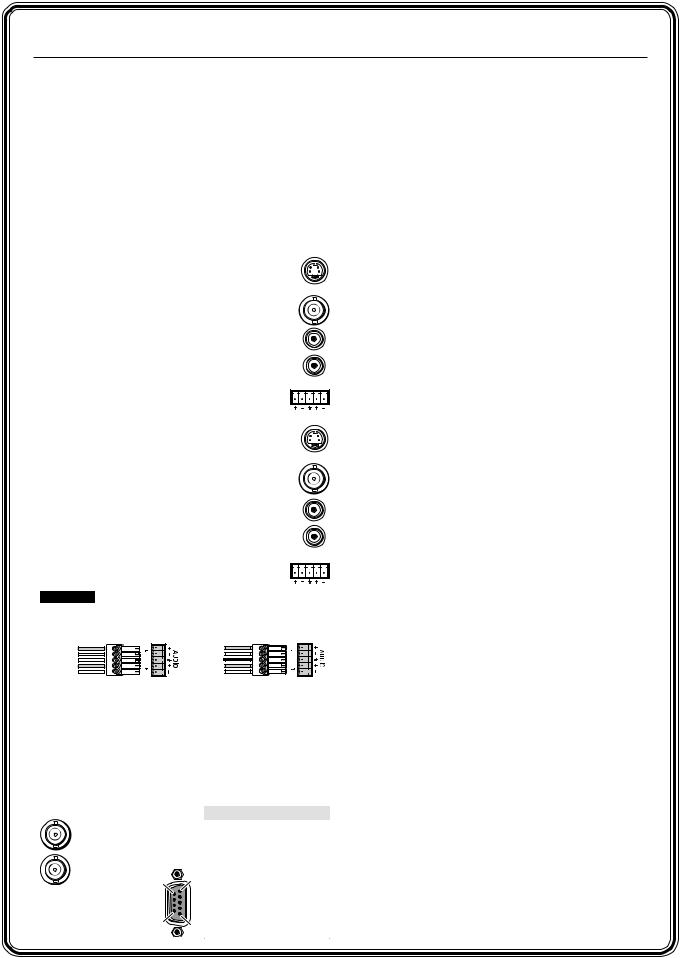
Step 2 — Inputs
As applicable to your switcher, connect:
a Up to 4 or 8 S-video inputs to the input connectors.
— or — Up to 4 or 8 composite video inputs to the input connectors.
b Up to 4 or 8 unbalanced stereo audio inputs to the input RCA connectors.
— or — Up to 4 or 8 balanced or
unbalanced stereo audio inputs to |
L |
1 R |
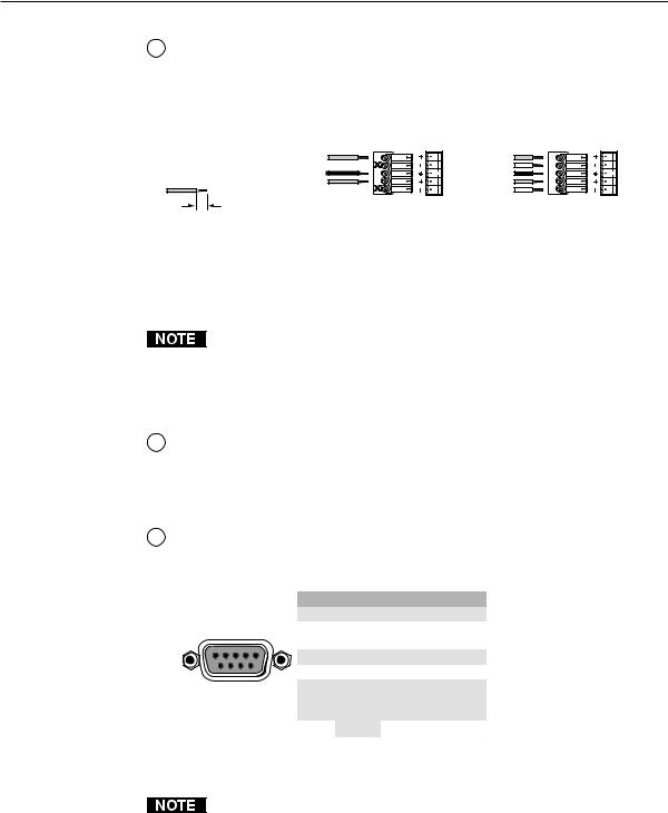
the input captive screw connectors.
Step 3 — Outputs
As applicable to your switcher, connect:
a Up to 4 or 8 S-video or composite video devices to the output connectors.
b Up to 4 or 8 unbalanced stereo audio devices to the output RCA connectors.
— or — Up to 4 or 8 balanced or unbalanced
stereo audio devices to the output |
L |
1 R |
captive screw connectors.
CAUTION Connect the sleeve to ground. Connecting the sleeve to a negative (-) terminal will
damage the audio output circuits.
Tip |
Tip |
See caution |
Ring |
Sleeve |
Sleeve (s) |
Tip |
Tip |
See caution |
Ring |
Unbalanced Output |
Balanced Output |
Step 4 — RS-232 Connections
If desired, connect a control system or a computer to the RS-232 port. See the table below
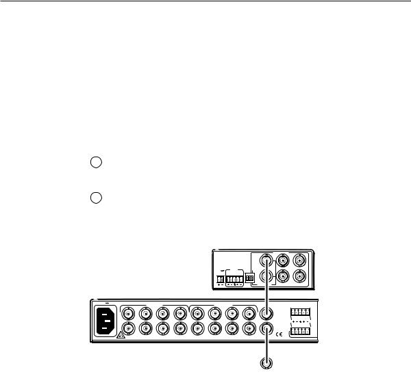
Step 5 — External Sync
If desired, feed a black burst (genlock) signal to the external sync
IN connectors.
OUT
6 1
9 5
Pin RS-232 Function
1 |
— |
N/C |
2 |
TX |
Transmit data |
3 |
RX |
Receive data |
|
|
|
4 |
— |
N/C |
5 |
Gnd |
Signal ground |
|
|
|
6 |
— |
N/C |
7 |
— |
N/C |
8 |
— |
N/C |
9 |
— |
Hardwired IR |
|
|
|
Step 6 — Connect power
Definitions
Tie — An input-to-output connection
Set of ties — An input tied to two or more outputs
Configuration — One or more ties or sets of ties
Current configuration — The currently active configuration (also called configuration 0)
Preset — A configuration that has been stored. One preset can be assigned to each input and output button. 16 presets are available via RS-232 control. When a preset is retrieved from memory, it becomes the current configuration.
Front Panel Features
Power/data/audio LED — Indicates power is applied. This LED also has two secondary functions:
Serial communication function — The Power/ data/audio LED blinks off and on to indicate that an IR signal has been received.
Audio level function — In Audio Setup mode, the Power/data/audio LED lights when the selected input audio signal is at or above the reference level and is unlit when the signal is below the reference level. Adjust the gain until the LED blinks frequently. If the LED is almost always lit, blinking off only occasionally, the level is too high. If the LED is almost always off, blinking on (lit) only occasionally, the level is too low.
I/O button (audio/video switchers) selects video and audio, video, or audio for input selection.
Video and Audio LEDs (audio/video switchers) indicate whether video and audio, video, or audio is selected. The Audio LED blinks to indicate audio is broken away.
Input buttons select an input to tie to an output.
Input LEDs identify the input selected for the tie.
Output buttons select output(s) to tie to an input.
Output LEDs identify output(s) selected for the tie.
Enter button saves configuration changes.
Preset button selects Save Preset mode or Recall Preset mode, in which a configuration can be saved as a preset or recalled.
Audio Setup button and LED enable you to view and/or change the current audio level setting for each input. Audio Setup is a secondary input function of the I/O button.
MAV 44 / 48 / 84 / 88 Matrix Switchers • Quick Start QS-1

Quick Start — MAV Series AV Matrix Switchers, cont’d
Down ( ) and Up (
 ) buttons and LEDs decrease or increase the audio level for the selected input and indicate the decrease and increase. On 8-output switchers,
  and
and  are secondary functions of the Output 7 and Output 8 buttons.
+dB/–dB LEDs indicate the polarity of the audio level setting (+dB = gain, –dB = attenuation).
+dB and –dB are secondary functions of the Video and Audio LEDs.
Each audio input gain and attenuation indicator indicates a range of 6 dB when lit. (Output 1 LED off = 0 dB to 5 dB, Output 1 lit = 6 dB to 11 dB, Output 1 and 2 lit = 12 dB to 17 dB, Output 1 through 3 lit = 18 dB.) The level indicators are secondary functions of the Output 1 through Output 3 LEDs.
Operation
Powering on
Plug in the switcher to apply power. The switcher’s self-test sequences the front panel LEDs.
Creating a tie
1. Press and release the I/O |
Press the button to cycle |
|
through the selections. |
||
button to select or deselect |
|
|
video and/or audio as |
I/O |
|
desired. |
The LEDs light when video VID |
|
|
and/or audio is selected. AUD |
|
Saving or recalling a preset
1. To Save a preset: Press and hold the Preset button until the Preset LED starts blinking.
To recall a preset: Press and release the Preset button.
PRESET |
PRESET |
Save |
2 seconds |
Press and hold. |
|
|
Preset LED blinks. |
Release the Preset button. |
|
PRESET |
PRESET |
Recall
Press and release.  Preset LED lights.
2. Press the desired input or output button.
Press and release the input 1 button to select preset 1 to save or recall.
INPUTS
1 |
2 |
3 |
4 |
PRESET
The Preset LED and Input 1 LED light for 1 second then go out.
2. Press and release the desired input button*.
3. Press and release the desired output button(s)*.
Press and release the Input 5 button.
INPUTS
4 |
5 |
6 |
The Input 5 LED lights to indicate that input 5 is selected.
Press and release the Output 3, 4, and 8 buttons.
|
OUTPUTS |
|
|
3 |
4 |
5 |
8 |
The LEDs blink to indicate that the selected input will be tied to these outputs.
 = Blinking button
*You can cancel the entire set of ties at this point by waiting for the 5-second input/ output button timeout to occur.
4. Press and release the Enter button. The selected input’s and the selected outputs’ LEDs light steadily for approximately 1 second to indicate the tie and then go out.
5 1 2 3
The input |
The Output 1 through 3 |
LED lights. |
LEDs display the input's |
|
audio level range. |
= lit, = unlit |
|
 +dB +/–dB LEDs
  -dB show polarity.
Power blinks to show the signal level.
4. Increase and decrease the audio input gain by pressing the  and
and  buttons until the audio level indicator (Power LED) blinks frequently.
5. For other inputs, repeat steps 3 and 4.
6. Press and release the Audio Setup button to exit.
QS-2 MAV 44 / 48 / 84 / 88 Matrix Switchers • Quick Start

Table of Contents
Chapter 1 • Introduction ....................................................................................................... |
1-1 |
About the Switchers ......................................................................................................... |
1-2 |
Features ................................................................................................................................... |
1-3 |
Video features .................................................................................................................... |
1-3 |
Audio features ................................................................................................................... |
1-4 |
Common features .............................................................................................................. |
1-4 |
Chapter 2 • Installation .......................................................................................................... |
2-1 |
Mounting the Switcher.................................................................................................... |
2-2 |
Tabletop use ....................................................................................................................... |
2-2 |
Rack mounting the switcher ............................................................................................. |
2-2 |
UL requirements .................................................................................................................. |
2-2 |
Mounting instructions ........................................................................................................ |
2-2 |
Furniture mounting the switcher ..................................................................................... |
2-3 |
Cabling and Rear Panel Views...................................................................................... |
2-4 |
Video input and output connections ................................................................................ |
2-4 |
Audio input and output connections (audio/video models) ........................................... |
2-5 |
Remote connection ............................................................................................................ |
2-6 |
External sync connection ................................................................................................... |
2-7 |
Power connection .............................................................................................................. |
2-8 |
Chapter 3 • Operation ............................................................................................................. |
3-1 |
Front Panel Controls and Indicators ......................................................................... |
3-2 |
Definitions .......................................................................................................................... |
3-3 |
Power/data/audio LED and infrared sensor ...................................................................... |
3-3 |
Input and output selection controls and indicators ........................................................ |
3-4 |
Control buttons and LEDs ................................................................................................. |
3-4 |
I/O selection and audio/video controls and indicators (audio/video switchers) ............. |
3-5 |
Operations .............................................................................................................................. |
3-6 |
Powering up the switcher ................................................................................................. |
3-6 |
Creating a set of ties .......................................................................................................... |
3-7 |
Example 1: Create a set of video and audio ties ........................................................... |
3-8 |
Example 2: Add a video tie to a set of video and audio ties ......................................... |
3-9 |
Example 3: Remove a tie from a set of ties ................................................................. |
3-11 |
Viewing the configuration .............................................................................................. |
3-12 |
Example 4: View ties by selecting an input ................................................................. |
3-13 |
Example 5: View ties by selecting outputs .................................................................. |
3-14 |
Using presets .................................................................................................................... |
3-16 |
Example 6: Save a preset ............................................................................................ |
3-17 |
Example 7: Recall a preset .......................................................................................... |
3-18 |
Adjusting input audio gain and attenuation ................................................................. |
3-19 |
Example 8: Adjust the input audio gain ..................................................................... |
3-21 |
Resetting audio gain — single input ......................................................................... |
3-23 |
Resetting audio gain — all inputs .............................................................................. |
3-24 |
Setting the output audio level ................................................................................... |
3-24 |
MAV 44 / 48 / 84 / 88 Matrix Switchers • Table of Contents |
i |

Table of Contents, cont’d
Front panel security lockout (Executive mode) .............................................................. |
3-25 |
Clearing all ties and presets ............................................................................................ |
3-25 |
Resetting the system to factory defaults (audio/video switchers) ................................ |
3-26 |
Memory ............................................................................................................................ |
3-26 |
Optimizing the Audio (Audio/Video Switchers) ................................................ |
3-27 |
Troubleshooting ................................................................................................................ |
3-27 |
Worksheets .......................................................................................................................... |
3-28 |
Worksheet example 1: System equipment ..................................................................... |
3-28 |
Worksheet example 2: Daily configuration .................................................................... |
3-29 |
Worksheet example 3: Test configuration ...................................................................... |
3-30 |
Configuration worksheet ................................................................................................ |
3-31 |
Chapter 4 • Remote Operation.......................................................................................... |
4-1 |
Simple Instruction Set Control .................................................................................... |
4-2 |
Host-to-switcher instructions ............................................................................................ |
4-2 |
Switcher-initiated messages .............................................................................................. |
4-3 |
Switcher error responses ................................................................................................... |
4-4 |
Using the command/response table ................................................................................. |
4-4 |
Symbol definitions ........................................................................................................ |
4-4 |
Command/response table for SIS commands ................................................................ |
4-5 |
Loading firmware using an SIS command ...................................................................... |
4-10 |
Matrix Switchers Control Program .......................................................................... |
4-12 |
Installing the software .................................................................................................... |
4-12 |
Using the software .......................................................................................................... |
4-13 |
Overview .................................................................................................................... |
4-13 |
Updating the firmware............................................................................................... |
4-15 |
Windows buttons, drop boxes, and the trash can ...................................................... |
4-18 |
Windows menus ......................................................................................................... |
4-19 |
File menu .......................................................................................................... |
4-19 |
Tools menu ........................................................................................................ |
4-19 |
Audio-input Configuration selection ................................................................ |
4-20 |
Preferences menu ............................................................................................. |
4-20 |
Master-Reset selection ...................................................................................... |
4-21 |
Using Emulation mode .................................................................................................... |
4-22 |
Using the help system ...................................................................................................... |
4-22 |
ii MAV 44 / 48 / 84 / 88 Matrix Switchers • Table of Contents

Appendix A • Specifications and Part Numbers................................................... |
A-1 |
Specifications....................................................................................................................... |
A-2 |
Part Numbers ....................................................................................................................... |
A-6 |
MAV Series AV switchers .................................................................................................. |
A-6 |
Included parts ................................................................................................................... |
A-6 |
Replacement parts ............................................................................................................ |
A-6 |
Optional accessories ......................................................................................................... |
A-7 |
Cables ................................................................................................................................ |
A-7 |
Bulk cable .................................................................................................................... |
A-7 |
Assorted connectors .................................................................................................... |
A-8 |
Pre-cut cables .............................................................................................................. |
A-8 |
MAV 44 / 48 / 84 / 88 Matrix Switchers • Table of Contents |
iii |

Table of Contents, cont’d
68-777-01 Rev. D
All trademarks mentioned in this manual are the properties of their respective owners. |
10 07 |
iv MAV 44 / 48 / 84 / 88 Matrix Switchers • Table of Contents

 MAV 44 / 48 / 84 / 88 Matrix Switchers
Chapter1One
Introduction
About the Switchers
Features
Introductiontroduction, cont’d
About the Switchers
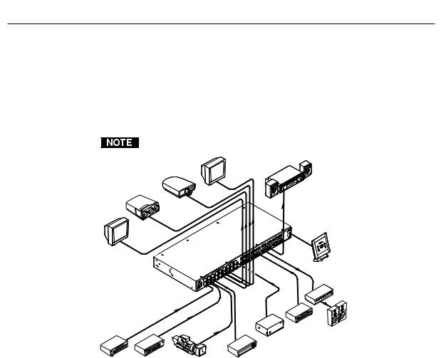
The Extron MAV Series AV matrix switchers (figure 1-1) are a family of broadcast quality matrix switchers that distribute any composite video or S-video input with audio to any combination of outputs. The MAV Series switchers can route multiple input/output ties simultaneously. The MAV Series switchers have a wide array of input and output configurations, video formats, and audio connections. Depending on the model, the switchers route a combination of S-video or composite video with audio on captive screw or RCA connectors.
The MAV 88 matrix size has models without audio.
Monitor
LCD
Projector
CRT
Projector
Monitor
Extron
MAV 88 AV
Matrix Switcher
DVD |
VCR |
Video Camera Laserdisc Player |
|
Sound System |
|
88 AV |
MAV |
RS232 |
System Control
|
Amplifier |
|
CD Player |
Speakers |
|
Extron |
||
|
||
BBG 6 A |
|
Blackburst Video Generator
Figure 1-1 — Typical MAV 88 AV application
The table on the following page lists the models and the combinations of inputs and outputs available in the MAV Series switcher family.
The MAV switcher can be locally controlled on the front panel or remotely controlled via its rear panel RS-232 serial port or an optional IR 501 Small Matrix Infrared (IR) Remote Control (part # 70-336-01).
1-2 MAV 44 / 48 / 84 / 88 Matrix Switchers • Introduction

|
|
|
Inputs |
|
|
|
Outputs |
|
|
||
Model |
Part # |
|
|
Captive |
|
RCA |
|
|
Captive |
|
RCA |
|
|
|
|
|
|
||||||
Video |
S-video |
screw |
|
Video |
S-video |
screw |
|
||||
|
|
|
audio |
|
audio |
||||||
|
|
|
|
audio |
|
|
|
|
audio |
|
|
MAV 44 SVA |
60-553-22 |
No |
4 |
4 |
|
No |
No |
4 |
4 |
|
No |
MAV 44 SVA RCA |
60-553-32 |
No |
4 |
No |
|
4 |
No |
4 |
No |
|
4 |
MAV 44 AV |
60-553-21 |
4 |
No |
4 |
|
No |
4 |
No |
4 |
|
No |
MAV 44 AV RCA |
60-553-31 |
4 |
No |
No |
|
4 |
4 |
No |
No |
|
4 |
MAV 48 SVA |
60-605-22 |
No |
4 |
4 |
|
No |
No |
8 |
8 |
|
No |
MAV 48 SVA RCA |
60-605-32 |
No |
4 |
No |
|
4 |
No |
8 |
No |
|
8 |
MAV 48 AV |
60-605-21 |
4 |
No |
4 |
|
No |
8 |
No |
8 |
|
No |
MAV 48 AV RCA |
60-605-31 |
4 |
No |
No |
|
4 |
8 |
No |
No |
|
8 |
MAV 84 SVA |
60-554-22 |
No |
8 |
8 |
|
No |
No |
4 |
4 |
|
No |
MAV 84 SVA RCA |
60-554-32 |
No |
8 |
No |
|
8 |
No |
4 |
No |
|
4 |
MAV 84 AV |
60-554-21 |
8 |
No |
8 |
|
No |
4 |
No |
4 |
|
No |
MAV 84 AV RCA |
60-554-31 |
8 |
No |
No |
|
8 |
4 |
No |
No |
|
4 |
MAV 88 SV |
60-555-02 |
No |
8 |
No |
|
No |
No |
8 |
No |
|
No |
MAV 88 SVA |
60-555-22 |
No |
8 |
8 |
|
No |
No |
8 |
8 |
|
No |
MAV 88 SVA RCA |
60-555-32 |
No |
8 |
No |
|
8 |
No |
8 |
No |
|
8 |
MAV 88 V |
60-555-01 |
8 |
No |
No |
|
No |
8 |
No |
No |
|
No |
MAV 88 AV |
60-555-21 |
8 |
No |
8 |
|
No |
8 |
No |
8 |
|
No |
MAV 88 AV RCA |
60-555-31 |
8 |
No |
No |
|
8 |
8 |
No |
No |
|
8 |
Features
Video features
S-video (SV) models — These switchers input and output NTSC 3.58, NTSC 4.43, PAL, or SECAM S-video (luminance [Y] and chrominance [C]) signals on 4-pin female mini DIN connectors.
Composite video (V) models — These switchers input and output NTSC 3.58, NTSC 4.43, PAL, and SECAM composite video signals on female BNC connectors.
Bandwidth (SV and V models) — Bandwidth is 150 MHz (-3 dB). This high bandwidth allows the switchers to switch all of the quad-standard video formats with no loss of signal quality.
Vertical interval switching — The switcher can use a black burst (genlock) signal to synchronize switching during the vertical interval. This ensures glitch-free switching among multiple timed sources.
MAV 44 / 48 / 84 / 88 Matrix Switchers • Introduction |
1-3 |

Introduction, cont’d
Audio features
Captive screw audio connector (A) models — These switchers input and output balanced or unbalanced stereo audio signals, on 3.5 mm, 5-pole captive screw terminals.
RCA audio connector (A RCA) models — These switchers input and output unbalanced stereo audio signals on left and right RCA connectors.
Audio input gain/attenuation — You can set the level of audio gain or attenuation (+10 dB to –18 dB) via the RS-232 port or from the front panel. Individual input audio levels can be adjusted so there are no noticeable volume differences between sources and for the best headroom and signal-to-noise ratio. This function also eliminates the need for separate preamps or attenuators when used with professional (higher line level) and consumer (lower line level) audio equipment.
Audio output level switch — The audio level of each output can be set to either –10 dBV (consumer level) or +4 dBu (pro level) via RS-232 control only.
Audio follow — In audio/video switchers, audio can be switched with the corresponding video input. Audio follow switching can be done via front panel control, optional IR 501 control, or the RS-232 port.
Audio breakaway — In audio/video switchers, audio can be broken away from its corresponding video input signal. Audio breakaway switching can be done via front panel control, optional IR 501 control, or the RS-232 port.
Common features
Switching flexibility — Provides individually buffered, independent matrix switched outputs with audio follow and audio breakaway for audio versions.
•Any input to any or all outputs
•Quick multiple tie — Multiple inputs can be switched to multiple outputs simultaneously. This allows all displays (outputs) to change from source to source at the same time.
Operational flexibility — Operations such as input/output selection and setting of presets can be performed on the front panel, via the RS-232 port, or using the optional IR 501 small matrix universal remote control. The RS-232 port allows remote control via a PC or control system.
•Front panel controller — The MAV series front panel controller feature supports touch-of-a-button input and output selection, preset creation and selection, and audio gain and attenuation control.
•RS-232 control — The switcher’s RS-232 port allows remote control via a PC or control system using Extron’s Simple Instruction Set (SIS™) or the included Windows®-based control program.
•Optional IR remote control — The MAV switchers are remote controllable, using the optional small matrix IR remote control.
The switcher’s IR receiver is disabled by default and must be enabled to use the IR remote control. See the IR receiver enable SIS command in chapter 4, “Remote Operation” to enable the IR receiver.
Upgradeable firmware — The firmware that controls the switcher’s operation can be upgraded in the field via the RS-232 port, without taking the switcher out of service. Firmware upgrades are available for download on the Extron Web site, www.extron.com, and they can be installed using the Windows-based control program.
1-4 MAV 44 / 48 / 84 / 88 Matrix Switchers • Introduction

Global memory presets — 16 global memory presets are a time-saving feature that lets you set up and store input/output configurations in advance. You can then recall those configurations, when needed, with a few simple steps. On each model, there are as many presets available from the front panel as there are input and output buttons:
•MAV 44s have 8 presets available on the front panel.
•MAV 48s and MAV 84s have 12 presets available on the front panel.
•MAV 88s have 16 presets available on the front panel.
On smaller MAVs, presets that are not available from the front panel are still available under RS-232 or optional IR 501 control.
Rack mountable — With the included rack mounting kit, the switchers can be mounted in any conventional 19” wide rack.
Under-desk mountable — With an optional desk mounting kit, the switchers can be mounted under a desk, podium, or other furniture.
Front panel security lockout (executive mode) — If a MAV Series switcher is installed in an open area where operation by unauthorized personnel may be a problem, a security lock-out feature can be implemented. When the front panel is locked, a special button combination is required to unlock the front panel controller before it can be operated. Ties can still be viewed.
When the front panel is locked out, the switcher can still be operated via the RS-232 link.
Power supply — The matrix switchers’ internal 100 VAC to 240 VAC, 50/60 Hz, 15 watts, auto-switchable power supply provides worldwide power compatibility.
MAV 44 / 48 / 84 / 88 Matrix Switchers • Introduction |
1-5 |

Introduction, cont’d
1-6 MAV 44 / 48 / 84 / 88 Matrix Switchers • Introduction


 MAV 44 / 48 / 84 / 88 Matrix Switchers
Chapter2Two
Installation
Mounting the Switcher
Cabling and Rear Panel Views

Installationstallation, cont’d
Mounting the Switcher
Keep the switcher out of bright light to prevent interference with the IR signals from the IR 501 remote control.
Tabletop use
For tabletop use, affix a self-adhesive rubber foot to each corner of the bottom of the switcher.
Rack mounting the switcher
UL requirements
The following Underwriters Laboratories (UL) requirements pertain to the installation of the matrix switcher into a rack (figure 2-1).
1.Elevated operating ambient temperature — If installed in a closed or multiunit rack assembly, the operating ambient temperature of the rack environment may be greater than room ambient. Therefore, consider installing the equipment in an environment compatible with the maximum ambient temperature (Tma) specified by the manufacturer.
2.Reduced air flow — Installation of the equipment in a rack should be such that the amount of air flow required for safe operation of the equipment is not compromised.
3.Mechanical loading — Mounting of the equipment in the rack should be such that a hazardous condition is not achieved due to uneven mechanical loading.
4.Circuit overloading — Consideration should be given to the connection of the equipment to the supply circuit and the effect that overloading of the circuits might have on overcurrent protection and supply wiring. Appropriate consideration of equipment nameplate ratings should be used when addressing this concern.
5.Reliable earthing (grounding) — Reliable earthing of rack-mounted equipment should be maintained. Particular attention should be given to supply connections other than direct connections to the branch circuit (e.g. use of power strips).
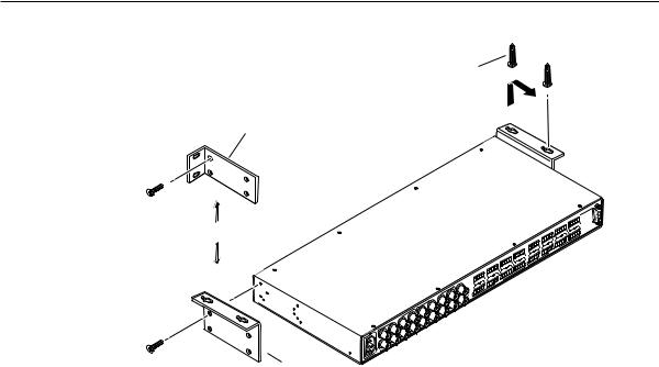
Mounting instructions
All of the MAV Series AV switcher models are housed in rack-mountable, 1U-high, full-rack wide metal enclosures. The appropriate rack mounting kit is included with each switcher. Rack mount the switcher as follows:
1. |
If feet were previously installed on the bottom of the switcher, remove them. |
2. |
Attach the rack mount brackets to the switcher with the eight #8 machine |
|
screws provided (figure 2-1). |
3. |
Insert the switcher into the rack, aligning the holes in the mounting bracket |
|
with those of the rack. |
4. |
Secure the switcher to the rack using the supplied machine screws. |
2-2 MAV 44 / 48 / 84 / 88 Matrix Switchers • Installation
Mounting Screws (2 Plcs)
Each Side
Rack-mount
Bracket (Included)
Drill pilot holes 3/32” (2 mm) dia., 1/4” (6 mm) deep.
or
SYNC
IN
OUT
OUTPUTS |
8 |
|
7 |
|
5 |
|
6 |
3 |
|
4 |
|
1 2
INPUTS |
7 |
8 |
|
|
5 |
|
6 |
3 |
|
4 |
|
1 2
#8 Screw (4 Plcs) |
Table/ |
|
Wall-mount |
||
Each Side |
||
Bracket (Optional) |
||
|
|
|
R |
|
|
7 |
|
L |
R |
R |
L |
8 |
|
|
5 |
|
L |
R |
R |
L |
6 |
|
3 |
L |
R |
|
4 |
|
R |
L |
|
1 |
INPUTS |
L |
R |
2 L
|
|
R |
|
|
5 |
|
L |
R |
R |
L |
6 |
|
3 |
L |
R |
|
4 |
|
R |
L |
OUTPUTS |
|
2 |
|
|
|
1 |
|
|
L |
R |
|
|
L
MAV |
AV |
232RS |
|
|
88 |
|
R |
|
7 |
L |
R |
L |
8 |
Figure 2-1 — Mounting the switcher
Furniture mounting the switcher
The MAV Series switcher models can be mounted under a table or other horizontal surface with an optional Extron under-desk mounting kit (part #70-222-01).
1. |
Secure the two table/wall mounting brackets to the switcher with the eight |
|
machine screws provided in the kit (figure 2-1). |
2. |
Hold the switcher with attached brackets against the underside of the desk or |
|
other furniture. Mark the location of holes for screws on the underside of the |
|
desk. |
3. |
Drill 1/4" (6.4 mm) deep, 3/32" (2 mm) diameter pilot holes in the table or |
|
desk at the marked screw locations from the underside/inside (concealed |
|
side) of the furniture, where the switcher will be located. |
4. |
Insert the four wood screws into the pilot holes. Fasten each screw into the |
|
installation surface until just less than 1/4" of the screw head protrudes. |
5. |
Align the installed screws with the slots in the mounting brackets, and place |
|
the switcher against the surface, with the screws through the bracket slots. |
6. |
Slide the switcher slightly forward or back, then tighten all four screws to |
|
secure it in place. |
MAV 44 / 48 / 84 / 88 Matrix Switchers • Installation |
2-3 |
Installation, cont’d
Cabling and Rear Panel Views
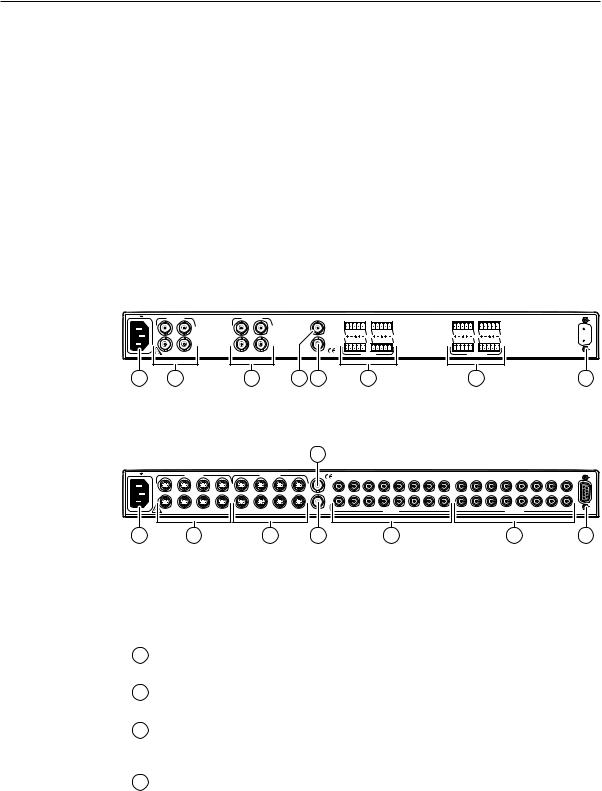
All connectors are on the rear panel. The switcher can be connected to up to eight S-video, composite video, and/or stereo audio sources, depending on the model. The switcher can output to up to eight S-video, composite video, and/or audio devices.
Figure 2-2 shows a MAV 44 AV composite video and audio switcher. Figure 2-3 shows a MAV 88 SVA RCA S-video and audio switcher. All of the switchers are housed in the same 1U enclosures, but have more or fewer input connectors to accommodate the different configurations they provide. The two switchers shown have all of the connector types that are available in the MAV AV product family covered in this manual.
Some devices, such as VCRs, can be connected to both video and audio input and output connectors of the switcher. Others, such as tape players or CD players, can be connected only to the audio input connectors. An audio device and a separate video device can share an input, because the switcher is capable of switching video and audio separately (audio breakaway).
100-240V 0.3A |
INPUTS |
|
|
|
|
|
1 |
3 |
|
2 |
4 |
50-60Hz |
|
12 |
1 |
OUTPUTS
13
24
3 |
SYNC |
|
|
|
|
|
|
|
|
|
IN |
L 1 |
R |
L 3 |
R |
L 1 |
R |
L 3 |
R |
|
OUT |
L |
2 |
R |
L 4 |
R |
L 2 |
R |
L 4 |
R |
|
|||||||||
|
|
|
INPUTS |
|
|
|
OUTPUTS |
|
|
10 |
11 |
5 |
7 |
MAV 44 AV
 RS-232
9
Figure 2-2 — MAV 44 AV composite video switcher with audio
|
|
|
|
|
|
|
|
|
10 |
|
|
|
|
|
|
|
|
|
|
|
|
100-240V |
0.3A |
|
INPUTS |
|
|
|
OUTPUTS |
|
SYNC |
|
|
|
|
|
|
|
|
|
|
|
|
|
|
|
|
|
|
|
|
3 |
|
5 |
|
|
8 |
|
|
|
4 |
5 |
|||
|
|
|
|
|
|
|
|
|
1 |
2 |
4 |
6 |
7 |
1 |
2 |
3 |
|||||
|
1 |
|
5 |
7 |
1 |
|
|
7 |
L |
|
|
|
|
|
|
|
|
|
|
|
|
|
3 |
3 |
5 |
IN |
|
|
|
|
|
|
|
|
|
|
|
|
|||||
|
2 |
4 |
6 |
8 |
2 |
4 |
6 |
8 |
OUT |
|
|
|
|
|
|
|
|
|
|
|
|
|
|
|
|
|
|
|
|
|
R |
|
|
|
|
|
|
|
|
|
|
|
|
50-60Hz |
|
|
|
|
|
|
|
|
|
|
INPUTS |
|
|
|
|
|
|
|
OUTPUTS |
|
|
12 |
2 |
4 |
11 |
6 |
8 |
MAV 88 SVA RCA
6 |
7 |
8 |
|
|
RS-232 |
9
Figure 2-3 — MAV 88 SVA RCA S-video switcher with audio on RCA connectors
Video input and output connections
1Composite video inputs (composite video [V] switchers only) — For each input, connect a composite video source to one of these BNC connectors.
2S-video inputs (S-video [SV] switchers only) — For each input, connect an S-video source to one of these 4-pin mini DIN connectors.
3Composite video outputs (composite video [V] switcher models only) —
Connect a composite video display or other device to these BNC connectors for each composite video output.
4S-video output (S-video [SV] switchers only) — Connect an S-video display or other device to this 4-pin mini DIN connector for each S-video output.
2-4 MAV 44 / 48 / 84 / 88 Matrix Switchers • Installation
Audio input and output connections (audio/video models)
The audio level for each input can be individually set, via the front panel or RS-232, to ensure that the level on the output does not vary from input to input. See chapter 3, “Operation”, and chapter 4, “Remote Operation” for details.
By default, the audio follows the video switch. Audio breakaway, which is commanded via the front panel, under RS-232 control via the SIS or Windowsbased control program, or optional IR 501 control, allows you to select from any one of the audio input sources. For details, see chapter 3, “Operation”, and chapter 4, “Remote Operation”, and refer to the IR 501 Small Matrix IR Remote Control User’s Guide.
5Balanced or unbalanced audio input connections (captive screw audio connector [A] models only) — Each input has a 3.5 mm, 5-pole captive screw connector for balanced or unbalanced stereo audio input. Connectors are included with each MAV AV captive screw connector switcher, but you must supply the audio cable. See figure 2-4 to wire a connector for the appropriate input type and impedance level. High impedance is generally over 5 k ohms.
Figure 2-4 shows two methods of wiring the captive screw audio connectors for input and figure 2-6 shows two methods of wiring the connectors for output. A mono audio connector consists of the tip and sleeve. A stereo audio connector consists of the tip, ring, and sleeve. If you are wiring a captive screw connector from an existing unbalanced audio cable, the white insulated wire is typically the left channel (tip) and the red insulated wire is typically the right channel (sleeve). There is no reliable standard for existing balanced audio cables.
|
Tip |
L |
|
Sleeve |
|
|
|
|
|
Tip |
R |
|
Sleeve |
|
|
|
|
3/16” (5 mm) Max. Unbalanced Stereo Input |
||
Do not tin the wires! |
|
(high impedance) |
Tip |
L |
|
Ring |
||
|
||
Sleeve (s) |
|
|
Tip |
R |
|
Ring |
||
|
Balanced Stereo Input
(high impedance)
Figure 2-4 — Captive screw connector wiring for audio inputs
The length of exposed wires is critical. The ideal length is 3/16” (5 mm).
•If the stripped section of wire is longer than 3/16”, the exposed wires may touch, causing a short circuit between them.
•If the stripped section of wire is shorter than 3/16”, wires can be easily pulled out even if tightly fastened by the captive screws.
6RCA connector audio inputs (RCA audio connector [A RCA] models only) —
Each input has a pair (left and right) of RCA connectors for unbalanced stereo audio input (figure 2-5).
Tip (Signal) |
|
Right Channel |
Tip (+) |
(Red Jacket) |
|
Sleeve (Gnd ) |
|
Left Channel |
Sleeve ( ) |
(White Jacket) |
|
Figure 2-5 — RCA connector wiring
MAV 44 / 48 / 84 / 88 Matrix Switchers • Installation |
2-5 |
Installation, cont’d
7Balanced or unbalanced audio output connectors (captive screw audio connector [A] models only) — These 3.5 mm, 5-pole captive screw connectors output the selected unamplified, line level audio. Connect audio devices, such as an audio amplifier or powered speakers to these connectors. See figure 2-6 to properly wire an output connector.
Tip |
L |
Left |
Tip |
L |
Left |
|
NO GROUND HERE. |
Ring |
|||||
|
|
|
|
|||
Sleeve(s) |
|
|
Ground |
|
|
|
Tip |
R |
Right |
Tip |
R |
Right |
|
NO GROUND HERE. |
Ring |
|||||
|
|
|
|
3/16” (5 mm) Max. Unbalanced Stereo Output |
Balanced Stereo Output |
Do not tin the wires!
Figure 2-6 — Captive screw connector wiring for audio output
CAUTION |
Connect the sleeve to ground (Gnd). Connecting the sleeve to a negative |
|
(-) terminal will damage the audio output circuits. |
The length of exposed wires is critical. The ideal length is 3/16” (5 mm).
•If the stripped section of wire is longer than 3/16”, the exposed wires may touch, causing a short circuit between them.
•If the stripped section of wire is shorter than 3/16”, wires can be easily pulled out even if tightly fastened by the captive screws.
8RCA connector audio output (RCA connector audio [A RCA] models only) —
The switcher has a pair (left and right) of RCA connectors for each unbalanced stereo audio output (figure 2-5).
Remote connection
9RS-232 connector — Connect a host device, such as a computer or control system, to the switcher via this 9-pin D connector (figure 2-7) for remote control of the switcher.
|
|
Pin |
RS-232 |
Function |
|
|
|
1 |
— |
Not used |
|
5 |
1 |
2 |
TX |
Transmit data |
|
3 |
RX |
Receive data |
|||
|
|
||||
|
|
4 |
— |
Not used |
|
|
|
5 |
Gnd |
Signal ground |
|
9 |
6 |
6 |
— |
Not used |
|
Female |
7 |
— |
Not used |
||
|
|
8 |
— |
Not used |
|
|
|
9 |
— |
Hardwired IR input |
|
Figure 2-7 — RS-232 port pin assignment
The cable used to connect the RS-232 port to a computer or control system may need to be modified by removing pins or cutting wires. If you encounter problems while operating under RS-232 control (the switcher may hang up), pins 1, 4, 6, 7, 8, and 9 may need to be disconnected. Either cut the wire to pins 1, 4, and 6 through 9 in a hard-shelled connector or remove pins 1, 4, and 6 through 9 from a molded plug.
See chapter 4, “Remote Operation”, for definitions of the SIS commands and details on how to install and use the control software.
2-6 MAV 44 / 48 / 84 / 88 Matrix Switchers • Installation
Using the hardwired IR input on pin 9, you can use a control system with IR-learning capabilities to operate the switcher just as if you were using an IR 501 remote control. The control system must first “learn” the IR command from an IR 501, after which it sends the same commands to the MAV via
pin 9.
External sync connection
The MAV switcher switches between inputs during the vertical interval period, resulting in glitch-free video switching. The MAV switcher can use an external signal to synchronize switching during the vertical interval. Without the external sync locking feature, switching between inputs can result in a brief rolling (sync loss) or a brief change in the picture size.
10Sync In connector — Connect an external genlock signal to this BNC connector for genlocking the video signal in broadcast or other sync-critical applications.
11Sync Out connector — Connect any downstream equipment that requires genlocking to this BNC connector to route the external sync signal throughout the system in broadcast or other sync-critical applications.
Figure 2-8 shows a basic external sync configuration.
|
|
|
|
|
BBG 6 A |
|
|
|
|
BLACKBURST |
|
|
|
|
||
|
|
|
|
|
|
+4 |
NTSC |
BLACKBURST |
|
|
|
|
|
|||
|
|
|
|
|
12V |
|
AUDIO |
|
|
|
|
|
|
|||
|
|
|
|
|
BLACKBURST AND AUDIO |
|
|
|
|
|
|
|
|
|||
|
|
|
|
|
GENERATOR |
|
|
|
|
|
|
|
|
|
||
|
|
|
|
|
POWER |
1 KHZ |
|
|
|
|
1 |
3 |
|
|
5 |
|
|
|
|
|
|
|
|
|
|
|
|
|
|
|
|
|
|
|
|
|
|
|
.2A MAX |
L |
R |
ON |
|
|
|
|
|
|
|
|
|
|
|
|
|
|
|
|
|
1 |
2 |
3 |
2 |
4 |
|
|
6 |
|
|
|
|
|
|
|
|
|
10- |
PAL |
|
COLORBARS |
|
|
|
|
100-240V |
0.3A |
INPUTS |
|
|
OUTPUTS |
|
|
|
|
SYNC |
|
|
|
|
||
|
|
|
|
|
|
|
|
|
|
|
|
|||||
|
1 |
3 |
5 |
7 |
1 |
3 |
|
5 |
|
|
7 |
IN |
|
L 1 R |
||
|
2 |
4 |
6 |
8 |
2 |
4 |
|
6 |
|
|
8 |
OUT |
|
L |
2 |
R |
Extron
BBG 6 A
Black Burst/Color Bar/
Audio Generator
50-60Hz
Extron |
|
|
MAV 88 AV |
To next device |
|
Matrix Switcher |
||
or terminate. |
||
IN |
Figure 2-8 — Simple external sync connection example
MAV 44 / 48 / 84 / 88 Matrix Switchers • Installation |
2-7 |
Installation, cont’d
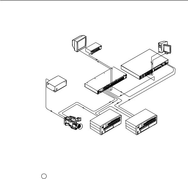
Figure 2-9 shows another configuration, in which the timing source passes through three video cameras and a video scan converter before connecting to the switcher. This type of video camera is capable of synchronizing with the external timing source for video editing applications.
Monitor |
Extron |
VGA Input |
|
VSC 900D
Computer-to-Video
Scan Converter
VCR
Extron
BBG 6 A
Black Burst/Color Bar/
Audio Generator
Extron 


MAV 88 AV
Matrix Switcher
Video Camera
Figure 2-9 — Multiple device external sync connection example
If no external sync timing source is connected to the switcher, switching occurs immediately after a front panel or RS-232 switch command is received.
Power connection
12AC power connector — Plug a standard IEC power cord into this connector to connect the switcher to a 100 VAC to 240 VAC, 50 or 60 Hz power source.
2-8 MAV 44 / 48 / 84 / 88 Matrix Switchers • Installation


 MAV 44 / 48 / 84 / 88 Matrix Switchers
Chapter3Three
Operation
Front Panel Controls and Indicators
Operations
Optimizing the Audio (Audio/Video Switchers)
Troubleshooting
Worksheets
Operationeration, cont’d
Front Panel Controls and Indicators
The number of input and output buttons and LEDs and other controls and LEDs that are present on each MAV Series AV matrix switcher vary with the number of inputs and outputs and whether the switcher has video only or both video and audio. Not every switcher has every control or indicator described in this chapter.
In the following descriptions, you will find the following terms:
•Video-only switcher — Switches S-video or composite video only and has no audio capabilities.
•Audio/video switcher — Switches either S-video or composite video and audio.
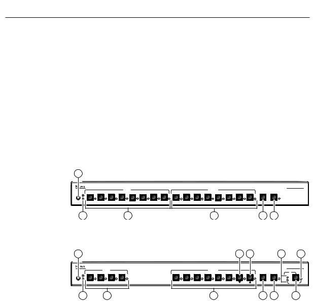
Figure 3-1 shows the front panel of an 8-input, 8-output video-only switcher. Figure 3-2 shows the front panel of a 4-input, 8-output video and audio switcher. These examples show all of the control and indicator combinations that you may encounter with your particular switcher.
Many of the buttons and LEDs on figure 3-2 have dual functions.
1
|
|
|
|
INPUTS |
|
|
|
|
|
|
|
OUTPUTS |
|
|
|
|
|
1 |
2 |
3 |
4 |
5 |
6 |
7 |
8 |
1 |
2 |
3 |
4 |
5 |
6 |
7 |
8 |
ENTER |
PRESET |
IR |
|
|
|
|
|
|
|
|
|
|
|
|
|
|
|
|
|
2 |
|
|
|
3 |
|
|
|
|
|
|
|
4 |
|
|
|
5 |
6 |
MAV SERIES
AV MATRIX SWITCHER
Figure 3-1 — MAV 88 V front panel
1 |
10 |
11 |
8 |
9 |
MAV SERIES
|
|
INPUTS |
|
|
|
|
|
OUTPUTS |
|
|
|
|
|
AV MATRIX SWITCHER |
1 |
2 |
3 |
4 |
1 |
2 |
3 |
4 |
5 |
6 |
7 |
8 |
ENTER |
PRESET |
I/O |
IR |
|
|
|
|
|
|
|
|
|
|
|
|
|
|
|
|
|
|
|
|
|
|
|
|
|
|
|
VID |
+dB |
|
|
|
|
|
|
|
|
|
|
|
|
|
AUD |
-dB |
|
|
|
|
|
|
|
|
|
|
|
|
|
|
AUDIO SETUP |
2 |
|
3 |
|
|
|
|
|
4 |
|
|
|
5 |
6 |
7 |
Figure 3-2 — MAV 48 SVA RCA front panel
3-2 MAV 44 / 48 / 84 / 88 Matrix Switchers • Operation

Definitions
The following terms, which apply to Extron matrix switchers, are used throughout this manual:
Tie — An input-to-output connection
Set of ties — An input tied to two or more outputs. (An output can never be tied to more than one input.)
Configuration — Consists of one or more ties or one or more sets of ties
Current configuration — The configuration that is currently active in the switcher (also called configuration 0)
Global memory preset — A configuration that has been stored. Up to 16 global memory presets can be stored in memory. The input and output buttons are used to select the desired preset memory location to load or retrieve a preset. When a preset is retrieved from memory, it becomes the current configuration. On each model, there are as many presets available from the front panel as there are input and output buttons:
•MAV 44 models have 8 presets available on the front panel.
•MAV 48 and MAV 84 models have 12 presets available on the front panel.
•MAV 88 models have 16 presets available on the front panel.
On smaller MAV models, presets that are not available from the front panel are still available under RS-232 or optional IR 501 control.
Power/audio/data LED and infrared sensor
1Infrared remote sensor — This sensor receives infrared (IR) signals from the optional IR 501 small matrix universal remote control. The IR remote control must be pointed within 30 degrees of this sensor for best results.
Operation of the IR 501 remote control is described in the IR 501 Small Matrix IR Remote Control User’s Guide.
The switcher’s IR receiver is disabled by default and must be enabled to use the IR remote control. See the IR receiver enable SIS command in chapter 4, “Remote Operation” to enable the IR receiver.
Keep the switcher out of bright light to prevent interference with the IR signals from the IR 501 remote control.
2Power/data/audio LED —
•When lit, the Power LED indicates that power is applied to the matrix switcher.
•When blinking off and on, the Power LED indicates that an IR signal has been received.
•In Audio Setup mode, the Power LED also serves as an audio meter that is tied to output 1. The LED blinks frequently when the selected input’s audio level has been adjusted to the –10 dBV internal reference level. (In Audio Setup mode, the selected input’s audio is automatically tied to output 1.) See “Adjusting input audio gain and attenuation” on
page 3-19 and “Optimizing the Audio (Audio/Video Switchers)” on page 3-27.
MAV 44 / 48 / 84 / 88 Matrix Switchers • Operation |
3-3 |
Loading...