


 Loading...
User’s Manual
|
|
Extron Electronics, USA |
|
Extron Electronics, Europe |
|
Extron Electronics, Asia |
|
Extron Electronics, Japan |
|
|
1230 South Lewis Street |
|
Beeldschermweg 6C |
|
135 Joo Seng Road, #04-01 |
|
Daisan DMJ Building 6F |
|
|
Anaheim, CA 92805 |
|
3821 AH Amersfoort |
|
PM Industrial Building |
|
3-9-1 Kudan Minami |
|
|
USA |
|
The Netherlands |
|
Singapore 368363 |
|
Chiyoda-ku, Tokyo 102-0074 Japan |
www.extron.com |
|
714.491.1500 |
|
+31.33.453.4040 |
|
+65.6383.4400 |
|
+81.3.3511.7655 |
|
Fax 714.491.1517 |
|
Fax +31.33.453.4050 |
|
Fax +65.6383.4664 |
|
Fax +81.3.3511.7656 |
|
|
|
|
|
MLS 100 A, MLS 102 VGA, MLS 103 V, MLS 103 SV
MediaLink™ VersaTools™ Switchers
68-652-01 Rev. A
Printed in the USA
03 03
© 2002. 2003 Extron Electronics. All rights reserved.
Precautions
Safety Instructions • English |
Warning |
|
This symbol is intended to alert the user of important operating and maintenance (servicing) instructions in the literature provided with the equipment.
This symbol is intended to alert the user of the presence of uninsulated dangerous voltage within the product's enclosure that may present a risk of electric shock.
Caution
Read Instructions • Read and understand all safety and operating instructions before using the equipment.
Retain Instructions • The safety instructions should be kept for future reference.
Follow Warnings • Follow all warnings and instructions marked on the equipment or in the user information.
Avoid Attachments • Do not use tools or attachments that are not recommended by the equipment manufacturer because they may be hazardous.
Power sources • This equipment should be operated only from the power source indicated on the product. This equipment is intended to be used with a main power system with a grounded (neutral) conductor. The third (grounding) pin is a safety feature, do not attempt to bypass or disable it.
Power disconnection • To remove power from the equipment safely, remove all power cords from the rear of the equipment, or the desktop power module (if detachable), or from the power source receptacle (wall plug).
Power cord protection • Power cords should be routed so that they are not likely to be stepped on or pinched by items placed upon or against them.
Servicing • Refer all servicing to qualified service personnel. There are no userserviceable parts inside. To prevent the risk of shock, do not attempt to service this equipment yourself because opening or removing covers may expose you to dangerous voltage or other hazards.
Slots and openings • If the equipment has slots or holes in the enclosure, these are provided to prevent overheating of sensitive components inside. These openings must never be blocked by other objects.
Lithium battery • There is a danger of explosion if battery is incorrectly replaced. Replace it only with the same or equivalent type recommended by the manufacturer. Dispose of used batteries according to the manufacturer's instructions.
Consignes de Sécurité • Français
Ce symbole sert à avertir l’utilisateur que la documentation fournie avec le matériel contient des instructions importantes concernant l’exploitation et la maintenance (réparation).
Ce symbole sert à avertir l’utilisateur de la présence dans le boîtier de l’appareil de tensions dangereuses non isolées posant des risques d’électrocution.
Attention
Lire les instructions• Prendre connaissance de toutes les consignes de sécurité et d’exploitation avant d’utiliser le matériel.
Conserver les instructions• Ranger les consignes de sécurité afin de pouvoir les consulter à l’avenir.
Respecter les avertissements • Observer tous les avertissements et consignes marqués sur le matériel ou présentés dans la documentation utilisateur.
Eviter les pièces de fixation • Ne pas utiliser de pièces de fixation ni d’outils non recommandés par le fabricant du matériel car cela risquerait de poser certains dangers.
Avertissement
Alimentations• Ne faire fonctionner ce matériel qu’avec la source d’alimentation indiquée sur l’appareil. Ce matériel doit être utilisé avec une alimentation principale comportant un fil de terre (neutre). Le troisième contact (de mise à la terre) constitue un dispositif de sécurité : n’essayez pas de la contourner ni de la désactiver.
Déconnexion de l’alimentation• Pour mettre le matériel hors tension sans danger, déconnectez tous les cordons d’alimentation de l’arrière de l’appareil ou du module d’alimentation de bureau (s’il est amovible) ou encore de la prise secteur.
Protection du cordon d’alimentation • Acheminer les cordons d’alimentation de manière à ce que personne ne risque de marcher dessus et à ce qu’ils ne soient pas écrasés ou pincés par des objets.
Réparation-maintenance • Faire exécuter toutes les interventions de réparationmaintenance par un technicien qualifié. Aucun des éléments internes ne peut être réparé par l’utilisateur. Afin d’éviter tout danger d’électrocution, l’utilisateur ne doit pas essayer de procéder lui-même à ces opérations car l’ouverture ou le retrait des couvercles risquent de l’exposer à de hautes tensions et autres dangers.
Fentes et orifices • Si le boîtier de l’appareil comporte des fentes ou des orifices, ceux-ci servent à empêcher les composants internes sensibles de surchauffer. Ces ouvertures ne doivent jamais être bloquées par des objets.
Lithium Batterie • Il a danger d'explosion s'll y a remplacment incorrect de la batterie. Remplacer uniquement avec une batterie du meme type ou d'un ype equivalent recommande par le constructeur. Mettre au reut les batteries usagees conformement aux instructions du fabricant.
Sicherheitsanleitungen • Deutsch
Dieses Symbol soll dem Benutzer in der im Lieferumfang enthaltenen Dokumentation besonders wichtige Hinweise zur Bedienung und Wartung (Instandhaltung) geben.
DiesesSymbolsolldenBenutzerdaraufaufmerksam machen, daß im Inneren des Gehäuses dieses ProduktesgefährlicheSpannungen,dienichtisoliert sind und die einen elektrischen Schock verursachen können, herrschen.
Achtung
Lesen der Anleitungen • Bevor Sie das Gerät zum ersten Mal verwenden, sollten Sie alle Sicherheits-und Bedienungsanleitungen genau durchlesen und verstehen.
Aufbewahren der Anleitungen • Die Hinweise zur elektrischen Sicherheit des Produktes sollten Sie aufbewahren, damit Sie im Bedarfsfall darauf zurückgreifen können.
Befolgen der Warnhinweise • Befolgen Sie alle Warnhinweise und Anleitungen auf dem Gerät oder in der Benutzerdokumentation.
Keine Zusatzgeräte • Verwenden Sie keine Werkzeuge oder Zusatzgeräte, die nicht ausdrücklich vom Hersteller empfohlen wurden, da diese eine Gefahrenquelle darstellen können.
Instrucciones de seguridad • Español
Este símbolo se utiliza para advertir al usuario sobre instrucciones importantes de operación y mantenimiento (o cambio de partes) que se desean destacar en el contenido de la documentación suministrada con los equipos.
Este símbolo se utiliza para advertir al usuario sobre la presencia de elementos con voltaje peligroso sin protección aislante, que puedan encontrarse dentro de la caja o alojamiento del producto, y que puedan representar riesgo de electrocución.
Precaucion
Leer las instrucciones • Leer y analizar todas las instrucciones de operación y seguridad, antes de usar el equipo.
Conservar las instrucciones • Conservar las instrucciones de seguridad para futura consulta.
Obedecer las advertencias • Todas las advertencias e instrucciones marcadas en el equipo o en la documentación del usuario, deben ser obedecidas.
Evitar el uso de accesorios • No usar herramientas o accesorios que no sean especificamente recomendados por el fabricante, ya que podrian implicar riesgos.
Vorsicht
Stromquellen • Dieses Gerät sollte nur über die auf dem Produkt angegebene Stromquelle betrieben werden. Dieses Gerät wurde für eine Verwendung mit einer Hauptstromleitung mit einem geerdeten (neutralen) Leiter konzipiert. Der dritte Kontakt ist für einen Erdanschluß, und stellt eine Sicherheitsfunktion dar. Diese sollte nicht umgangen oder außer Betrieb gesetzt werden.
Stromunterbrechung • Um das Gerät auf sichere Weise vom Netz zu trennen, sollten Sie alle Netzkabel aus der Rückseite des Gerätes, aus der externen Stomversorgung (falls dies möglich ist) oder aus der Wandsteckdose ziehen.
Schutz des Netzkabels • Netzkabel sollten stets so verlegt werden, daß sie nicht im Weg liegen und niemand darauf treten kann oder Objekte daraufoder unmittelbar dagegengestellt werden können.
Wartung • Alle Wartungsmaßnahmen sollten nur von qualifiziertem Servicepersonal durchgeführt werden. Die internen Komponenten des Gerätes sind wartungsfrei. Zur Vermeidung eines elektrischen Schocks versuchen Sie in keinem Fall, dieses Gerät selbst öffnen, da beim Entfernen der Abdeckungen die Gefahr eines elektrischen Schlags und/oder andere Gefahren bestehen.
Schlitze und Öffnungen • Wenn das Gerät Schlitze oder Löcher im Gehäuse aufweist, dienen diese zur Vermeidung einer Überhitzung der empfindlichen Teile im Inneren. Diese Öffnungen dürfen niemals von anderen Objekten blockiert werden.
Litium-Batterie • Explosionsgefahr, falls die Batterie nicht richtig ersetzt wird. Ersetzen Sie verbrauchte Batterien nur durch den gleichen oder einen vergleichbaren Batterietyp, der auch vom Hersteller empfohlen wird. Entsorgen Sie verbrauchte Batterien bitte gemäß den Herstelleranweisungen.
Advertencia
Alimentación eléctrica • Este equipo debe conectarse únicamente a la fuente/tipo de alimentación eléctrica indicada en el mismo. La alimentación eléctrica de este equipo debe provenir de un sistema de distribución general con conductor neutro a tierra. La tercera pata (puesta a tierra) es una medida de seguridad, no puentearia ni eliminaria.
Desconexión de alimentación eléctrica • Para desconectar con seguridad la acometida de alimentación eléctrica al equipo, desenchufar todos los cables de alimentación en el panel trasero del equipo, o desenchufar el módulo de alimentación (si fuera independiente), o desenchufar el cable del receptáculo de la pared.
Protección del cables de alimentación • Los cables de alimentación eléctrica se deben instalar en lugares donde no sean pisados ni apretados por objetos que se puedan apoyar sobre ellos.
Reparaciones/mantenimiento • Solicitar siempre los servicios técnicos de personal calificado. En el interior no hay partes a las que el usuario deba acceder. Para evitar riesgo de electrocución, no intentar personalmente la reparación/ mantenimiento de este equipo, ya que al abrir o extraer las tapas puede quedar expuesto a voltajes peligrosos u otros riesgos.
Ranuras y aberturas • Si el equipo posee ranuras o orificios en su caja/alojamiento, es para evitar el sobrecalientamiento de componentes internos sensibles. Estas aberturas nunca se deben obstruir con otros objetos.
Batería de litio • Existe riesgo de explosión si esta batería se coloca en la posición incorrecta. Cambiar esta batería únicamente con el mismo tipo (o su equivalente) recomendado por el fabricante. Desachar las baterías usadas siguiendo las instrucciones del fabricante.
FCC Class A Notice
Note: This equipment has been tested and found to comply with the limits for a
Class A digital device, pursuant to part 15 of the FCC Rules. These limits are designed to provide reasonable protection against harmful interference when the equipment is operated in a commercial environment. This equipment generates, uses and can radiate radio frequency energy and, if not installed and used in accordance with the instruction manual, may cause harmful interference to radio communications. Operation of this equipment in a residential area is likely to cause harmful interference, in which case the user will be required to correct the interference at his own expense.
Note: This unit was tested with shielded cables on the peripheral devices. Shielded cables must be used with the unit to ensure compliance.
Extron’s Warranty
Extron Electronics warrants this product against defects in materials and workmanship for a period of three years from the date of purchase. In the event of malfunction during the warranty period attributable directly to faulty workmanship and/or materials, Extron Electronics will, at its option, repair or replace said products or components, to whatever extent it shall deem necessary to restore said product to proper operating condition, provided that it is returned within the warranty period, with proof of purchase and description of malfunction to:
USA, Canada, South America, |
Europe, Africa, and the Middle East: |
and Central America: |
Extron Electronics, Europe |
|
|
Extron Electronics |
Beeldschermweg 6C |
1230 South Lewis Street |
3821 AH Amersfoort |
Anaheim, CA 92805, USA |
The Netherlands |
Asia: |
Japan: |
|
Extron Electronics, Japan |
Extron Electronics, Asia |
Daisan DMJ Bldg. 6F, |
135 Joo Seng Road, #04-01 |
3-9-1 Kudan Minami |
PM Industrial Bldg. |
Chiyoda-ku, Tokyo 102-0074 |
Singapore 368363 |
Japan |
This Limited Warranty does not apply if the fault has been caused by misuse, improper handling care, electrical or mechanical abuse, abnormal operating conditions or non-Extron authorized modification to the product.
If it has been determined that the product is defective, please call Extron and ask for an Applications Engineer at (714) 491-1500 (USA), 31.33.453.4040 (Europe), 65.6383.4400 (Asia), or 81.3.3511.7655 (Japan) to receive an RA# (Return Authorization number). This will begin the repair process as quickly as possible.
Units must be returned insured, with shipping charges prepaid. If not insured, you assume the risk of loss or damage during shipment. Returned units must include the serial number and a description of the problem, as well as the name of the person to contact in case there are any questions.
Extron Electronics makes no further warranties either expressed or implied with respect to the product and its quality, performance, merchantability, or fitness for any particular use. In no event will Extron Electronics be liable for direct, indirect, or consequential damages resulting from any defect in this product even if Extron Electronics has been advised of such damage.
Please note that laws vary from state to state and country to country, and that some provisions of this warranty may not apply to you.
Quick Start Guide — MLS 100 Series
To install and set up the MLS 100 Series switchers, follow these steps and see the appropriate section of this manual for details:
Step 1
Turn all of the equipment off and disconnect the power cords.
Step 2
Mount the switcher (if applicable) or affix the rubber feet to the bottom of the switcher for tabletop use. See page 2-2.
Step 3
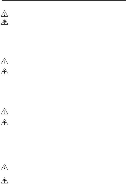
Attach the cables. See the instructions beginning on page 2-5.
Laptop
1 |
|
2 |
|
|
|
|
|
INPUTS |
|
|
OUTPUT |
|
AUDIO INPUTS |
AUX/MIX |
OUT |
CONTROL/ |
|
1 |
2 |
L 3 R L 4 R |
MONO L |
R |
POWER |
Projector
NOTE Ground all devices. If you use cable that has a drain wire, tie the drain wire to ground at both ends.
MLS 102 VGA
MLS 102 VGA
|
|
To connect a computer or third |
A |
B |
party control system, see page 2-8. |
12V |
.5A MAX |
External
Power Supply
VCR Unbalanced,
Stereo Input
A B C D E A B C D E |
1A 1B 2A 2B 3A 3B A B C D |
||
IR |
RS-232 |
|
|
Display/Source Control |
Relays |
IR/RCM |
|
Wireless |
Balanced/Unbalanced, |
Microphone's |
Mono Aux. Input |
Receiver |
Balanced/ |
|
|
|
Unbalanced |
|
Output |
|
Amplifier |
Extron Switcher Control |
A01-644-33 01 07 theinPrinted USA |
|
1 2 3 4 5 6 |
A B |
|
Tally Out |
MLS/Power |
|
MLC 206
Bottom Panel
AUX/MIX
MONO
For the Aux/Mix Mono audio input, connect a 3.5 mm, 3-pole captive screw connector to one end of an audio cable as shown at right. This line level input can be balanced or unbalanced. Wire the other end to one tip-ring-sleeve connector.
The Aux/Mix level must be adjusted (-43dB to +24dB) via the front panel control. It cannot be adjusted via software.
Tip (+)
Gnd (Sleeve,  )
)
Ring (–)
Aux/Mix Input Wiring
(balanced/unbalanced, mono)
MLS 100 Series• Quick Start Guide QS-1
Quick Start Guide — MLS 100 Series, cont’d
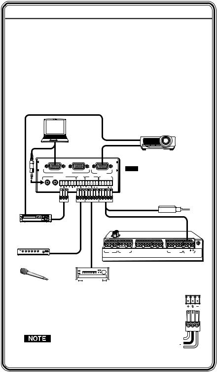
To connect an MLC 206 or a third party control system, see the diagram below, and see page 2-8 for details.
POWER |
MLS100Series |
|
Switcher |
A B |
Control/Power |
Port |
NOTE You must connect a ground wire between the MLC and MLS.
+12VDC input  Ground (
 )
)
External
Power Supply (12VDC, 1A max.)
+12VDC Ground ( )
)
B Receive (Rx)  Transmit (Tx) B
A Transmit (Tx) 
 Receive (Rx) A
NOTE If you use cable that has a drain wire, tie the drain wire to ground at both ends.
|
MLC 206's |
|
MLS/Power |
Step 4 |
Port |
A B |
Connect power cords and turn the equipment on. MLS /Power
Step 5
Test the system: select an input from the front panel buttons or via the control software; observe the display and listen to
the audio output. If you use the MediaLink Control Software, set the volume control in the Controller (MLC) Config section to “Switcher”, as shown at right. Make any needed cabling corrections.


 To avoid damage to your hearing, the Aux/Mix input and the selectable audio inputs’ levels and output volume should be set as low as possible before you test the sound system.
Step 6
Adjust the Aux/Mix level: turn the front panel potentiometer while listening to the audio
output. See page 3-3.
Step 7
Set up the switcher. In the Switcher (MLS) Config part of the MediaLink Control Software, set the perinput audio adjustments, RGB delay period (MLS 102 VGA), and the output volume. See pages 4-8 to 4-10.
Table of Contents
|
Chapter 1 • Introduction .......................................................... |
1-1 |
|
|
About this Manual ................................................................ |
1-2 |
|
|
About the MLS 100 Series Switchers .......................... |
1-2 |
|
|
Features ...................................................................................... |
1-2 |
|
|
Chapter 2 • Installation ............................................................. |
2-1 |
|
|
UL/Safety Requirements ..................................................... |
2-2 |
|
|
Mounting the Switchers .................................................... |
2-2 |
|
|
|
Tabletop use ........................................................................... |
2-2 |
|
|
Rack mounting ....................................................................... |
2-2 |
|
|
Furniture or projector mounting .......................................... |
2-4 |
|
|
For furniture mounting ......................................................... |
2-4 |
|
|
For projector mounting ......................................................... |
2-4 |
|
Rear Panel Features and Cabling .................................. |
2-5 |
|
|
|
Video connections ................................................................. |
2-5 |
|
|
Audio connections ................................................................. |
2-6 |
|
|
Control and power connections ........................................... |
2-8 |
|
Setting Up Optimal Audio Gain ..................................... |
2-9 |
|
|
|
Setup via the MediaLink Control Software ....................... |
2-10 |
|
Application Diagrams ....................................................... |
2-11 |
|
|
Chapter 3 • Operation ................................................................ |
3-1 |
|
|
Front Panel Features and Operation ........................... |
3-2 |
|
|
|
Executive mode — enabling and disabling |
|
|
|
front panel buttons ............................................................... |
3-3 |
|
Troubleshooting ..................................................................... |
3-4 |
|
|
Chapter 4 • Serial Communication ................................... |
4-1 |
|
|
RS-232 Programmer’s Guide ............................................ |
4-2 |
|
s |
|
Host.-to-MLS communication .............................................. |
4-2 |
s |
. |
MLS-initiated message ....................................................... |
4-2 |
. |
s |
Error response ...................................................................... |
4-3 |
|
|
Using the command/response.. table ................................. |
4-3 |
|
|
Command/response table for SIS commands ....................... |
4-4 |
|
|
Command/response table for |
|
|
|
special function SIS commands ............................................. |
4-6 |
|
Control Software for Windows® ................................... |
4-7 |
|
|
|
Installing the software .......................................................... |
4-7 |
QS-2 MLS 100 Series • Quick Start Guide |
MediaLink VersaTools Switchers • Table of Contents |
i |

Table of Contents, cont’d
Using the control program ................................................... |
4-7 |
User Mode .............................................................................. |
4-8 |
Switcher (MLS) Config ......................................................... |
4-10 |
Saving and restoring configurations .................................. |
4-10 |
Emulation mode .................................................................. |
4-11 |
Using the help program ...................................................... |
4-12 |
Key to file names ................................................................. |
4-12 |
Appendix A • Specifications, Part Numbers, |
|
and Accessories.............................................................................. |
A-1 |
Specifications ......................................................................... |
A-2 |
Included Parts ......................................................................... |
A-6 |
Accessories ............................................................................... |
A-7 |
Cables ......................................................................................... |
A-7 |
Adapters .................................................................................... |
A-7 |
MLS 100 Series Switcher Block Diagram .................. |
A-8 |
All trademarks mentioned in this manual are the properties of their respective owners.
68-652-01 Rev. A
Printed in the USA
03 03

 MediaLink™ VersaTools™ Switchers
Chapter1One
Introduction
About this Manual
About the MLS 100 Series Switchers
Features
ii MediaLink VersaTools Switchers • Table of Contents

Introduction
About this Manual
This manual contains information about the Extron MLS 100 Series Switchers (MLS 100 A, MLS 103 V, MLS 103 SV,
MLS 102 VGA) and on how to install, set up, and operate them. “MLS 100 Series switcher”, “MLS”, and “switcher” will be used interchangeably in this manual.
About the MLS 100 Series Switchers
The Extron MLS 100 Series Switchers are compact, quarter rack width switchers. The MLS 102 VGA, MLS 103 SV, and
MLS 103 V have a 250 MHz (-3dB) video bandwidth. The MLS 102 VGA, MLS 103 SV, and MLS 103 V provide a way to switch up to three video input signals (up to two for the VGA model) to one output.
All models (MLS 102 VGA, MLS 103 SV, MLS 103 V, MLS 100 A) feature four selectable audio inputs, and also one Aux/Mix input that is always active and can be mixed with any and all of the four selectable audio inputs.
Front panel buttons, an RS-232-based control system, or an Extron MediaLink™ Controller (MLC) can be used for input selection.
Features
Furniture, rack, and projector mountability — MLS 100 Series Switchers can be mounted under a desk or other furniture, or mounted on a projector lift with optional brackets. Alternatively, they can be rack mounted on an optional rack shelf.
Stereo audio input and output — Unbalanced stereo audio inputs can be output as balanced or unbalanced stereo audio, and the audio output level can be adjusted.
Mono auxiliary/mix audio input— The Aux/Mix port on each switcher lets you mix a mono, line level audio input signal with that of one of the four selectable stereo audio inputs.

 MediaLink™ VersaTools™ Switchers
Chapter2Two
Installation
UL/Safety Requirements
Mounting the Switchers
Rear Panel Features and Cabling
Setting Up Optimal Audio Gain
Application Diagrams
1-2 MediaLink VersaTools Switchers • Introduction
Installation
UL/Safety Requirements
The Underwriters Laboratories (UL) requirements listed below pertain to the safe installation and operation of the switcher.
1.This unit is not to be connected to a centralized DC power source or used beyond its rated voltage range.
The Extron P/S 100 and other Extron power supplies may be used with the MLS.
2.Do not use the switcher near water.
To reduce the risk of fire or electric shock, do not expose this apparatus to rain or moisture.
3.Clean the switcher only with a dry cloth.
4.Do not install the switcher near any heat source, such as a radiator, heat register, stove, or another apparatus (including amplifiers) that produces heat.
5.Unplug the switcher during lightning storms or when it will be unused for long periods.
6.This unit must be installed in accordance with the National Electrical Code.
Mounting the Switchers
The one rack unit high, quarter rack width switchers can be set on a table, or mounted on a rack shelf, mounted under a desk or tabletop, or mounted on a projector bracket.
Tabletop use
Each MLS switcher comes with rubber feet. For tabletop use, attach a self-adhesive rubber foot to each corner of the bottom of the unit.
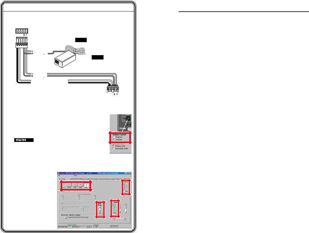
Rack mounting
For optional rack mounting, do not install the rubber feet. Mount the MLS on a VersaTools™ 19" 1U Rack Shelf (Extron part #60-190-20) or a standard Universal 1U Rack Shelf (Extron part #60-190-01). On the standard rack shelf, the MLS mounts in one of four locations to the rear of the rack or in one of four locations to the front of the rack.
1. |
If rubber feet were previously installed on the bottom of |
|
the MLS, remove them. |
2. |
Mount the MLS on the rack shelf, using two 4-40 x 1/8 |
|
screws in opposite (diagonal) corners to secure the MLS |
|
switcher to the shelf. |
Versa Tools Rack Shelf
Quarter Rack Width False Front
Face Plate
Use 2 mounting holes on |
Med |
|
|
opposite corners. |
iaLink |
Sw |
itcher |
|
|
|
|
|
|
|
(2) 4-40 x 3/16" Screws |
Mounting the MLS on a VersaTools rack shelf
Only products in the VersaTools line can be mounted to a VersaTools shelf. Most 1U rack-mountable Extron products can be mounted on the standard shelf.
MLS |
100 |
|
|
|
|
Series |
|
|
|
|
|
|
|
|
|
|
1 |
INPUT |
|
|
|
|
SELE |
CT |
|
|
|
2 |
3
|
AUX |
/MIX |
|
|
|
|
|
4 |
LE |
|
|
|
|
|
|
|
VEL |
|
|
|
|
|
|
MediaLink |
|
|
MLS |
100 |
Series |
|
|
|
Switcher |
|
|
1 |
INPUT |
|
|
|
|
|
|
|
|
SELEC |
T |
|
|
|
|
|
|
2 |
|
3
|
AUX |
4 |
LE /MIX |
|
VEL |
MediaLink |
Switcher |
|
Mounting the MLS on a 1U standard rack shelf
3. |
Install blank panel(s) or other unit(s) to the rack shelf. |
2-2 |
MediaLink VersaTools Switchers • Installation |
MediaLink VersaTools Switchers • Installation |
2-3 |

Installation, cont’d
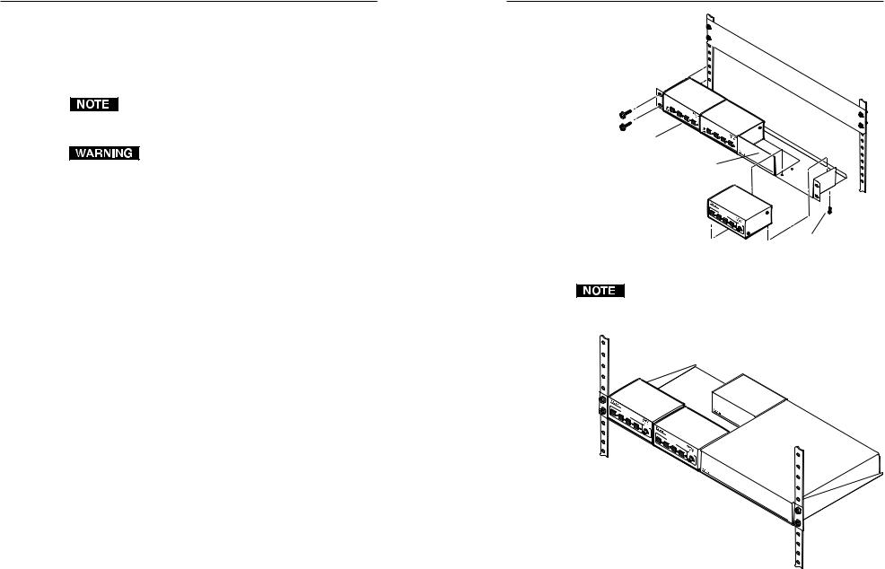
Furniture or projector mounting
Furniture mount or projector mount the MLS using the optional mounting kit (part #70-212-01, furniture; or 70-217-01, projector) as follows:
1. |
Attach the mounting brackets to the MLS with the |
|
machine screws provided. |
2. |
If feet were previously installed on the bottom of the MLS, |
|
remove them. |
For furniture mounting
3a. Hold the MLS with the attached brackets against the underside of the table or other furniture. Mark the location of the screw holes of the bracket on the mounting surface.
4a. Drill 3/32” (2 mm) diameter pilot holes, 1/4” (6.3 mm) deep in the mounting surface at the marked screw locations.
5a. Insert #8 wood screws into the four pilot holes. Tighten each screw into the mounting surface until just less than 1/4” of the screw protrudes.
6a. Align the mounting screws with the slots in the brackets
and place the MLS against the surface, with
the screws through the bracket slots. See the illustration at left.
Mounting the MLS to furniture |
|
Projector |
|
|
|
|
Mounting |
7a. |
Slide the switcher slightly forward or |
Bracket |
|
|
|||
|
back, then tighten all four screws to |
Mounting |
|
|
secure the MLS in place. |
|
Bolt |
|
|
|
|
For projector mounting |
|
|
|
3b. |
Secure the MLS to a projector |
Ceiling |
|
|
mount or other surface by |
|
|
|
|
|
|
|
inserting the mounting bolt |
|
|
|
through the bracket’s slotted |
|
|
|
hole, as shown at right. |
|
|
|
|
|
Digital Projector |
Mounting the MLS to a projector mount
Rear Panel Features and Cabling
Turn off and disconnect power from all the equipment before you connect cables to the MLS.
|
1 |
|
2 |
MLS 102 VGA |
|
|
|
1 |
2 |
|
|
INPUTS |
|
OUTPUT |
|
AUDIO INPUTS |
AUX/MIX |
OUT |
MLC/RS-232 |
1 2 L 3 R |
L 4 R MONO |
L R |
POWER |
|
|
|
|
A B |
MLS 102 VGA |
|
|
12V |
.5A MAX |
7 |
8 |
9 |
10 |
11 |
5 6
MLS 103 V |
1 |
2 |
3 |
|
|
|
|
INPUTS |
|
|
OUTPUT |
|
|
AUDIO INPUTS |
AUX/MIX |
|
OUT |
MLC/RS-232 |
L 1 R L |
2 R L 3 R L |
4 R MONO |
L |
R |
POWER |
A B |
MLS 103 V |
12V |
.5A MAX |
8 9 10 11
|
|
|
3 |
|
|
|
|
4 |
|
MLS 103 SV |
|
|
|
|
|
|
|
||
|
1 |
2 |
|
|
3 |
|
|
|
|
|
|
|
INPUTS |
|
|
|
|
OUTPUT |
|
|
|
AUDIO INPUTS |
|
|
AUX/MIX |
|
OUT |
MLC/RS-232 |
|
L 1 |
R |
L 2 R L 3 |
R L |
4 |
R |
MONO |
L |
R |
POWER |
A B |
MLS 103 SV |
|
12V |
.5A MAX |
8 |
9 |
10 |
11 |
MLS 100 A
AUDIO INPUTS |
AUX/MIX |
OUT |
|
MLC/RS-232 |
L 1 R L 2 R L 3 R L 4 R |
MONO |
L |
R |
POWER |
A B |
MLS 100 A |
|
12V |
.5A MAX |
8 |
9 |
10 |
11 |
Video connections
1Computer video inputs (MLS 102 VGA only) — Cable one or two VGA-UXGA computers to these individually buffered 15-pin HD connectors. These inputs provide ID bit termination.
2Computer video output (MLS 102 VGA only) — Connect a cable from this 15-pin HD connector to the input port of the projector or display.
3S-video inputs (MLS 103 SV only) — Cable up to three S-video sources to the MLS via these female 4-pin mini DIN connectors.
4S-video output (MLS 103 SV only) — Connect the S-video input port of the projector or display to the MLS by plugging S- video cables into these female 4-pin mini DIN connectors.
5Composite video inputs (MLS 103 V only) — Connect up to three composite video input sources to the MLS 103 V using coaxial cables and these female BNCs.
6Composite video output (MLS 103 V only) — Attach a coaxial cable to this female BNC, and connect the other end of the cable to the projector’s or display’s video input port.
2-4 |
MediaLink VersaTools Switchers • Installation |
MediaLink VersaTools Switchers • Installation |
2-5 |
Loading...