


Exmark M3213KC, M3613KC, M4815KC, M3614KA, M4814KA User Manual
...
!
 W A R N IN G
FAILURE TO FOLLOW CAUTIOUS
OPERATING PRACTICES CAN RESULT IN
SERIOUS OPERATOR INJURY.
!CAUTION
1.Keep all shields, guards and safety devices (especially grass discharge system) in place and in proper working condition.
2.Stop engine and remove spark plug wire(s) or remove
key before adjusting, servicing, or performing maintenance.
3.When mower deck becomes clogged, stop engine and remove spark plug wire(s) or remove key before cleaning blockage.
4.Keep hands, feet, and clothing away from power driven parts.
5.Keep off mower unless seat platform is provided.
6.Keep others off mower.
!WARNING
The engine exhaust from this product contains chemicals known to the State of California to cause cancer, birth defects, or other reproductive harm.
! HEALTH WARNING
GASOLINE
Harmful or fatal if swallowed. Long-term exposure to vapors has caused cancer in laboratory animals.
.Avoid prolonged breathing of vapors.
.Keep face away from nozzle and gas tank/container opening.
.Keep away from eyes and skin.
.Never siphon by mouth.
Failure to use caution may cause serious injury or illness.
IMPORTANT
When mower is used or operated on any California forest, brush or grass covered land, a working order spark arrester must be attached to muffler. If not, the operator is violating state law, Section 442 Public Resource Code. To acquire a spark arrester for your unit, see your Engine Service Dealer.
Exmark reserves the right to make changes or add improvements to its products at any time without incurring any obligation to make such changes to products manufactured previously. Exmark, or its distributors and dealers, accept no responsibility for variations which may be evident in the actual specifications of its products and the statements and descriptions contained in this publication.
i

EXMARK PARTS PLUS PROGRAM
EFFECTIVE DATE: September 1, 1995
Program
If your Exmark dealer does not have the Exmark part in stock, Exmark will get the parts to the dealer the next business day or the part will be FREE* Guaranteed!!
How the Program Works
1.If dealer does not have part in stock for a "down" unit at the time of request by customer, the dealer contacts his
distributor by 1:00 p.m., local time, and requests Exmark Parts Plus shipment of six (6) line items or less.
2.Distributor ships part(s) to dealer or customer, as requested by dealer, same day, overnight UPS Distributor bills dealer for part and freight charges where applicable.
3.If distributor does not have the part(s) in stock to satisfy Exmark Parts Plus order, he contacts Exmark by 3:00 p.m., central time, with an Exmark Parts Plus order of six (6) line items or less.
4.If order is received by 3:00 p.m. central time, Exmark ships part(s) direct to dealer or customer, as requested by distributor, same day, overnight UPS, Exmark bills the distributor for parts and shipping charges, where applicable.
5.The customer pays for the part and freight if it is shipped under the Exmark Parts Plus and if it arrives in accordance to the program.
6.Who pays for the part and freight if it fails to arrive overnight in accordance to the program?
A.Under any circumstance the customer does not pay.
B.If the part does not arrive overnight due to:
1.The dealer not submitting the Exmark Parts Plus order to his Exmark distributor by 1:00 p.m., the dealer pays for the part and freight.
2.The Distributor being unable to ship the part the same day or not submitting the Exmark Parts Plus order to Exmark by 3:00 p.m., central time, the Distributor pays for the part and freight.
3.Exmark being unable to ship the part and the Exmark parts order is received by 3:00 p.m., central time, Exmark pays for the part and freight.
4.If the part does not arrive overnight due to the shipper (UPS), the shipper pays for the freight and Exmark pays for the part.
The following restrictions apply -- The Exmark Parts Plus Program is available only through participating Exmark Dealers and applies only to orders submitted on this program Monday through Thursday. UPS has initiated a Saturday delivery program to many areas of the continental United States and can be requested for an overnight shipment on Friday to be delivered Saturday. The next day air charge, plus the Saturday delivery fee will be the responsibility of the purchaser. Exmark Mfg. will assume no responsibility for Saturday delivery shipments. To qualify, all Exmark Parts Plus orders must be received by Exmark by 3:00 p.m., central time. Orders must be six (6) line items or less. Exclusions from the Exmark Parts Plus Program are: Any wholegood or accessory in its entirety, engines and engine replacement parts, 5-speed Peerless transmissions and 5-speed transaxles, hydraulic or hydrostatic wheel motors, cutter decks and engine decks or any item exceeding United Parcel Service size and weight restrictions.
Due to UPS restrictions, aerosol spray paint is considered a hazardous material and cannot be shipped via UPS next day or Second Day Air.
Exmark Manufacturing stocks a limited supply of parts for transaxles, pumps and wheel motors. These parts can be ordered for Next Day Air shipment but will not be guaranteed per the Parts Plus Program.
ii
CONGRATULATIONS on the purchase of your Exmark Mower. This product has been carefully designed and manufactured to give you a maximum amount of dependability and years of trouble-free operation.
OPERATOR'S MANUAL
This manual contains assembly, operating, maintenance, adjustment and safety instructions for your Exmark mower.
BEFORE OPERATING YOUR MOWER, CAREFULLY READ THIS MANUAL IN ITS ENTIRETY.
By following the operating, maintenance and safety instructions, you will prolong the life of your mower, maintain its maximum efficiency and promote safe operation.
If additional information is needed, or should you require trained mechanic service, contact your authorized Exmark equipment dealer or distributor.
All Exmark equipment dealers and distributors are kept informed of the latest methods of servicing and are equipped to provide prompt and efficient service in the field or at their service stations. They carry ample stock of service parts or can secure them promptly for you from the factory.
All Exmark parts are thoroughly tested and inspected before leaving the factory, however, attention is required on your part if you are to obtain the fullest measure of satisfaction and performance.
iii
|
TABLE OF CONTENTS |
|
1. SAFETY |
PAGE |
|
1.1 |
Safety Alert Symbol ............................... |
1 |
1.2 |
Training .......................................... |
1 |
1.3 |
Preparation ..................................... |
1-2 |
1.4 |
Operation ....................................... |
2-3 |
1.5 |
Maintenance & Storage ............................. |
4 |
1.6 |
Riding Attachments ................................ |
4 |
1.7 |
Safety Signs .................................... |
4-6 |
2.SPECIFICATIONS
2.1 |
Model Numbers ..................................... |
6 |
2.2 |
Engine ............................................ |
6 |
2.3 |
Fuel System ....................................... |
6 |
2.4 |
Safety Interlock System ........................... |
7 |
2.5 |
Steering/Brake Control ............................ |
7 |
2.6 |
Transmission ...................................... |
7 |
2.7 |
Wheel Drive System ................................ |
7 |
2.8 |
Tires ............................................. |
7 |
2.9 |
Deck ............................................ |
7-8 |
2.10 |
Dimensions ........................................ |
8 |
2.11 |
Bolt Torque Requirements .......................... |
8 |
3.ASSEMBLY INSTRUCTIONS
3.1 to 3.12 Assembly ................................ |
8-15 |
4.OPERATION INSTRUCTIONS
4.1 |
Controls ...................................... |
15-17 |
4.2 |
Pre-Start ..................................... |
17-18 |
4.3 |
Operating Instructions ........................ |
18-19 |
4.4 |
Transporting ..................................... |
20 |
5.MAINTENANCE & ADJUSTMENTS
5.1 |
Periodic Maintenance .......................... |
20-26 |
5.2 |
Adjustments ................................... |
26-31 |
6.TROUBLE SHOOTING
6.1 |
Mower Tracks Left or Right |
.......................32 |
6.2 |
Mower Cuts Unevenly .............................. |
32 |
6.3 |
Blades Do Not Stop ............................... |
32 |
6.4 |
Engine Will Not Start ......................... |
32 -33 |
7. |
BELT ROUTING (MOWER DECKS) |
.........................33 |
8. |
WIRING DIAGRAMS ..................................... |
34 |
9. |
WARRANTY.......................................... |
35 -36 |
iv

1.SAFETY
1.1SAFETY ALERT SYMBOL
THIS SAFETY ALERT SYMBOL 

 IS USED BOTH IN THIS MANUAL AND ON THE MACHINE TO IDENTIFY IMPORTANT SAFETY MESSAGES WHICH MUST BE FOLLOWED TO AVOID ACCIDENTS. THIS SYMBOL MEANS:
ATTENTION! BECOME ALERT!
YOUR SAFETY IS INVOLVED!
The safety alert symbol appears above information which alerts you of unsafe actions or situations and will be followed by the word DANGER, WARNING, or CAUTION.
When used with the word DANGER: IT DENOTES THAT AN EXTREME HAZARD EXISTS WHICH WOULD RESULT IN HIGH PROBABILITY OF DEATH OR IRREPARABLE INJURY IF PROPER PRECAUTIONS ARE NOT TAKEN.
When used with the word WARNING: IT DENOTES THAT A HAZARD EXISTS WHICH CAN RESULT IN INJURY OR DEATH IF PROPER PRECAUTIONS ARE NOT TAKEN.
When used with the word CAUTION: IT DENOTES A REMINDER OF SAFETY PRACTICES OR DIRECTS ATTENTION TO UNSAFE PRACTICES WHICH COULD RESULT IN PERSONAL INJURY IF PROPER PRECAUTIONS ARE NOT TAKEN.
1.2TRAINING
1.2.1Regard the Exmark mower as a piece of power equipment and teach this regard to all who operate this unit.
1.2.2Read the instructions carefully. Familiarize yourself with the controls and the proper use of the equipment.
1.2.3Never allow children, teenagers, or people unfamiliar with these instructions to use the mower.
1.2.4Avoid mowing while people, especially children or pets, are nearby. Keep in mind that the operator or user is responsible for accidents or hazards occurring to other people or their property.
1.3PREPARATION
1.3.1The use of personal protective equipment, such as (but not limited to) protection for the eyes, ears, feet and head is recommended.
1.3.2While mowing, always wear substantial footwear and long trousers. Do not operate equipment when barefoot or when wearing open sandals.
1.3.3Thoroughly inspect the area where the equipment is to be used and remove all stones, sticks, wires, bones and other foreign objects, which may damage the equipment or cause personal injury to the operator or bystanders.
- 1 -

•Fuel is Highly Flammable. DO NOT smoke while refueling. Refuel only in a well ventilated area, or refuel outdoors.
•Store fuel in containers specifically designed for this purpose.
•Add fuel before starting the engine. Never remove the cap of the fuel tank or add fuel when engine is running or when the engine is hot.
•Never fill the fuel tank so that the fuel level rises above a level that is 1/2” below the bottom of the filler neck to allow for fuel expansion and prevent fuel spillage.
•If fuel is spilled, DO NOT attempt to start the engine. Move away from the area of the spill and avoid creating any source of ignition until fuel vapors have dissipated.
1.4OPERATION
1.4.1Give complete, undivided attention to the job at hand.
1.4.2Mow only in daylight or in good artificial light. DO NOT operate the mower when children or others are in the area.
1.4.3When feasible, avoid operating the equipment in wet grass.
1.4.4Use EXTREME caution when mowing and/or turning on slopes as loss of traction and/or control could occur. Mow across slopes with walk behind mowers, never up and down. Loss of control and/or loss of operator’s footing could result in a fall with an arm or leg getting under the mower or engine deck and sustaining serious injury. Drive slower on slopes. DO NOT operate on slopes greater than 20 degrees. Watch for ditches, holes, rocks, dips, and rises which can cause erratic handlebar movement and loss of footing. Keep away from dropoffs and steep banks. Avoid sudden starts. Look down and behind you before and while moving backwards. DO NOT mow slopes when grass is wet - slippery conditions create hazardous footing, affect steering, and reduce traction and braking. The operator is responsible for safe operation on slopes. See inside back cover to determine the approximate slope angle of the area to be mowed.
1.4.5Stop the blades when crossing surfaces other than grass, if mower must be tilted for transportation, and when transporting the mower to and from the area to be mowed.
1.4.6Never operate the mower with defective guards, shields, or covers. Always have safety shields, guards, switches, and other devices in place and in proper working condition.
1.4.7Do Not change the engine governor settings or overspeed the engine. Operating an engine at excessive speed may increase the hazard of personal injury.
1.4.8Place transmission in neutral, disengage blades, and latch drive levers in “park brake” position before starting engine.
-2 -

1.4.9Start the engine carefully with feet well away from the blades.
1.4.10Keep hands, feet and clothing away from rotating parts while the mower is being operated.
1.4.11Stop the engine and disconnect the spark plug wire(s)and/ or remove key:
a)Before checking, cleaning or working on the mower.
b)After striking a foreign object (inspect the mower for damage and make repairs before restarting and operating the mower).
1.4.12Stop the engine:
a)Before clearing blockages.
b)Before removing the grass catcher.
c)Whenever you leave the mower.
d)Before refueling.
e)Before making height adjustments.
1.4.13Before stopping the engine, return the throttle control to the idle position for 30 seconds to allow the engine to cool down.
1.4.14The fuel system is provided with a shut-off valve. The fuel shut-off valve is used to shut off the fuel when:
a)The machine will not be used for a few days
b)During transport to and from the job
c)When parking inside a building
1.4.15This mower was designed for one operator only. Keep all others away from mower during operation.
1.4.16Do Not mow without the grass deflector or entire grass collection system in place and in proper working condition.
•DO NOT operate the engine in a small confined area where dangerous carbon monoxide fumes can collect.
•Failure to follow safety instructions and cautious operating practices can result in serious injury.
•Although hazard control and accident prevention partially are dependent upon the design and configuration of the equipment, these factors are also dependent upon the awareness, concern, prudence and proper training of the personnel involved in the operation, transport, maintenance and storage of the equipment. It is essential that all Operator Safety Mechanisms be connected and in operating condition prior to use for mowing.
-3 -
1.5MAINTENANCE AND STORAGE
1.5.1For engine maintenance, follow the engine manufacturer's recommendations precisely as stated in the engine manual.
1.5.2If carburetor adjustment is necessary, stand to one
side and keep feet and hands clear while making adjustments.
1.5.3Keep engine and engine area free from accumulation of grass, leaves, excessive grease or oil and other debris which can accumulate in these areas. These materials can become combustible and may result in a fire.
1.5.4Store fuel in a container specifically designed for this purpose. Store the fuel container in a cool, dry place.
1.5.5Keep the mower and fuel container in locked storage to prevent children from playing or tampering with them.
1.5.6Gasoline powered equipment or fuel containers should not be stored in a basement or any enclosed area where open pilot lights or heat appliances are present.
1.5.7Maximum mowing results and safety can only be achieved if the mower is properly maintained and operated correctly.
1.5.8.Check all bolts often to maintain proper tightness.
1.5.9.Keep all guards, shields and all safety devices in place and in safe working condition.
1.5.10Frequently check for worn or damaged components that could create a hazard.
1.5.11All replacement parts must be the same as or equivalent to the parts supplied as original equipment.
1.6RIDING ATTACHMENTS
Use only Exmark riding attachments. The use of other than Exmark riding attachments may create a hazardous condition resulting in injury.
1.7SAFETY SIGNS
1.7.1Keep all safety signs legible. Remove all grease, dirt and debris from safety signs.
1.7.2Safety signs must be replaced if they are missing or illegible.
1.7.3When new components are installed, be sure that current safety signs are affixed to the replaced components.
1.7.4New safety signs may be obtained from your authorized Exmark equipment dealer or distributor or from Exmark Mfg. Co. Inc.
1.7.5Safety signs can be affixed by peeling off the backing to expose the adhesive surface. Apply only to a clean, dry surface. Smooth to remove any air bubbles.
1.7.6Familiarize yourself with the following safety signs and instruction labels. They are critical to the safe operation of your Exmark commercial mower.
-4 -

PART NO. 323688
LOCATION: Console
PART NO. 303508
LOCATION: Right Rear Corner
of Deck
PART NO. 323550
LOCATION: Upper Handles
PART NO. 403005 (Both Sides)
LOCATION: Front Corners
of Deck
PART NO. 303517
LOCATION: Left Side, Rear Surface
Engine Deck |
|
|
8.5 HP B&S |
|
PART NO. 543631 |
|
LOCATION: Upper Handle |
KAWASAKI,KOHLER & 10.5 HP B&S |
Console |
PART NO. 323689 |
|
LOCATION: RH Side of Console |
|
|
- 5 - |
PART NO. 403162
LOCATION: 48” Decks
PART NO. 403143
LOCATION: Right Rear of Engine Deck
PART NO. 303518
LOCATION: Transmission Shifter Plate
2.SPECIFICATIONS
2.1MODEL NUMBER:
Serial No.s 150,000 and Higher
M3213KA; M3613KA; M3613KC; M3614KA; M3615KC; M4814KA; M4815KC.
PART NO. 323427
LOCATION: 32” & 36” Decks
PART NO. 303293
LOCATION: Top Right Side
Fuel Tank
PART NO. 513746 LOCATION: Engine Blower
Housing Next to Muffler
Serial No.s 150,000 –189,999
M329B; M3213KC
Serial No.s 190,000 and Higher
M3211B
2.2ENGINE
2.2.1Engine Specifications: See your engine owner's manual.
2.2.2RPM (No Load): 3600 rpm
2.3FUEL SYSTEM
2.3.1Capacity: 5 gal. (18.9 liter)
2.3.2Type of Fuel: Use only clean, fresh, regular grade, unleaded gasoline with the pump sticker octane rating of 87 or higher. In countries using the research method, it should be 90 octane minimum.
-6 -
2.3.3Fuel Filter: Replaceable in-line
2.3.4Fuel Shut Off Valve: in-line, 1/4 turn
2.4SAFETY INTERLOCK SYSTEM
Operator must have the transmission in neutral and blades disengaged to start engine. Release of Operator Presence Control (OPC) levers will cause engine to stop if transmission is not in neutral and/or blade drive is engaged.
2.5 STEERING/BRAKE CONTROL
Fingertip drive control levers provide independent control of traction, braking and neutral to each drive wheel for moving, stopping & power turning. Parking brakes are engaged by locking drive control levers in the “brake” position.
2.6TRANSMISSION
2.6.1Peerless 700-061, five speeds forward and one reverse.
2.6.2Speed range:
1st |
2.0 |
mph (3.22 |
km/h) |
4th 4.1 |
mph (6.60 |
km/h) |
|||
2nd |
2.7 |
mph |
(4.35 |
km/h) |
5th |
6.2 |
mph |
(9.98 |
km/h) |
3rd |
3.5 |
mph |
(5.63 |
km/h) |
Rev |
3.1 |
mph |
(4.99 |
km/h) |
2.7 WHEEL DRIVE SYSTEM
Banded double A-Section V-belts, single top-side idlers and replaceable bolt-on drive sheaves and brake drums.
(Single B-Section V-belts for the 32" Model)
2.8 TIRES
|
|
Drive |
Front Caster |
||
Size........ |
13 |
x 6.50 - 6 ........... |
9 |
x 3.50 |
- 4 |
(32" Model) . 13 |
x 5.00 - 6 ........... |
9 |
x 3.50 |
- 4 |
|
Quantity........... |
|
2 ...................... |
|
2 |
|
Tread.......... |
|
Turf Saver/Turf Master ..... |
Smooth |
||
Ply................ |
|
4 ...................... |
|
4 |
|
Pressure.... |
14 |
psi (97 kPa).......... |
22 psi (152 kPa) |
||
Bearings.... |
Replaceable Ball ........ |
Replaceable Roller |
|||
2.9DECK
2.9.1Cutting Width:
Model 32 ......31.75 in. (80.7 cm) Model 36 ......35.38 in. (89.9 cm)
Model 48 ......47.63 in. (120.98 cm) S/N 150,000 - 159,999 Model 48 ......47.25 in. (120.0 cm) S/N 160,000 & higher
2.9.2Discharge: Right Side
2.9.3Blade Size:
Model 32 ......16.25 (41.3 cm) - Qty. 2 Model 36 ......18.00 (45.7 cm) - Qty. 2 Model 48 ......16.25 (41.3 cm) - Qty. 3
2.9.4Type of Drive: Manual engagement of belt with overcenter lock. Blade belt tension is adjustable via turnbuckle. The 48 in. units have an additional belt which is also adjustable.
2.9.5Deck Mounting: Bolted directly to engine deck
-7 -
2.9.6Cutting Height: Adjusts in 1/4" (.63 cm) or smaller increments by various adjustments of caster spacers, blade spacers and axle height, from 1” to 4 1/4” (2.5 cm - 10.8 cm).
2.10DIMENSIONS
2.10.1Overall Width:
|
32" |
36" |
48"♦ |
48”◊ |
||||
Discharge chute |
42.45 |
in. |
46.1 |
in. |
58.1 |
in. |
58.2 |
in. |
down |
107.8 cm |
117.1 cm |
147.6 |
cm |
148.0 |
cm |
||
|
|
|
|
|
|
|
|
|
Up |
32.75 |
in. |
36.4 |
in. |
48.4 |
in. |
48.1 |
in. |
(transport only) |
83.2 |
cm |
92.5 |
cm. |
122.9 |
cm |
122.2 |
cm |
|
|
|
|
|
||||
|
32" |
36" |
48"♦ |
48”◊ |
||||
Overall Length |
78 in. |
78 in. |
74.7 |
in. |
73.0 |
in. |
||
|
198.1 cm |
198.1 cm |
189.7 |
cm |
185.4 |
cm |
||
|
|
|
|
|
|
|
|
|
Overall Height |
40.0 in. |
40.0 |
in. |
40.0 |
in. |
40.0 |
in. |
|
|
101.6 cm |
101.6 cm. |
101.6 |
cm |
101.6 |
cm |
||
|
|
|
|
|
|
|
|
|
Tread Width |
32.05 |
in. |
35.6 |
in. |
35.6 |
in. |
35.6 |
in. |
|
81.4 |
cm |
90.4 cm |
90.4 cm |
90.4 cm |
|||
|
|
|
|
|
||||
Curb Weight |
374 lbs |
391 lbs |
431 lbs |
439 lbs |
||||
|
170 kg |
177 |
kg |
196 |
kg |
199 |
kg |
|
|
|
|
|
|
|
|
|
|
To outside of tires.
Weights will vary slightly depending on engine option.
♦ For Serial No.s 150,000 through 159,999.
◊For Serial No.s 160,000 and higher.
2.11TORQUE REQUIREMENTS
BOLT LOCATION |
TORQUE |
|
Blade/Cutter Housing Spindle Bolt ........ |
75-80 |
ft-lbs. |
Caster Bracket Mounts .................... |
30-35 |
ft-lbs. |
Cutter Deck/Engine Deck Mount ............ |
30-35 |
ft-lbs. |
Engine Mounting Bolts |
|
|
Briggs & Stratton ................. |
15-20 |
ft-lbs. |
Kohler & Kawasaki ................. |
25-30 |
ft-lbs. |
Transmission Shifter Lever ............... |
30-35 |
ft-lbs. |
3.ASSEMBLY INSTRUCTIONS
3.1Uncrate unit, leaving it on the pallet, place upper handle assembly, fuel tank, and shifter lever at the rear of the machine. Place casters at the front of the unit.
3.2Place a length of 4" x 4" block between the front of the cutter deck and the pallet.
3.3Remove the bolt bag from the top of the fuel tank support.
3.4Refer to Parts Manual to help you identify and locate parts and their proper position.
-8 -
3.5Install casters to front of deck using appropriate hardware from the bolt bag (eight 3/8 x 3/4" bolts and eight 3/8" whizlock nuts); tightening the lower four bolts first, then the top four.
3.6Loosen the 5/16" hardware at the two (2) discharge deflector hinge points so that the deflector is snug, but can be moved up and down freely.
3.7Mount the fuel tank on the tank support.
Apply retaining adhesive Fel-Pro Pro-Lock ‘Retaining Type I or Retaining II’ or Loctite RC 609 or 680 on the two threaded studs from the bolt bag and install into the two left holes underneath fuel tank. Install the fuel tank on top of the fuel tank support with the studs going through the slots in the support. Install two 5/16 x 3/4 screws with a 5/16” flatwasher and 5/16” lockwasher into the threaded holes in the right side of the fuel tank. Do not over tighten. Place
a 5/16” flatwasher, then a spring, and a 5/16 nyloc nut over each of the studs. Completely tighten nyloc nut then back off a 1/2 turn. This will allow for normal fuel expansion and contraction with changes in temperature and fuel levels.
Do not over tighten.
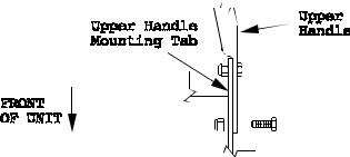
3.8Install Handle Assembly
Position the lower end of the handle assembly on the outside of the upper rear section of the fuel tank & handle support. Install one 3/8-16 x 1" bolt (from the outside in) in the upper hole on each side of the handle.
Loosely secure each screw with a 3/8" nyloc nut. The handle can now be pivoted to allow positioning in one of the three holes allowing various adjustments for operator comfort (See Figures 1 & 2). Once a proper position is found, install one 3/8 x 1" bolt in the bottom mounting holes on each side of the handle. Secure each bolt with a 3/8" nyloc nut. Tighten all hardware.
FIG. 1
UPPER HANDLE MOUNTING
IMPORTANT: If the mower has been completely assembled and the handle position is changed, it will be necessary to readjust the drive and brake linkage.
- 9 -
 Loading...