


User’s Guide
EVGA X58 FTW ³
Motherboard
EVGA X58 FTW3 Motherboard
2
EVGA FTW3 Motherboard
Table of Contents
User’s Guide ................................................................................................................. |
1 |
EVGA X58 FTW ³.......................................................................................................... |
1 |
Motherboard .................................................................................................................. |
1 |
Before You Begin… ...................................................................................................... |
8 |
Parts NOT in the Kit.............................................................................................................. |
9 |
Intentions of the Kit............................................................................................................... |
9 |
Motherboard ................................................................................................................ |
10 |
Motherboard Specifications ................................................................................................ |
10 |
Unpacking and Parts Descriptions ............................................................................. |
12 |
Unpacking ........................................................................................................................... |
12 |
Equipment ........................................................................................................................... |
12 |
EVGA X58 FTW3 Motherboard......................................................................................... |
14 |
Hardware Installation .................................................................................................. |
17 |
Safety Instructions............................................................................................................... |
17 |
Preparing the Motherboard.................................................................................................. |
18 |
Installing the CPU........................................................................................................... |
18 |
Installing the CPU Fan.................................................................................................... |
19 |
Installing System Memory (DIMMs) ............................................................................. |
20 |
Installing the Motherboard .................................................................................................. |
21 |
Installing the I/O Shield .................................................................................................. |
21 |
Securing the Motherboard into a System Case ............................................................... |
22 |
Connecting Cables............................................................................................................... |
22 |
24-pin ATX Power (PW1).......................................................................................... |
23 |
3
EVGA X58 FTW3 Motherboard
8-pin ATX 12V Power (PW12) .................................................................................. |
24 |
Connecting IDE Hard Disk Drives ................................................................................. |
24 |
Connecting SATA Cables............................................................................................... |
25 |
Connecting Internal Headers........................................................................................... |
26 |
Front Panel Header ..................................................................................................... |
26 |
IEEE1394a (Firewire) ................................................................................................ |
27 |
USB Headers .............................................................................................................. |
28 |
Audio .......................................................................................................................... |
29 |
Fan Connections ............................................................................................................. |
30 |
COM1 ............................................................................................................................. |
31 |
Expansion Slots............................................................................................................... |
31 |
PCI Slots..................................................................................................................... |
32 |
PCI-E x1 Slots ............................................................................................................ |
32 |
PCI-E x16/x8 Slots ..................................................................................................... |
32 |
Onboard Buttons ................................................................................................................. |
33 |
Clear CMOS Button ................................................................................................... |
33 |
RESET and POWER Button ...................................................................................... |
33 |
Post Port Debug LED and LED Status Indicators ............................................................... |
34 |
Post Port Debug LED ................................................................................................. |
34 |
LED Status Indicators................................................................................................. |
34 |
Configuring the BIOS .................................................................................................. |
35 |
Enter BIOS Setup ................................................................................................................ |
36 |
Main Menu .......................................................................................................................... |
36 |
Standard CMOS Features Menu.......................................................................................... |
39 |
Date and Time................................................................................................................. |
40 |
SATA Channel................................................................................................................ |
40 |
Halt On............................................................................................................................ |
42 |
Memory........................................................................................................................... |
42 |
4 |
|
EVGA FTW3 Motherboard
Advanced BIOS Features .................................................................................................... |
43 |
Hard Disk Boot Priority .................................................................................................. |
44 |
CD-ROM Device Priority ............................................................................................... |
44 |
First/Second/Third Boot Device ..................................................................................... |
44 |
Boot Other Device .......................................................................................................... |
45 |
Boot Up NumLock Status ............................................................................................... |
45 |
Security Option ............................................................................................................... |
45 |
Integrated Peripherals Menu ............................................................................................... |
46 |
Legacy Devices............................................................................................................... |
46 |
OnChip PATA/SATA Device......................................................................................... |
47 |
Onboard Device .............................................................................................................. |
48 |
USB Device Settings ...................................................................................................... |
49 |
Power Management Setup Menu ........................................................................................ |
50 |
ACPI Function ................................................................................................................ |
50 |
ACPI Suspend Type........................................................................................................ |
51 |
Run VGABIOS if S3 Resume......................................................................................... |
51 |
Soft-Off by PWR-BTTN................................................................................................. |
51 |
Wake-Up by PCI Card .................................................................................................... |
51 |
USB KB Wake-Up From S3........................................................................................... |
51 |
Resume by Alarm ........................................................................................................... |
51 |
POWER ON Function .................................................................................................... |
52 |
Hot Key Power On.......................................................................................................... |
52 |
PWRON after PWR-Fail................................................................................................. |
52 |
PnP/PCI Configuration Menu ............................................................................................. |
53 |
Init Display First ............................................................................................................. |
53 |
Reset Configuration Data................................................................................................ |
54 |
Resources Controlled By ................................................................................................ |
54 |
IRQ Resources ................................................................................................................ |
54 |
5
EVGA X58 FTW3 Motherboard
PCI/VGA Palette Snoop ................................................................................................. |
55 |
INT Pin 1/2/3/4/5/6/7/8 Assignment............................................................................... |
55 |
Maximum Payload Size .................................................................................................. |
55 |
PC Health Status Menu ....................................................................................................... |
56 |
SmartFan Function.......................................................................................................... |
57 |
Frequency/Voltage Control Menu....................................................................................... |
58 |
Memory Feature.............................................................................................................. |
59 |
Voltage Control............................................................................................................... |
61 |
CPU Feature.................................................................................................................... |
63 |
Installing Drivers and Software .................................................................................. |
65 |
Windows XP/Vista/Win 7 Driver Installation..................................................................... |
65 |
Appendix A. POST Codes........................................................................................... |
67 |
EVGA Glossary of Terms............................................................................................ |
74 |
Compliance Information .............................................................................................. |
77 |
6
EVGA FTW3 Motherboard
List of Figures
Figure 1. |
EVGA X58 FTW3 Motherboard Layout ........................................................... |
14 |
Figure 2. |
Chassis Back Panel Connectors ......................................................................... |
16 |
Figure 3. |
PW1 Motherboard Connector ............................................................................ |
23 |
Figure 4. |
BIOS CMOS Setup Utility Main Menu ............................................................. |
37 |
Figure 5. |
Standard CMOS Features Menu ........................................................................ |
39 |
Figure 6. |
Advanced BIOS Features Menu ........................................................................ |
43 |
Figure 7. |
Integrated Peripherals Menu .............................................................................. |
46 |
Figure 8. |
Power Management Setup Menu ....................................................................... |
50 |
Figure 9. |
PnP/PCI Configuration Menu ............................................................................ |
53 |
Figure 10. |
PC Health Status Menu ................................................................................. |
56 |
Figure 11. |
Frequency/Voltage Control Menu ................................................................. |
58 |
Figure 12. |
Memory Feature Menu .................................................................................. |
59 |
Figure 13. |
Voltage Control ............................................................................................. |
61 |
Figure 14. |
CPU Feature Menu ........................................................................................ |
63 |
7
EVGA X58 FTW3 Motherboard
Before You Begin…
Thank you for purchasing the EVGA X58 FTW3 Motherboard. This board is designed to take the already excellent performance of the EVGA lineup and push it into the future by adding support for SATA 6Gbps and USB 3.0. Also we have included EVBot support to facilitate your tweaking needs.
As always with this board you also get the added bonus of EVGA’s industry leading 24/7 technical support in case you ever have any issues or questions.
8

EVGA FTW3 Motherboard
Parts NOT in the Kit
This kit contains all the hardware necessary to install and connect your new EVGA X58 FTW3 Motherboard. However, it does not contain the following items that must be purchased separately to make the motherboard functional.
Intel Microprocessor
System Memory
Cooling fan for the Microprocessor
Graphics Card
Power Supply
EVGA assumes you have purchased all the necessary parts needed to allow for proper system functionality.
Intentions of the Kit
This kit provides you with the motherboard and all connecting cables necessary to install the motherboard into a system case. If you are building a PC, you will use most of the cables provided in the kit. If however, you are replacing a motherboard, you will not need many of the cables.
When replacing a motherboard in a system case, you will need to reinstall an operating system even though the current Hard Disk Drive may already have an operating system.
9

EVGA X58 FTW3 Motherboard
EVGA X58 FTW ³
Motherboard
Thank you for purchasing the EVGA X58 FTW3 Motherboard. This motherboard offers enthusiast performance and when combined with two or three SLI-Ready NVIDIA® GeForce® graphics cards, you get innovative NVIDIA® SLI® technology for enhanced system performance.
Motherboard Specifications
Size
ATX form factor of 12 inch x 9.6 inch
Microprocessor support Intel Core i7 processor
Operating systems:
Supports Windows XP, Windows Vista and Win 7 32 and 64 bit
Contains Intel X58 and ICH10R chipset
System Memory support
Supports triple channel DDR3-1600+. Officially supports up to 24GBs of DDR3 memory.
USB 2.0 Ports Supports hot plug
Twelve USB 2.0 ports (Eight rear panel ports, four onboard USB headers) Supports wake-up from S1 and S3 mode
Supports USB 2.0 protocol up to a 480 Mbps transmission rate
USB 3.0 Ports
Two USB 3.0 ports (on I/O panel.)
Backwards compatible USB 2.0 and USB 3.0 support.
Supports transfer speeds up to 4.8Gbps
10
EVGA FTW3 Motherboard
Six(6) onboard SATA II Ports + 2 onboard SATA3 ports 300MBps data transfer rate
Six SATA II connectors from south bridge with support for RAID 0, RAID 1, RAID 0+1, and RAID 5
Two (2) SATA3 600MBps onboard ports from Marvell 88SE9128 Chipset
Onboard LAN
Integrated Dual LAN ports
Supports 10/100/1000 Mbit/sec Ethernet
Onboard IEEE1394a (Firewire) Support hot plug
Two IEEE1394a ports (one rear panel port, one onboard header) with a rate transmission of 400 Mbps
Onboard Audio
Realtek High-Definition audio Supports 8-channel audio Supports Jack-Sensing function
Triple PCI-E Support Three (3) PCI-E 2.0 Slots
Supports 4 GB/sec (8 GB/sec concurrent) bandwidth Low power consumption and power management features
Green Function
Supports ACPI (Advanced Configuration and Power Interface) Supports S0 (normal), S1 (power on suspend), S3 (suspend to RAM), S4
(Suspend to disk - depends on OS), and S5 (soft - off)
Expansion Slots Two PCI slots One PCI-E x1 slot
Three PCI-E x8/x16 slots
11
EVGA X58 FTW3 Motherboard
Unpacking and
Parts Descriptions
Unpacking
The EVGA X58 FTW3 Motherboard comes with all the necessary cables for adding a motherboard to a system case. If replacing a motherboard, you may not need many of these cables.
All parts shipped in this kit are RoHS-compliant (lead-free) parts.
Equipment
The following accessories are included with the EVGA X58 FTW3 Motherboard.
The EVGA X58 FTW3 Motherboard
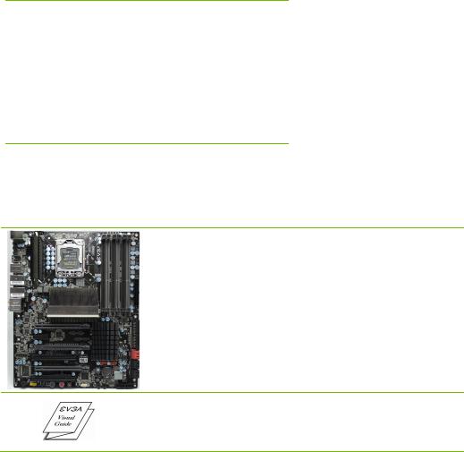
This PCI-E motherboard contains the Intel X58 and ICH10R chipset and is SLI-ready for both 2-Way and 3-Way SLI configurations.
1 - Visual Guide
Helps to quickly and visually guide you through the hardware installation of the motherboard.
12
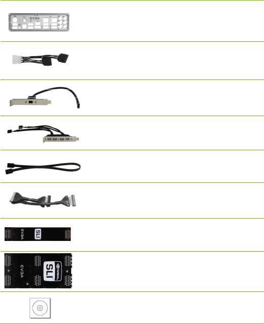
EVGA FTW3 Motherboard
1 - I/O Shield
Installs in the system case to block radio frequency transmissions, protect internal components from dust, foreign objects, and aids in proper airflow within the chassis.
3 - 2-Port SATA Power Cables
Allows a Molex power connector to adapt to a SATA power connector.
1 - IEEE1394a (Firewire) Bracket
Provides one (1) additional IEEE1394a port to the back panel of the chassis.
1 - 4-Port USB 2.0 Bracket
Provides four additional USB ports to either the front or back panels of the chassis.
6 - SATA Data Cables
Used to support the SATA protocol and each one connects a single drive to the motherboard.
1 - IDE Data Cable
Passes data between the IDE connection on the motherboard and IDE device.
1 - 2-Way SLI Bridge
Bridges two (2) graphic cards together which allows for 2-Way SLI.
1 - 3-Way SLI Bridge
Bridges three (3) graphic cards together which allows for 3-Way SLI.
1 - Installation CD
Contains drivers and software needed to setup the motherboard.
13

EVGA X58 FTW3 Motherboard
EVGA X58 FTW3
Motherboard
The EVGA X58 FTW3 Motherboard with the Intel X58 and ICH10R chipset is a PCI-E, SLI-ready motherboard. Figure 1 shows the motherboard and Figures 2 shows the back panel connectors.
14

17
16
15
14
13
12
11
25
4
4
10
8
18 |
|
18 |
|
|
|
|
20 |
|
19 |
21 |
|
|
19 |
19 |
|
|
|
EVGA FTW3 Motherboard
22
24
23
1
2
3
|
9 |
8 |
26 |
|
|
|
4 |
5 |
|
4 |
|
|
7 |
6 |
|
||||||
|
|
|
|
|
|
|
|
|||
|
|
|
|
|
|
|
|
|
|
|
1. |
CPU Socket 1366 |
|
|
|
|
11. |
IEEE1394a Connector |
|
21. |
Front Panel Audio Connector |
|
|
|
|
|
|
|
|
|
|
|
2. |
Intel X58 Chipset |
|
|
|
|
12. |
USB Headers |
|
22. |
Back Panel Connectors (Figure 2) |
|
|
|
|
|
|
|
|
|
|
|
3. |
DDR3 DIMM Slots 1 – 6 |
|
|
|
13. |
Clear CMOS Button |
|
23. |
CPU Fan Connector |
|
|
|
|
|
|
|
|
|
|
|
|
4. |
Fan Connectors |
|
|
|
|
14. |
Power Button |
|
24. |
8-pin ATX_12V Power Connector |
|
|
|
|
|
|
|
|
|
||
5. |
24-Pin ATX Power Connector |
|
|
15. |
Reset Button |
|
25. |
Motherboard Battery |
||
|
|
|
|
|
|
|
|
|
|
|
6. |
IDE Connector |
|
|
|
|
16. |
Serial Connector |
|
26. |
SATA3 600MBps Ports |
7. |
Intel ICH10R Chipset |
|
|
|
17. |
PC Speaker |
|
|
|
|
|
|
|
|
|
|
|
|
|
||
8. |
Serial-ATA (SATA) Connectors |
|
|
18. |
PCI slots |
|
|
|
||
|
|
|
|
|
|
|
|
|
||
9. |
Debug LED Display - CPU Temperature |
|
|
19. |
PCI-E 2.0 Slots |
|
|
|
||
|
Monitor |
|
|
|
|
|
|
|
|
|
10. |
Front Panel Connector |
|
|
|
20. |
PCI-E x1 Slot |
|
|
|
|
Figure 1. EVGA X58 FTW3 Motherboard Layout
15
EVGA X58 FTW3 Motherboard |
|
|
1 |
7 |
7 |
|
||
|
6 |
|
4 |
|
|
2 |
3 |
5 |
2 |
2 |
2 |
8 |
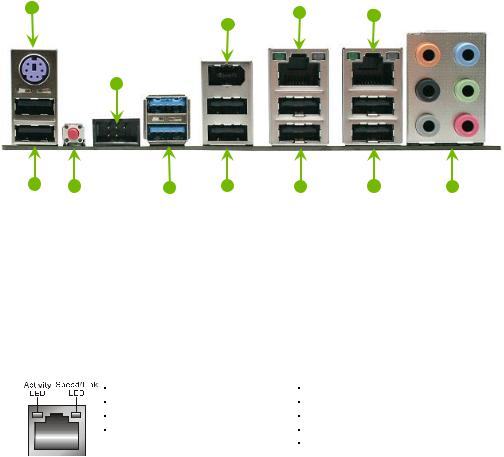
1.PS/2 Keyboard Port
2.USB 2.0 Ports (Eight)
3.Clear CMOS Button
4.EVBot Connector
5.USB 3.0 ports (two)
6.IEE1394a (Firewire) Port
7.Dual LAN Ports with LEDs to indicate status:
Activity LED Status |
Description |
|
|
Off |
No data transmission |
|
|
Blinking (Green) |
Data transmission |
Speed/Link LED Status |
Description |
|
|
Yellow |
1000 Mbps data rate |
|
|
Green |
100 Mbps data rate |
Off |
10 Mbps data rate |
8. Audio Port |
2-Channel |
6-Channel |
8-Channel________ |
|
|
Blue |
Line-In |
Line-In |
Line-In |
|
Green |
Line-Out |
Front Speaker Out |
Front Speaker Out |
|
Pink |
Mic In |
Mic In |
Mic In |
|
Orange |
|
Center/Subwoofer |
Center/Subwoofer |
|
Black |
|
Rear Speaker Out |
Rear Speaker Out |
|
Grey |
|
|
Side Speaker Out |
Figure 2. Chassis Back Panel Connectors
16

EVGA FTW3 Motherboard
Hardware Installation
This section will guide you through the installation of the motherboard. The topics covered in this section are:
Preparing the motherboard Installing the CPU Installing the CPU fan Installing the memory
Installing the motherboard
Connecting cables
Safety Instructions
To reduce the risk of fire, electric shock, and injury, always follow basic safety precautions.
Remember to remove power from your computer by disconnecting the AC main source before removing or installing any equipment from/to the computer chassis.
17
EVGA X58 FTW3 Motherboard
Preparing the Motherboard
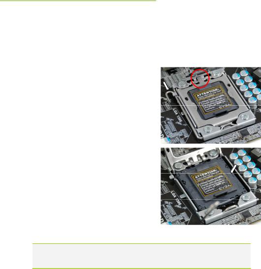
Installing the CPU
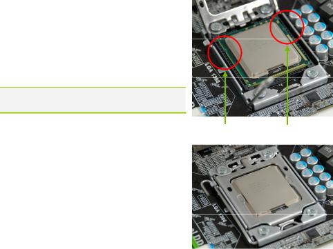
Be very careful when handling the CPU. Hold the processor only by the edges and do not touch the bottom of the processor.
Use the following procedure to install the
CPU onto the motherboard:
Unhook the socket lever by pushing down and away from the socket.
Put your finger on the tail of the load plate and press down with light pressure to lift the load plate up.
Lift the load plate. There is a protective socket cover within the CPU socket to protect the socket when there is no CPU installed.
Remove the protective socket cover from the
CPU Socket.
Note: After removing the CPU socket cover, it is recommended that you keep it in case you need to remove CPU for any reason you can replace the cover to avoid damaging the CPU socket pins.
18
EVGA FTW3 Motherboard
Align the notches in the processor with the notches on the socket.
Lower the processor straight down into the socket with out tilting or sliding it into the socket
Note: Make sure the CPU is fully seated and level in the socket.
Close the load plate over the CPU and press down while you close and engage the socket lever.
The CPU installation is complete.
Align notches with notches on the CPU
Installing the CPU Fan
There are many different fan types that can be used with this motherboard. Follow the instruction that came with you fan assembly. Be sure that the fan orientation is correct for your chassis type and your fan assembly.
19
EVGA X58 FTW3 Motherboard
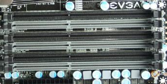
Installing System Memory (DIMMs)
Your new motherboard has six 240-pin slots for DDR3 memory. These slots support 1GB, 2GB, 4GB DDR3 technologies. There must be at least one memory bank populated to ensure normal operation. Use the following the recommendations for installing memory. (See Figure 1 on page 15 for the location of the memory slots.)
One DIMM: If using 1 DIMM (Single Channel), install into: DIMM slot 1.
Two or Four DIMMs: If using 2 DIMMs (Dual Channel), install into: DIMM slots 1 and 3. If using 4 DIMMs (Dual Channel), install into:
DIMM slots 2, 1, 4, and 3.
Three DIMMs: If using 3 DIMMs (Triple Channel), install into: DIMM slots 1, 3 and 5.
Six DIMMs: If using more than 4 DIMMs, use: DIMM slots 2, 1, 4, and 3 then proceed to occupy the following DIMM slots in this order: 5 and 6.
 DIMM Slot 2
 DIMM Slot 1
 DIMM Slot 4
 DIMM Slot 3
 DIMM Slot 6
 DIMM Slot 5
Use the following procedure to install DIMMs. Note that there is only one gap near the center of the DIMM slot. This slot matches the slot on the DIMM to ensure the component is installed properly.
1.Unlock a DIMM slot by pressing the module clips outward.
Align the memory module to the DIMM slot, and insert the module vertically into the DIMM slot. The plastic clips at both sides of the DIMM slot automatically lock the DIMM into the connector.
20
EVGA FTW3 Motherboard
Installing the Motherboard
The sequence of installing the motherboard into a system case depends on the chassis you are using and if you are replacing an existing motherboard or working with an empty system case. Determine if it would be easier to make all the connections prior to this step or to secure the motherboard and then make all the connections. It is normally easier to secure the motherboard first.
Use the following procedure to install the I/O shield and secure the motherboard into the chassis.
Note: Be sure that the CPU fan assembly has enough clearance for the system case covers to lock into place and for the expansion cards. Also make sure the CPU Fan assembly is aligned with the vents on the covers. This will depend on the system case being used.
Installing the I/O Shield
The motherboard kit comes with an I/O shield that is used to block radio frequency transmissions, protects internal components from dust and foreign objects, and promotes correct airflow within the chassis.
Before installing the motherboard, install the I/O shield from the inside of the chassis. Press the I/O shield into place and make sure it fits securely. If the I/O shield does not fit into the chassis, you would need to obtain the proper size from the chassis supplier.
21

EVGA X58 FTW3 Motherboard
Securing the Motherboard into a System Case
Most system cases have a base with mounting studs or spacers to allow the motherboard to be secured to the chassis and help to prevent short circuits. If there are studs that do not align with a mounting hole on the motherboard, it is recommended that you remove that stud to prevent the possibility of a short circuit. In most cases, it is recommended to secure the motherboard using a minimum of nine (9) spacers and screws.
1.Carefully place the motherboard onto the stand off /spacers located inside the chassis.
Align the mounting holes with the studs/spacers.
Align the connectors to the I/O shield.
Ensure that the fan assembly is aligned with the chassis vents according to the fan assembly instruction.
Secure the motherboard with a recommended minimum of nine (9) screws.
Connecting Cables
This section takes you through all the necessary connections on the motherboard. This will include:
Power Connections 24-pin ATX power (PW1)
8-pin ATX 12V power (PW12)
Internal Headers Front panel IEEE 1394a USB Headers Audio
COM
IDE
SATA II
SATA 3
22
EVGA FTW3 Motherboard
Chassis Fans
USB 2.0
USB 3.0
Expansion slots
CMOS Clear Button
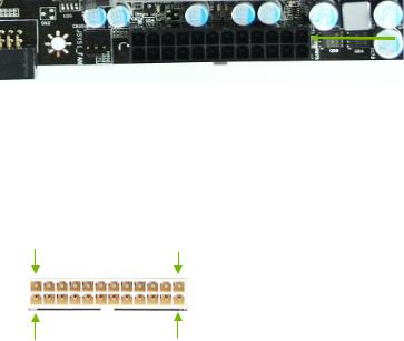
24-pin ATX Power (PW1)
PW1 is the main power supply connector located along the edge of the board next to the DIMM slots. Make sure that the power supply cable and pins are properly aligned with the connector on the motherboard. Firmly plug the power supply cable into the connector and make sure it is secure.
PW1 connector
Plug power cable from system power supply to PW1
Card edge
Figure 3. PW1 Motherboard Connector
Table 1. PW1 Pin Assignments
Connector |
|
|
Pin |
|
|
Signal |
Pin |
|
|
Signal |
|
|
|
|
|
|
|
|
|
|
|
|
|
|
1 |
|
|
+3.3V |
13 |
|
|
+3.3V |
1 |
12 |
|
|
|
|
|
|
|
|
|
|
2 |
|
|
+3.3V |
14 |
|
|
-12V |
||
|
|
|
|
|
|
|||||
|
|
|
|
|
|
|
||||
|
|
|
|
|
|
|
|
|
|
|
|
|
|
3 |
|
|
GND |
15 |
|
|
GND |
|
|
|
|
|
|
|
|
|
|
|
|
|
|
4 |
|
|
+5V |
16 |
|
|
PS_ON |
|
|
|
|
|
|
|
|
|
|
|
|
|
|
5 |
|
|
GND |
17 |
|
|
GND |
|
|
|
|
|
|
|
|
|
|
|
13 |
24 |
|
6 |
|
|
+5V |
18 |
|
|
GND |
|
|
|
|
|
|
|
|
|
||
|
7 |
|
|
GND |
19 |
|
|
GND |
||
|
|
|
|
|
|
|
||||
|
|
|
|
|
|
|
|
|
|
|
|
|
|
8 |
|
|
PWROK |
20 |
|
|
RSVD |
|
|
|
|
|
|
|
|
|
|
|
|
|
|
9 |
|
|
+5V_AUX |
21 |
|
|
+5V |
|
|
|
|
|
|
|
|
|
|
|
|
|
|
10 |
|
|
+12V |
22 |
|
|
+5V |
|
|
|
|
|
|
|
|
|
|
|
|
|
|
11 |
|
|
+12V |
23 |
|
|
+5V |
|
|
|
|
|
|
|
|
|
|
|
|
|
|
12 |
|
|
+3.3V |
24 |
|
|
GND |
|
|
|
|
|
|
|
|
|
|
|
23
EVGA X58 FTW3 Motherboard
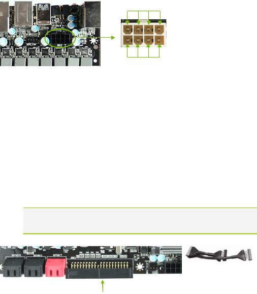
8-pin ATX 12V Power (PW12)
PW12, the 8-pin ATX 12V power connection, is used to provide power to the CPU. Align the pins to the connector and press firmly until seated.
GND
12V
Connecting IDE Hard Disk Drives
The IDE connector supports Ultra ATA 133/100 IDE hard disk drives.
1.Connect the blue connector (the cable end with a single connector) to the motherboard.
2.Connect the black connector (the cable with the two closely spaced black and gray connectors) to the Ultra ATA master device.
3.Connect the grey connector to a slave device.
If you install two hard disk drives, you must configure the second drive as a slave device by setting its jumper accordingly. Refer to the hard disk documentation for the jumper settings.
Note: If an ATA-100 disk drive and a disk drive using any other IDE transfer protocol are attached to the same cable, the maximum transfer rate between the drives may be reduced to that of the slowest drive.
Motherboard Edge
IDE Connector
24
 Loading...