


User Guide
EVGA Classified
Super Record 2 (SR-2)
Dual Xeon
Motherboard
2
EVGA Classified SR-2 Motherboard
Table of Contents
Before You Begin… ............................................................................................... |
8 |
Parts NOT in the Kit........................................................................................... |
9 |
Intentions of the Kit .......................................................................................... |
9 |
EVGA Classified Super Record 2 (SR-2) Motherboard............................................ |
10 |
Motherboard Specifications .............................................................................. |
10 |
Unpacking and Parts Descriptions ....................................................................... |
12 |
Unpacking....................................................................................................... |
12 |
Equipment ...................................................................................................... |
12 |
EVGA Classified SR-2 Motherboard ................................................................... |
14 |
Hardware Installation .......................................................................................... |
18 |
Safety Instructions .......................................................................................... |
18 |
Preparing the Motherboard .............................................................................. |
19 |
Installing the CPU ........................................................................................ |
19 |
Installing the CPU Fan.................................................................................. |
20 |
Installing DIMMs.......................................................................................... |
21 |
Installing the Motherboard ............................................................................... |
22 |
Installing the I/O Shield ............................................................................... |
22 |
Securing the Motherboard into the Chassis.................................................... |
23 |
Connecting Cables and Setting Switches ........................................................... |
24 |
Power Connections ...................................................................................... |
24 |
24-pin ATX Power (PW1) .......................................................................... |
24 |
8-pin ATX 12V Power (PW12-P0-1, PW12-P1-1) ......................................... |
25 |
3
Connecting IDE Hard Disk Drives .................................................................. |
26 |
Connecting Serial ATA Cables ....................................................................... |
27 |
Connecting Internal Headers ........................................................................ |
28 |
Front Panel Header .................................................................................. |
28 |
USB Headers ........................................................................................... |
29 |
Audio Header........................................................................................... |
30 |
Fan Connections .......................................................................................... |
31 |
Expansion Slots ........................................................................................... |
32 |
PCI-E x16 Slots ........................................................................................ |
33 |
Onboard Buttons ............................................................................................. |
35 |
Clear CMOS Button .................................................................................. |
35 |
RESET and POWER Button…………………………………………………………………….35 |
|
Post Port Debug LED and LED Status Indicators ................................................ |
36 |
Post Port Debug LED ................................................................................ |
36 |
LED Status Indicators ............................................................................... |
36 |
Jumper Settings .............................................................................................. |
37 |
PCI-E Disable Jumper ............................................................................... |
37 |
Voltage Measure Point ..................................................................................... |
38 |
EVGA Control Panel (ECP) ................................................................................ |
39 |
Configuring the BIOS .......................................................................................... |
47 |
Enter BIOS Setup ............................................................................................ |
48 |
Main Menu...................................................................................................... |
49 |
Standard BIOS FeaturesMenu……………………………………………………………………….51 |
|
System Time/SystemDate…………………………………………………………………………52 |
|
Advanced BIOS Features ................................................................................. |
53 |
SATA Configuration…………………………………………………………………………………..54 |
|
AHCI Configuration…………………………………………………………………………………..54 |
|
4
EVGA Classified SR-2 Motherboard
E-SATA Controller (Back panel)………………………………………………………………….54 SATA Configuration………………………………………………………………………………………….55 Advanced Chipset Features………………………………………………………………………………56 USB Configuration……………………………………………………………………………………56 PCI-E Configuration………………………………………………………………………………….56 PCI/PNP Resource Management……………………………………………………………………….58 Clear NVRAM…………………………………………………………………………………………..58 Plug & Play O/S……………………………………………………………………………………….58 PCI Latency Timer……………………………………………………………………………………58 Allocate IRQ to PCI VGA……………………………………………………………………………59 Pallette Snooping……………………………………………………………………………………..59 PCI IDE Busmaster…………………………………………………………………………………..59 Offboard PCI/ISA IDE Card……………………………………………………………………….59 Boot Configuration Features…………………………………………………………………………60 Boot Settings Configuration………………………………………………………………………60 Boot Device Priority………………………………………………………………………………….60 Hard Disk Drives………………………………………………………………………………………60 Power Management Features……………………………………………………………………….61 ACPI Configuration…………………………………………………………………………………..61 Hardware Health Configuration…………………………………………………………………….62 H/W HealthFunction…………………………………………………………………………………62 CPU Fan Mode Setting………………………………………………………………………………62 Frequency/Voltage Control…………………………………………………………………………..62 CPU Configuration……………………………………………………………………………………63 Memory Configuration………………………………………………………………………………63 Voltage Configuration……………………………………………………………………………….64 Signal Tweaks………………………………………………………………………………………….64
5
CPU Frequency Setting……………………………………………………………………………..64 |
|
CPU Multiplier Setting……………………………………………………………………………….64 |
|
QPI Frequency…………………………………………………………………………………………64 |
|
Memory Frequency…………………………………………………………………………………..65 |
|
Installing Drivers and Software ........................................................................... |
66 |
Windows XP/Vista/Win7 Drivers Install ............................................................. |
66 |
Appendix A. POST Codes ..................................................................................... |
67 |
EVGA Glossary of Terms ...................................................................................... |
69 |
6
EVGA Classified SR-2 Motherboard
List of Figures
Figure 1. |
EVGA Classified SR-2 Motherboard Layout .......................................... |
15 |
Figure 2. |
Chassis Back panel Connectors .......................................................... |
16 |
Figure 3. |
Power Supply Connectors .................................................................. |
24 |
Figure 4. |
Standard BIOS Features Menu………………………………………………………..51 |
|
Figure 5. |
Advanced BIOS Features Menu .......................................................... |
53 |
Figure 6. |
SATA Configuration………………………………………………………………………..55 |
|
Figure 7. |
Advanced Chipset Features…………………………………………………………….56 |
|
Figure 8. |
PCI/PNP Resource Management……………………………………………………..58 |
|
Figure 9. |
Boot Configuration Features……………………………………………………………60 |
|
Figure 10. |
Power Management Features………………………………………………………….61 |
|
Figure 11. |
H/W Health Configuration……………………………………………………………….62 |
|
Figure 12. |
Frequency/Voltage Control……………………………………………………………..63 |
|
7
Before You Begin…
Thank you for purchasing the EVGA Super Record 2 (SR-2) Motherboard. This is the premier dual socket enthusiast class motherboard.
With this purchase you not only receive the best dual Xeon motherboard built for the enthusiast, by the enthusiast, you also receive industry leading 24/7 technical support. If you ever have any issues we are here to support you and your purchase for the life of the product.
8

EVGA Classified SR-2 Motherboard
Parts NOT in the Kit
This kit contains all the hardware necessary to install and connect your new EVGA Classified SR-2 motherboard. However, it does not contain the following items that must be purchased separately to make the motherboard functional.
1 or 2 Intel 1366 Xeon Dual QPI microprocessors:
Cooling fan for each microprocessor
System memory support
Graphics Card
Power Supply
EVGA assumes you have purchased all the necessary parts needed to allow for proper system functionality.
Intentions of the Kit
This kit provides you with the motherboard and all connecting cables necessary to install the motherboard into a PC case. If you are building a PC, you will use most of the cables provided in the kit. If however, you are replacing a motherboard, you will not need many of the cables.
When replacing a motherboard in a PC case, you will need to reinstall an operating system even if the current drives have an operating system already.
9

EVGA Classified Super Record (SR-2)
Dual Xeon Motherboard
Motherboard Specifications
Size
HPTX (High Performance Technology Extended) form factor of 15 inches x
13.6inches
Microprocessor support
Intel 1366 Xeon Dual QPI Microprocessor
Operating systems:
Supports Windows XP 32bit/64bit , Windows Vista 32bit/64bit or Windows 7 32bit and 64bit (64bit Recommended)
Contains Intel 5520 and ICH10R chipset
System Memory support
Supports triple channel DDR3-1600+ (Overclocked). Supports up to 48GBs DDR3 (ECC or Non ECC memory).
USB 2.0 Ports Supports hot plug
Ten USB 2.0 ports (six back panel ports, four onboard USB headers) Supports wake-up from S1 and S3 mode
Supports USB 2.0 protocol up to 480 Mbps transmission rate Two USB 3.0 ports (Rear panel)
Backwards compatible USB 2.0 and USB 3.0 support. Supports up to 4.8Gbps transmission rate
10
EVGA Classified SR-2 Motherboard
Six(6) onboard Serial ATA II 300MBps data transfer rate
Six SATA II connectors from south bridge ICH10R with support for RAID 0, RAID 1, RAID 10, and RAID 5
Two (2) SATA II connectors from JMicron JMB362 (two rear panel port for E-SATA,)
Two (2) SATA3 600MBps onboard connectors from Marvell 9128 Chipset
Onboard LAN
Dual LAN interface built-in onboard marvell 88E8057 chipset. Supports 10/100/1000 Mbit/sec Ethernet
Onboard Audio
Realtek High-Definition audio Realtek Chipset ALC889 Supports 8-channel audio Supports S/PDIF output Supports Jack-Sensing function
PCI-E Support
Seven (7) PCI-E 2.0 Slots
Supports 4 GB/sec (8 GB/sec concurrent) bandwidth Low power consumption and power management features
Green Function
Supports ACPI (Advanced Configuration and Power Interface)
Supports S0 (normal), S1 (power on suspend), S3 (suspend to RAM), S4 (Suspend to disk - depends on OS), and S5 (soft - off)
11
Unpacking and
Parts Descriptions
Unpacking
The EVGA Classified SR-2 motherboard comes with all the necessary cables for adding a motherboard to a new chassis. If you are replacing a motherboard, you may not need many of these cables.
Be sure to inspect each piece of equipment shipped in the packing box. If anything is missing or damaged, contact your reseller.
Equipment
The following accessories are included with EVGA Classified - motherboard.
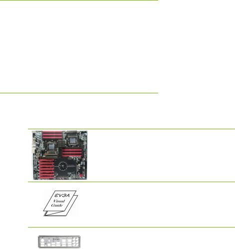
The EVGA Classified SR-2 Motherboard
This motherboard contains the Intel 5520 and ICH10R chipset and is SLI-ready for 2-way, Quad, 3-way, 3-way SLI w/ PhysX and 4-way SLI configurations.
Visual Guide
Helps to quickly and visually guide you through the hardware installation of the motherboard.
I/O Shield
Installs in the system case to block radio frequency transmissions, protect internal components from dust, foreign objects, and aids in proper airflow within the chassis.
12
EVGA Classified SR-2 Motherboard
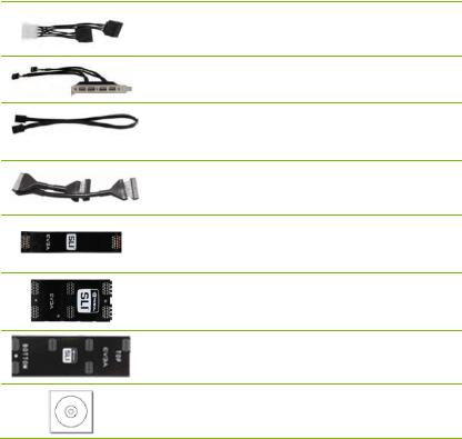
3 - 2-Port SATA Power Cables
Allows a Molex power connector to adapt to a SATA power connector.
1 - 4-Port USB Bracket
Provides one (4) additional USB ports on the rear of the case.
6 - SATA Data Cables
Used to support the Serial ATA protocol and each one connects to a single drive to the motherboard.
1 - IDE-ATA 133 HDD Cable
Passes data between the IDE connection on the motherboard and IDE device.
1 - 2-Way SLI Bridge
Bridges two (2) graphic cards together which allows for 2-Way SLI.
1 – 3-Way SLI Bridge
Bridges three (3) graphic cards together which allows for 3-Way SLI.
1 – 4-Way SLI Bridge
Bridges four (4) graphic cards together which allows for 4-Way SLI. (on select card models)
1 - Installation CD
Contains drivers and software needed to setup the motherboard.
13

EVGA Classified SR-2 Motherboard
The EVGA Classified SR-2 Motherboard with the Intel 5520 and ICH10R chipset is a SLI-ready motherboard. Figure 1 shows the motherboard and Figure 2 shows the back panel connectors.
14

EVGA Classified SR-2 Motherboard
Figure 1. EVGA Classified SR-2 Motherboard Layout
4 |
2 |
1 |
22 |
23 |
|
|
25
22
23
26
21 
20 |
19 18 17 |
7 |
3 |
14 |
5 |
13 12 |
11 |
4
7
16
15
8
6
10
9
1. |
Primary CPU socket |
11. |
P80P connector (ECP V3) |
21. |
PCI-E 2.0 slots |
2. |
Secondary CPU socket |
12. |
Front panel connector |
22. |
8-pin ATX_12V power connector |
3. |
NVIDIA NF200 Chipsets |
13. |
Debug LED Display |
23. |
6 Pin CPU power (optional) |
|
|
|
|
|
|
4. |
CPU Fan headers |
14. |
USB headers |
24. |
Front panel Audio connector |
|
|
|
|
|
|
5. |
Intel 5520 + ICH10R Chipsets |
15. |
CMOS battery |
25. Back panel connectors (Figure 2) |
|
6. |
24-pin ATX power connector |
16. |
EZ voltage read points |
26. |
6 Pin power for PCI-E slots |
7. |
Fan connectors |
17. |
CMOS clear button |
|
|
8. |
PCI-E x16 disable jumpers |
18. |
Power button |
|
|
|
|
|
|
|
|
9. |
IDE connector |
19. |
Reset button |
|
|
|
|
|
|
|
|
10. |
Serial-ATA (SATA) connectors |
20. |
PC Speaker |
|
|
15
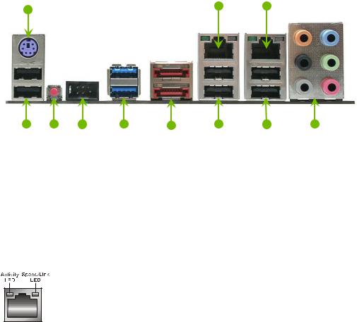
Figure 2. Motherboard I/O Panel Connectors
1 |
7 |
7 |
|
|
2 |
3 |
4 |
5 |
6 |
2 |
2 |
8 |
1.PS/2 Keyboard Port
2.USB 2.0 ports
3.CMOS Clear Button
4.EVBot Connector
5.USB 3.0/2.0 ports (Two)
6.E-SATA ports (Two)
7.Dual Lan Ports with LEDs to indicate status
Activity LED Status |
Description |
|
|
Off |
No data transmission |
|
|
Blinking (Green) |
Data transmission |
|
|
Speed/Link LED Status |
Description |
|
|
Yellow |
1000 Mbps data rate |
|
|
Green |
100 Mbps data rate |
Off |
10 Mbps data rate |
8. Audio Port |
2-Channel |
6-Channel |
8-Channel________ |
|
|
Blue |
Line-In |
Line-In |
Line-In |
|
Green |
Line-Out |
Front Speaker Out |
Front Speaker Out |
|
Pink |
Mic In |
Mic In |
Mic In |
|
Orange |
|
Center/Subwoofer |
Center/Subwoofer |
|
Black |
|
Rear Speaker Out |
Rear Speaker Out |
|
Gray |
|
|
Side Speaker Out |
16

Hardware Installation
This section will guide you through the installation of the motherboard. The topics covered in this section are:
Preparing the motherboard
Installing the CPU’s
Installing the CPU fans
Installing the memory
Installing the motherboard
Connecting cables
Safety Instructions
To reduce the risk of fire, electric shock, and injury, always follow basic safety precautions.
Remember to remove power from your computer by disconnecting the AC main source before removing or installing any equipment from/to the computer chassis.
18
EVGA Classified SR-2 Motherboard
Preparing the Motherboard
The motherboard shipped in the box does not contain a CPU or memory. You need to purchase these to complete the installation.
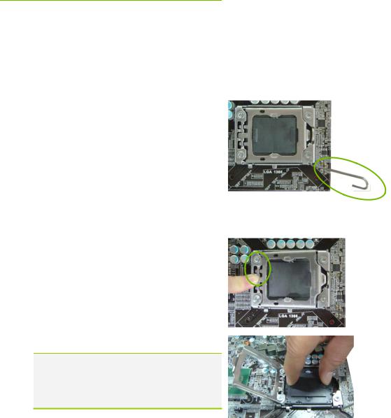
Installing the CPU
Be very careful when handling the CPU. Make sure not to bend or break any pins inside the socket. Hold the processor only by the edges and do not touch the bottom of the processor.
Use the following procedure to install the CPU onto the motherboard.**
**Please ensure that with single processor
usage you are using CPU socket 0 and the adjacent ram bank.
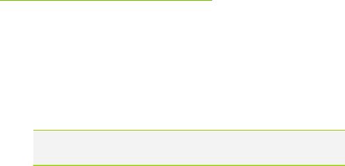
1.Unhook the socket lever by pushing down and away from the socket.
2.Put your finger on the tail of the load plate and press the tail down
3.Lift the load plate. There is a protective socket cover in the socket to protect the socket when there is no CPU installed.
4.Remove the protective socket cover from the CPU Socket.
Remove the processor from its protective cover, making sure you hold it only by the edges. It is a good idea to save the cover so that whenever you remove the CPU, you have a safe place to store it.
19
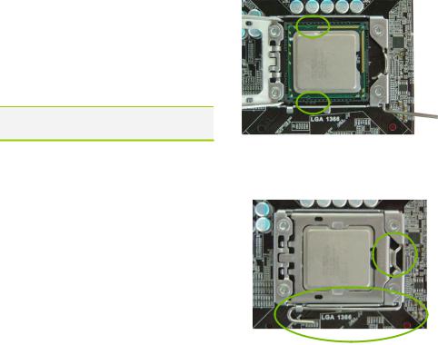
5.Align the notches of the socket with the notches on the cpu.
6.Lower the processor straight down into the socket without tilting or sliding it into the socket
Make sure the CPU is fully seated and level in the socket.
7.Close the load plate over the CPU and
press down while you close and |
Align notches with notches on the CPU |
|
|
engage the socket lever. |
|
8.The CPU installation is complete.
Installing the CPU Fan
There are many different fan types that can be used with this motherboard. Follow the instruction that came with your fan assembly. Be sure that the fan orientation is correct for your chassis type and your fan assembly.
20
EVGA Classified SR-2 Motherboard
Installing DIMMs
Your new motherboard has twelve (12) 240-pin slots for DDR3 DIMMs (ECC or Non ECC). They are arranged in two (2) sets of Six (6) slots each. These slots support 1Gb, 2Gb, and 4Gb DDR3 technology. There must be at least one DIMM slot populated in each bank to ensure normal operation. Use the following recommendations for installing DIMMs. (See Figure 1 on page16 for the location of the DIMM slots.)
One DIMM: If using 1 DIMM (Single Channel), install into: DIMM slot 1.
Two or Four DIMMs: If using 2 DIMMs (Dual Channel), install into: DIMM slots 1 and 3. If using 4 DIMMs (Dual Channel), install into:
DIMM slots 2, 1, 4, and 3.
Three DIMMs: If using 3 DIMMs (Triple Channel), install into: DIMM slots 1, 3 and 5.
Six DIMMs: If using more than 4 DIMMs, use: DIMM slots 2, 1, 4, and 3 then proceed to occupy the following DIMM slots in this order: 6 and 5.
DIMM Slot 2
 DIMM Slot 1
 DIMM Slot 4
 DIMM Slot 3
 DIMM Slot 6
 DIMM Slot 5
Use the following procedure to install DIMMs. Note that there is only one gap near the center of the DIMM slot. This slot matches the slot on the DIMM to ensure the component is installed properly.
1.Unlock a DIMM slot by pressing the module clips outward.
2.Align the memory module to the DIMM slot, and insert the module vertically into the DIMM slot. The plastic clips at both sides of the DIMM slot automatically lock the DIMM into the connector.
21
Installing the Motherboard
The sequence of installing the motherboard into the chassis depends on the chassis you are using and if you are replacing an existing motherboard or working with an empty chassis. Determine if it would be easier to make all the connections prior to this step or to secure the motherboard and then make all the connections. It is normally easier to secure the motherboard first.
Use the following procedure to install the I/O shield and secure the motherboard into the chassis.
Be sure that the CPU fan assembly has enough clearance for the chassis covers to lock into place and for the expansion cards. Also make sure the CPU Fan assembly is aligned with the vents on the covers.
Installing the I/O Shield
The motherboard kit comes with an I/O shield that is used to block radio frequency transmissions, protects internal components from dust and foreign objects, and promotes correct airflow within the chassis.
Before installing the motherboard, install the I/O shield from the inside of the chassis. Press the I/O shield into place and make sure it fits securely. If the I/O shield does not fit into the chassis, you would need to obtain the proper size from the chassis supplier.
22
 Loading...