


Ironguard-1T
Table of contents
 Loading...
EverFocus Ironguard-1T, Ironguard, Ironguard-8T, Ironguard-4T, Ironguard-2T User Manual
...
IRONGUARD 16 POE
16CH H.265 8MP NVR
User’s Manual
Copyright © EverFocus Electronics Corp.
Release Date: July 2019

EVERFOCUS ELECTRONICS CORPORATION
IRONGUARD 16 POE
16CH H.265 8MP NVR
User’s Manual
1995-2019 EverFocus Electronics Corp.
www.everfocus.com.tw
Disclaimer
All the images including product pictures or screen shots in this document are for example only. The
images may vary depending on the product and software version. Information contained in this document
is subject to change without notice.
Copyright
All rights reserved. No part of the contents of this manual may be reproduced or transmitted in any form
or by any means without written permission of the EverFocus Electronics Corporation.
Windows is a registered trademark of the Microsoft Corporation.
D-Link is a registered trademark of the D-Link Corporation.
DynDNS is a registered trademark of the DynDNS.org Corporation.
Other product and company names mentioned herein may be the trademarks of their respective owners.

Safety Precautions
Refer all work related to the installation of this product to qualified service personnel or
system installers.
Do not block the ventilation openings or slots on the cover.
Do not drop metallic parts through slots. This could permanently damage the appliance.
Turn the power off immediately and contact qualified service personnel for service.
Do not attempt to disassemble the appliance. To prevent electric shock, do not remove
screws or covers. There are no user-serviceable parts inside. Contact qualified service
personnel for maintenance. Handle the appliance with care. Do not strike or shake, as this
may damage the appliance.
Do not expose the appliance to water or moisture, nor try to operate it in wet areas. Do
take immediate action if the appliance becomes wet. Turn the power off and refer servicing
to qualified service personnel. Moisture may damage the appliance and also may cause
electric shock.
Do not use strong or abrasive detergents when cleaning the appliance body. Use a dry cloth
to clean the appliance when it is dirty. When the dirt is hard to remove, use a mild
detergent and wipe gently.
Do not overload outlets and extension cords as this may result in a risk of fire or electric
shock.
Do not operate the appliance beyond its specified temperature, humidity or power source
ratings. Do not use the appliance in an extreme environment where high temperature or
high humidity exists. Use the NVR at temperatures within 0°C~40°C / 32°F~104°F (Storage).
The input power source is 12VDC.
Read Instructions
All the safety and operating instructions should be read before the unit is operated.
Retain Instructions
The safety and operating instructions should be retained for future reference.
Heed Warnings
All warnings on the unit and in the operating instructions should be adhered to.
ii

ATTENTION! This is a class A product which may cause radio interference in a domestic
Follow Instructions
All operating and use instructions should be followed.
Cleaning
Unplug the unit from the outlet before cleaning. Do not use liquid cleaners, abrasive or
aerosol cleaners. Use a damp cloth for cleaning.
Attachments
Do not use attachments not recommended by the product manufacturer as they may
cause hazards.
Water and Moisture
Do not use this unit near water-for example, near a bath tub, wash bowl, kitchen sink, or
laundry tub, in a wet basement, near a swimming pool, in an unprotected outdoor
installation, or any area which is classified as a wet location.
Servicing
Do not attempt to service this unit by yourself as opening or removing covers may expose
you to dangerous voltage or other hazards. Refer all servicing to qualified service
personnel.
Power Cord Protection
Power supply cords should be routed so that they are not likely to be walked on or pinched
by items placed upon or against them, playing particular attention to cords and plugs,
convenience receptacles, and the point where they exit from the appliance.
Object and Liquid Entry
Never push objects of any kind into this unit through openings as they may touch
dangerous voltage points or short-out parts that could result in a fire or electric shock.
Never spill liquid of any kind on the unit.
RTC (Real Time Clock) Battery
When encounter failure of time calibration of your NVR, the issue may be caused by
running-out of RTC battery. Users will have to change the RTC battery on the main board
of the NVR.
environment; in this case, the user may be urged to take adequate measures.
iii

This Product is RoHS compliant.
Federal Communication Commission Interference Statement
cause undesired operation.
WEEE
This product complies with the High-Definition Multimedia Interface (HDMI)
This equipment has been tested and found to comply with the limits for a Class B digital
device, pursuant to Part 15 of the FCC Rules. These limits are designed to provide
reasonable protection against harmful interference in a residential installation. This
equipment generates, uses and can radiate radio frequency energy and, if not installed
and used in accordance with the instructions, may cause harmful interference to radio
communications. However, there is no guarantee that interference will not occur in a
particular installation. If this equipment does cause harmful interference to radio or
television reception, which can be determined by turning the equipment off and on, the
user is encouraged to try to correct the interference by one of the following measures:
•Reorient or relocate the receiving antenna.
•Increase the separation between the equipment and receiver.
•Connect the equipment into an outlet on a circuit different from that to which the
receiver is connected.
•Consult the dealer or an experienced radio/TV technician for help.
FCC Caution: Any changes or modifications not expressly approved by the party
responsible for compliance could void the users’ authority to operate this equipment.
This device complies with part 15 of the FCC Rules. Operation is subject to the following
two conditions:
(1) This device may not cause harmful interference, and
(2) This device must accept any interference received, including interference that may
Your EverFocus product is designed and manufactured with high quality materials and
components which can be recycled and reused. This symbol means that electrical and
electronic equipment, at their end-of-life, should be disposed of separately from your
household waste. Please, dispose of this equipment at your local community waste
collection/recycling centre. In the European Union there are separate collection systems
for used electrical and electronic product.
Please, help us to conserve the environment we live in!
Specification Adopter Agreement.
iv

TABLE OF CONTENTS
1. Introduction ............................................................................................................................ 1
1.1 Features .......................................................................................................................... 2
1.2 Dimensions ...................................................................................................................... 2
1.3 Packing List ...................................................................................................................... 2
1.4 Front Panel ...................................................................................................................... 2
1.5 Rear Panel ....................................................................................................................... 3
2. Connection and Installation .................................................................................................... 4
2.1 Hard Disk Installation ...................................................................................................... 4
2.1.1 Hard Disk Compatibility List ........................................................................................ 5
2.2 Basic Connection ............................................................................................................. 6
2.2.1 Terminal Block............................................................................................................. 6
2.3 Accessing the Web Interface .......................................................................................... 7
3. Getting Started ...................................................................................................................... 10
3.1 Turning On / Off the Power .......................................................................................... 11
3.2 Startup Wizard .............................................................................................................. 12
3.3 General Operation on the OSD Menu .......................................................................... 20
3.4 Live View Window ......................................................................................................... 22
3.5 Live Channel Tool Bar .................................................................................................... 24
3.5.1 Digital Zoom (PIP)...................................................................................................... 25
3.5.2 PTZ Control Panel ...................................................................................................... 26
3.5.2.1 PTZ Control Panel ................................................................................................. 26
3.5.2.2 Preset Setting ........................................................................................................ 27
3.6 Live Alarm Panel ............................................................................................................ 29
4. OSD Menu ............................................................................................................................. 34
4.1 Channel ......................................................................................................................... 35
4.1.1 Channel ..................................................................................................................... 35
4.1.1.1 IP Channels ............................................................................................................ 35
4.1.1.1.1 Adding PoE IP Cameras ................................................................................. 37
4.1.1.1.2 Auto Add IP Cameras .................................................................................... 38
4.1.1.1.3 Manually Add IP Cameras ............................................................................. 39
4.1.1.2 Manage Protocol ................................................................................................... 40
4.1.2 Live ............................................................................................................................ 41
4.1.3 Image Control............................................................................................................ 43
4.1.4 PTZ ............................................................................................................................. 45
4.1.5 Privacy Mask ............................................................................................................. 46
4.1.6 Motion....................................................................................................................... 47
4.1.7 Intelligent .................................................................................................................. 48
4.1.7.1 Perimeter Intrusion ............................................................................................... 48
v

4.1.8.1.1 Configuring Perimeter Intrusion Areas ......................................................... 49
4.1.7.2 Line Crossing ......................................................................................................... 50
4.1.8.2.1 Configuring Line Crossing Detection Lines .................................................... 51
4.1.7.3 Foreign/Missing Object ......................................................................................... 52
4.1.8.3.1 Configuring Foreign/Missing Areas ............................................................... 53
4.1.7.4 Pedestrian Detection ............................................................................................ 54
4.1.8.4.1 Configuring Pedestrian Detection Area ........................................................ 55
4.1.7.5 Face Detection ...................................................................................................... 56
4.1.7.5.1 Configuring Face Detection Area .................................................................. 57
4.1.7.5.2 Configuring Face Recognition Settings ......................................................... 58
4.1.7.6 Cross-Counting Detection ..................................................................................... 60
4.1.8.6.1 Configuring Cross-Counting Detection Line .................................................. 61
4.1.7.7 Sound Detection ................................................................................................... 62
4.1.7.8 Tamper Detection ................................................................................................. 63
4.1.7.9 Record Schedule ................................................................................................... 64
4.1.7.10 Cross-Counting Analysis ...................................................................................... 65
4.2 Record ........................................................................................................................... 66
4.2.1 Stream ....................................................................................................................... 66
4.2.1.1 Main Stream .......................................................................................................... 66
4.2.1.2 Sub Stream ............................................................................................................ 68
4.2.1.3 Mobile Stream ...................................................................................................... 69
4.2.2 Record ....................................................................................................................... 70
4.2.2.1 Record ................................................................................................................... 70
4.2.2.2 Record Schedule ................................................................................................... 71
4.2.3 Snapshot ................................................................................................................... 72
4.2.3.1 Snapshot ............................................................................................................... 72
4.2.3.2 Snap. Schedule ...................................................................................................... 73
4.3 Alarm ............................................................................................................................. 74
4.3.1 Motion....................................................................................................................... 74
4.3.2 IO ............................................................................................................................... 76
4.3.3 Intelligent Alarm ....................................................................................................... 78
4.3.3.1 IVS Alarm Settings ................................................................................................. 78
4.3.3.2 Face Recognition Alarm Settings .......................................................................... 80
4.3.3.3 Statistics ................................................................................................................ 85
4.3.4 PTZ Linkage ............................................................................................................... 86
4.3.5 Exception ................................................................................................................... 87
4.3.6 Alarm Schedule ......................................................................................................... 88
4.4 Network ........................................................................................................................ 89
4.4.1 General ...................................................................................................................... 89
vi

4.4.1.1 General .................................................................................................................. 89
4.4.1.2 PPPoE .................................................................................................................... 90
4.4.1.3 Port Configuration ................................................................................................ 91
4.4.2 DDNS ......................................................................................................................... 92
4.4.3 Email .......................................................................................................................... 95
4.4.3.1 Email Configuration .............................................................................................. 95
4.4.3.2 Email Schedule ...................................................................................................... 96
4.4.4 FTP ............................................................................................................................. 97
4.4.4.1 FTP ......................................................................................................................... 97
4.4.4.2 FTP Schedule ......................................................................................................... 98
4.4.5 IP Filter ...................................................................................................................... 99
4.5 Device .......................................................................................................................... 100
4.5.1 Disk .......................................................................................................................... 100
4.5.1.1 Disk ...................................................................................................................... 100
4.5.1.2 Disk Group ........................................................................................................... 102
4.5.1.3 S.M.A.R.T ............................................................................................................. 103
4.5.2 Cloud ....................................................................................................................... 104
4.6 Layout .......................................................................................................................... 106
4.7 Playback ...................................................................................................................... 107
4.7.1 General Operation .................................................................................................. 107
4.7.2 Playback Control Panel ........................................................................................... 108
4.7.2.1 Full Screen on Playback Window ........................................................................ 110
4.7.2.2 Backup Video Clips .............................................................................................. 112
4.7.3 Search Mode ........................................................................................................... 113
4.7.3.1 General ................................................................................................................ 113
4.7.3.2 Events .................................................................................................................. 114
4.7.3.3 Time-Period ......................................................................................................... 118
4.7.3.4 Smart ................................................................................................................... 120
4.7.3.5 Tag ....................................................................................................................... 122
4.7.3.6 External File ......................................................................................................... 124
4.7.3.7 Snapshot ............................................................................................................. 125
4.7.3.8 Intelligent ............................................................................................................ 129
4.8 Express ........................................................................................................................ 130
4.8.1 Quick Playback ........................................................................................................ 130
4.8.2 Stream Switch ......................................................................................................... 130
4.8.3 Preview Policy ......................................................................................................... 130
4.9 System ......................................................................................................................... 131
4.9.1 General .................................................................................................................... 131
4.9.1.1 General ................................................................................................................ 131
vii

4.9.1.2 Date and Time ..................................................................................................... 132
4.9.1.3 Video Output ....................................................................................................... 134
4.9.2 User Account ........................................................................................................... 135
4.9.3 Maintenance ........................................................................................................... 137
4.9.3.1 Log ....................................................................................................................... 137
4.9.3.2 Load Default ........................................................................................................ 139
4.9.3.3 Upgrade............................................................................................................... 139
4.9.3.4 System Parameter ............................................................................................... 140
4.9.3.5 Auto Reboot ........................................................................................................ 140
4.9.4 IPCam Maintain ....................................................................................................... 141
4.9.4.1 Upgrade............................................................................................................... 141
4.9.4.2 Load Default ........................................................................................................ 141
4.9.4.3 Reboot IPC ........................................................................................................... 142
4.9.4.4 System Parameter ............................................................................................... 142
4.9.5 System Info ............................................................................................................. 143
4.9.5.1 System Info ......................................................................................................... 143
4.9.5.1.1 Performing the P2P Function ...................................................................... 143
4.9.5.2 Channel Info ........................................................................................................ 145
4.9.5.3 Record Info .......................................................................................................... 146
4.9.5.4 Network Info ....................................................................................................... 146
4.10 Exit ............................................................................................................................... 147
5. Remote Access to the NVR ................................................................................................. 148
5.1 Accessing the NVR on the Network ............................................................................ 148
5.2 Remote Live View Window ......................................................................................... 151
5.2.1 Camera List .............................................................................................................. 152
5.2.2 Live View Function Icons ......................................................................................... 153
5.2.3 PTZ Setting Panel .................................................................................................... 155
5.2.4 Color Panel .............................................................................................................. 158
5.3 Menu Bar..................................................................................................................... 159
5.3.1 Live .......................................................................................................................... 159
5.3.2 Playback .................................................................................................................. 160
5.3.2.1 Download ............................................................................................................ 163
6. Specification ........................................................................................................................ 164
7. Troubleshooting .................................................................................................................. 166
8. Usage Maintenance ............................................................................................................ 168
Appendix A: IR Remote Control .................................................................................................. 169
Appendix B: Push Notification .................................................................................................... 170
viii
IRONGUARD 16 POE
1
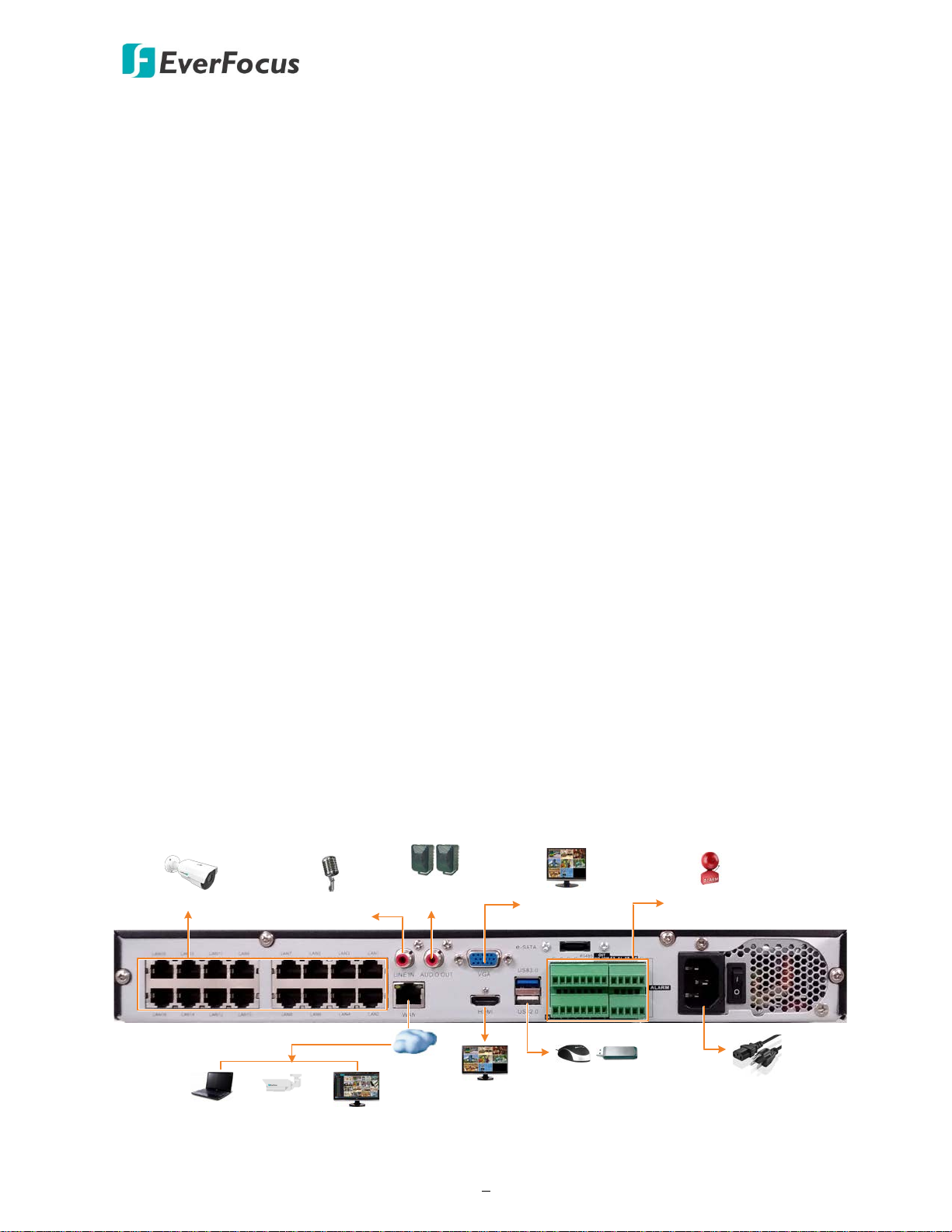
Line Level
Audio Out
Line Level
Audio Input
IP Cameras
Main Monitor
(VGA)
Main Monitor
(HDMI)
Power Cord
Mouse / USB Storage
Web Remote Client
IP Cameras
Network
EverFocus CMS
Alarm In
/ Out
and RS-485
1
Chapter
1. Introduction
EverFocus’ H.265 NVR, IRONGUARD 16 POE, supports 16 channels 8MP (4K) IP cameras. The
model comes with 16 PoE ports (802.3at) for connecting to the IP cameras. A 1Gbps Ethernet port
is also provided for internet connection.
IRONGUARD 16 POE supports AI Face Recognition and IVS functions. Users can utilize the AI
function for access control or use the IVS functions, such as Perimeter Intrusion Detection, Line
Crossing Detection, Object Detection, Pedestrian Detection and Cross-Counting Detection for
security purpose.
Operating on a Linux-based system, the IRONGUARD 16 POE is able to install up to 2 SATA HDDs
with 8TB storage capacity per HDD. Besides, the NVR also supports one e-SATA port for connecting
to the external backup storage. The model also features cloud storage for users to backup
recordings or snapshot images to the FTP sites or Dropbox.
The IRONGUARD 16 POE supports multi-channel playback at multiple speed options and easy data
search by event, snapshot, tags or sub-periods. Users may enable and perform the specified
functions through the local OSD menu or Web interface. Furthermore, you can output the video to
a 4K monitor through HDMI; or use EverFocus’ mobile APP, eFVMS, to remotely view camera
streams from NVR through your handheld devices; or use EverFocus CMS video management
system for remote management.
EverFocus’ IRONGUARD 16 POE NVR is the best choice for a complete IP surveillance solution. It is
versatile, flexible and well catered to the needs of the industry.
IRONGUARD 16 POE
2
•
•
•
•
Front View
Side View
380mm / 14.96"
50mm / 1.97"
340mm / 13.39"
• NVR x 1
• Quick Installation Guide x 1
2
3
1
1.1 Features
Supports 8MP (4K) IP camera up to 16
channels
• Supports 16 PoE ports
• Supports H.265 / H.264 compression format
• Supports 2 HDDs (8TB / HDD)
Supports 1 e-SATA port
Supports ONVIF 2.0 IP cameras
• Supports AI and IVS functions
• Control methods: mouse / IR remote
controller
• Integrates with EverFocus CMS
Supports mobile App: eFVMS App
1.2 Dimensions
1.3 Packing List
• Power Cord x 1
• Mouse x 1
• HDD Screw x 8
Note:
1. Equipment configurations and supplied accessories vary by country. Please consult your
local EverFocus office or agents for more information. Please also keep the shipping carton
for possible future use.
2. Contact the shipper if any items appear to have been damaged in the shipping process.
3. The CD contains the IP Utility software, User Manual and Quick Installation Guide.
4. Risk of explosion if battery is replaced by an incorrect type. Dispose of used batteries
according to the instructions.
a. Use only two AAA dry cell batteries.
b. Do not dispose of the batteries in a fire as it may explode.
• CD x 1 (see Note 3)
• IR Remote Control (with 2 AAA batteries) x 1 (see Note 4)
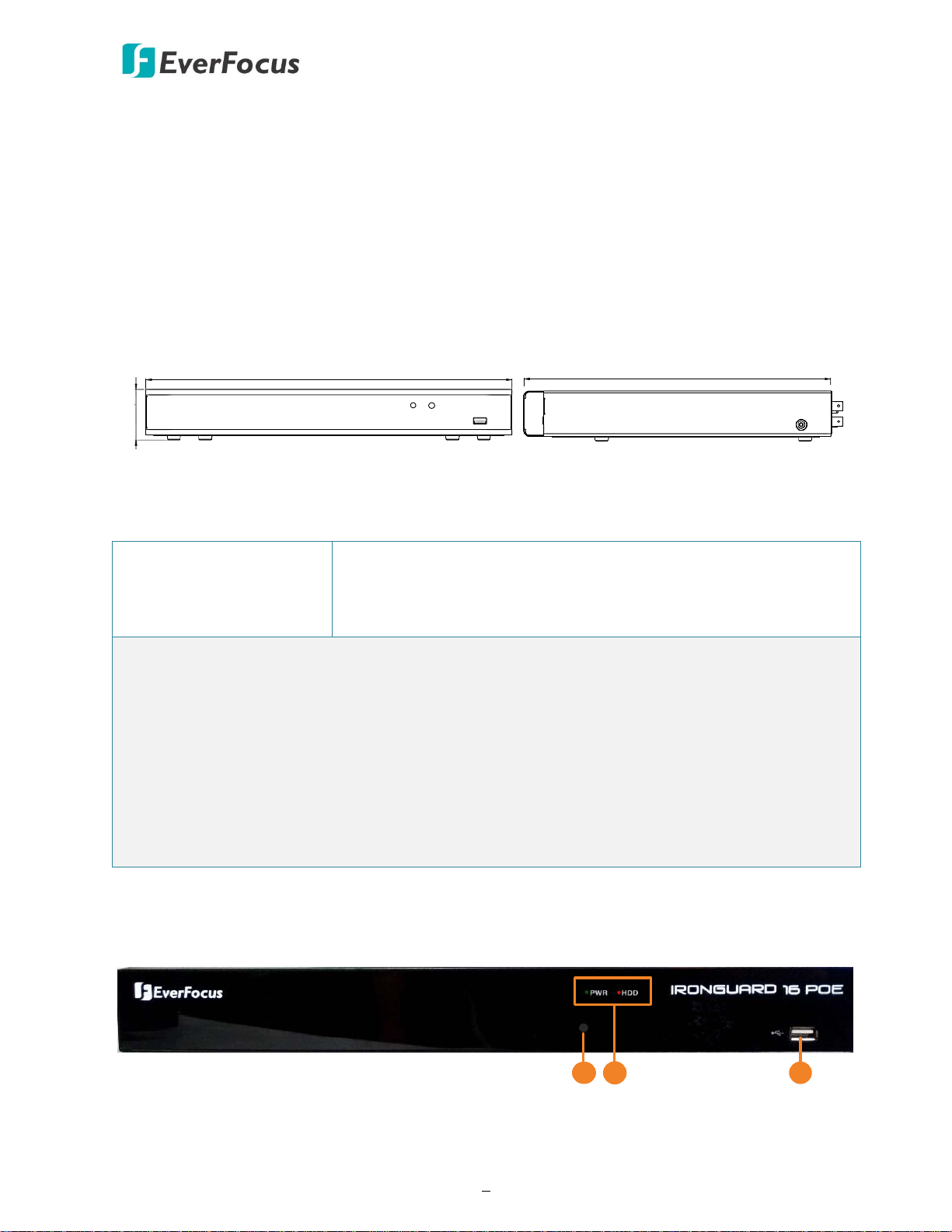
1.4 Front Panel
IRONGUARD 16 POE
3
2
5
1
7
3
6
8
9
10 11
4
Connects to an audio output device, such as speakers. Note that the
required.
No. Name Description
1 IR Receiver
Receiver for signals from the IR remote control. Please refer to
Appendix A. IR Remote Control.
Power: When power is on, the LED will continue lighting in green.
2 LED Indicator
HDD: When power is on, the LED will continue lighting in red. When
HDD is reading/writing data, the LED will flashes red.
3 USB2.0 Port USB2.0 port for connecting to a mouse or an external storage device.
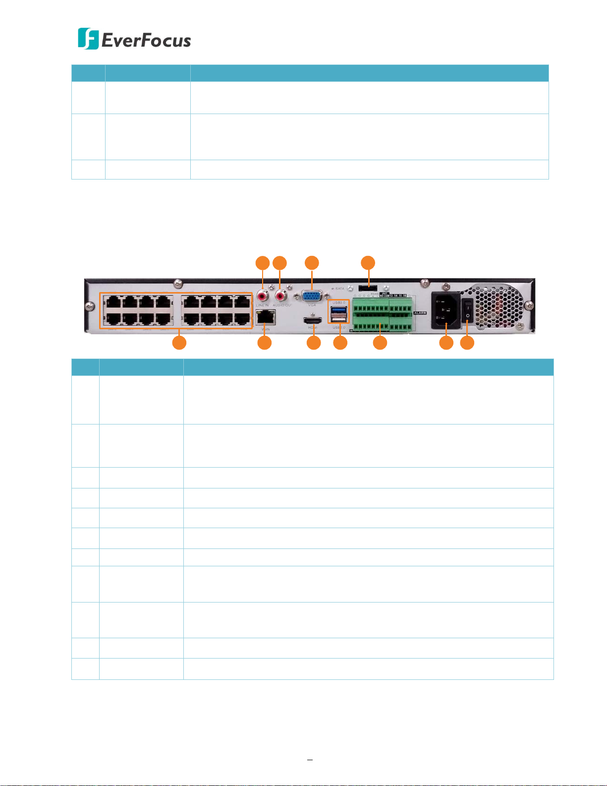
1.5 Rear Panel
No. Name Description
Connects to audio input devices, such as microphones. Note that the
1 Audio Input
microphones with a (built-in) amplifier and external power supply are
required.
2 Audio Output
speakers with a (built-in) amplifier and external power supply are
3 VGA Port Connects to a monitor using a VGA cable.
4 e-SATA Connects to an external e-SATA storage device.
5 Video Input LAN (PoE) ports for connecting to the IP cameras.
6 WAN Connects to the Network.
7 HDMI Port Connects to a monitor using a HDMI cable.
USB2.0 Port
8
USB3.0 Port
9 Terminal Block
USB ports for connecting to a mouse or an external storage device.
The Terminal Block provides alarm inputs, alarm output and RS-485
connection. Please refer to 2.2.1 Terminal Block.
10 Power Port Connects to a 12VDC power source.
11 Power Switch Press to turn on or off the power.
IRONGUARD 16 POE
4
2
Chapter
2. Connection and Installation
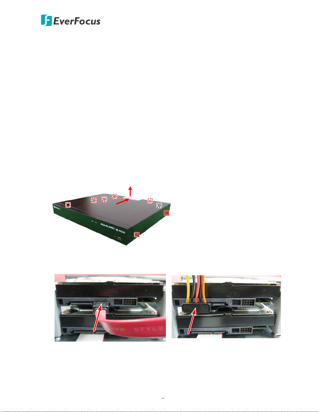
2.1 Hard Disk Installation
You can install two 3.5” HDDs inside the NVR for recording videos. The maximum capacity of
each HDD is 8TB.
1. Make sure the NVR is power-off.
2. Unscrew the eight housing screws (4 on the rear panel, 2 on the left and right side each). To
remove the housing cover from the NVR, push the cover backward and then lift it.
3. Find the SATA cable inside the NVR, and connect the SATA cable to the SATA port on the HDD
(left image). Find the internal power cable, and connect the internal power cable to the HDD
(right image).
IRONGUARD 16 POE
5
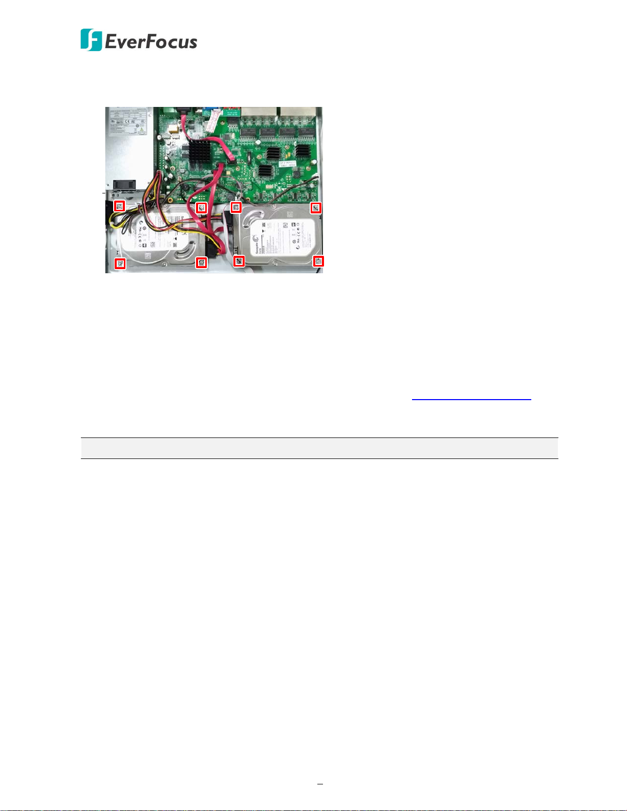
4. Place the HDDs inside the NVR, screw the HDDs from the bottom side of the NVR using the
supplied Screws.
5. Screw the housing cover back to the NVR.
2.1.1 Hard Disk Compatibility List
Please go to the product page (Download) on EverFocus’ Website www.everfocus.com.tw to see
the latest Storage Compatibility List. It’s recommended to use the hard disk models listed on the
Storage Compatibility List to ensure your hard disks are compatible.
Note: If using two or more hard disks, please choose the hard disks with the same capacity.
IRONGUARD 16 POE
6
Line Level
Audio Out
Line Level
Audio Input
IP Cameras
Main Monitor
(VGA)
Main Monitor
(HDMI)
Power Cord
Mouse / USB Storage
Web Remote Client
IP Cameras
Network
EverFocus CMS
1
3.5" HDD
2
3
3
4
5
6
7
8
Alarm Input:
16
Alarm Output
: 1
RS-485: 1
Alarm
IN
1615
14
OUT
COM
NO
RS485
-
+
G10987
654
3
2
1
13
12
11
G
GGG
G
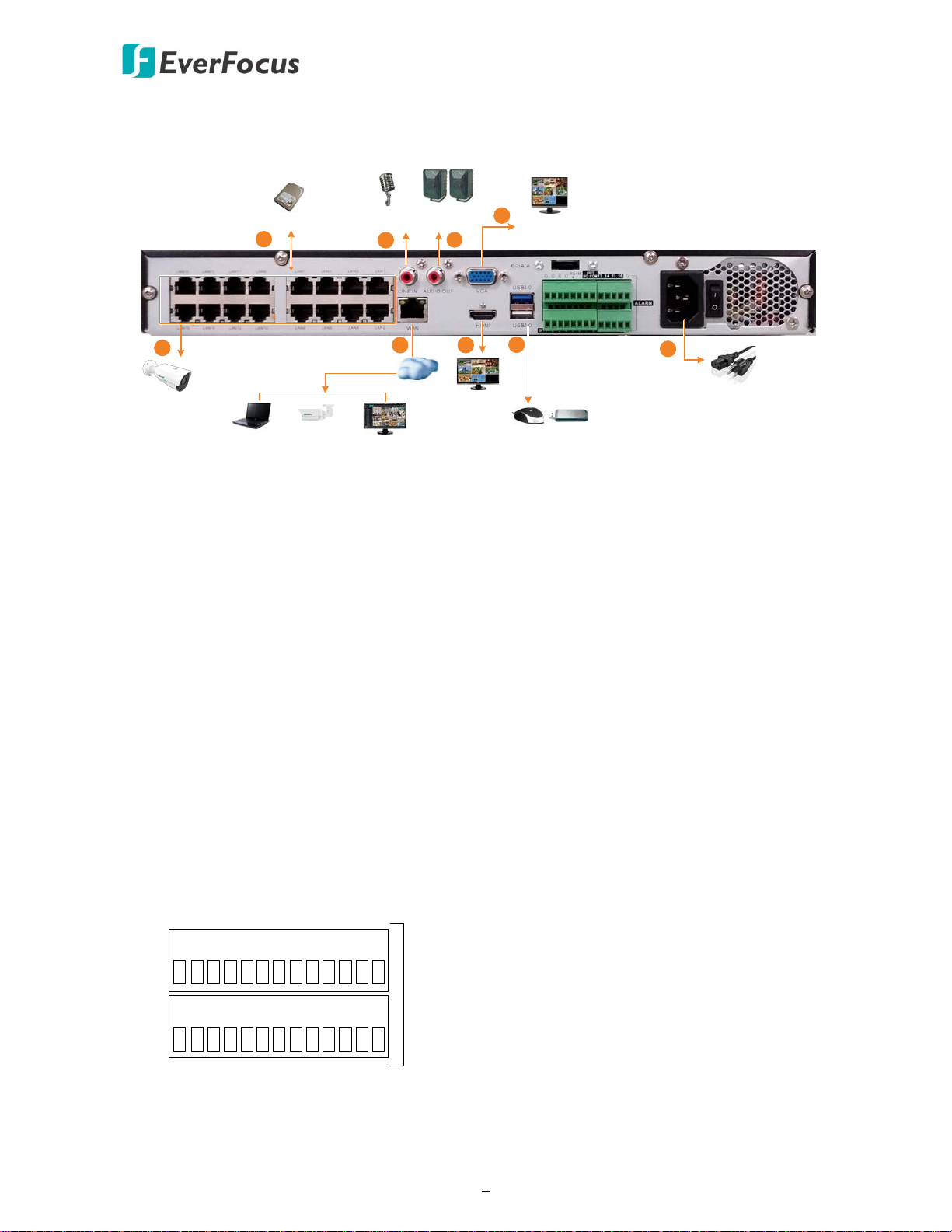
2.2 Basic Connection
The instructions below describe the basic connection to the NVR.
1. To record videos, install 3.5” HDD(s) to the NVR. Please refer to 2.1 Hard Disk Installation.
2. To connect to the IP cameras, connect the cameras to the LAN (PoE) ports.
3. To view videos at local site, connect a monitor to the HDMI or VGA port using the HDMI or
VGA cable supplied by the monitor manufacturer.
4. Connect microphones to the audio input ports to transmit audio from the NVR to the remote
sites (Web browser of NVR, eFVMS App or EverFocus CMS). Note that the microphones with
a (built-in) amplifier and external power supply are required.
5. To listen to the audio from IP cameras or remote sites, connect speakers to the audio output.
Note that the speakers with a (built-in) amplifier and external power supply are required.
6. Use a standard RJ-45 CAT5 Ethernet cable to connect the NVR to the network.
7. Optionally connect a mouse to the NVR to control the system. You can also control the
system using the supplied IR Remote Control (Appendix A. IR Remote Control).
8. Use the supplied Power Cord to connect the NVR to the power outlet.
2.2.1 Terminal Block
IRONGUARD 16 POE
7
IRONGUARD 16 POE
IRONGUARD 16
2.3 Accessing the Web Interface
You can look up the IP address and access the Web interface of the NVR using the IP Utility (IPU)
program, which is included in the software CD. The IP Utility can also be downloaded from
EverFocus’ Website: http://www.everfocus.com.tw/product/ip-utility/
Please connect the NVR on the same LAN of your computer.
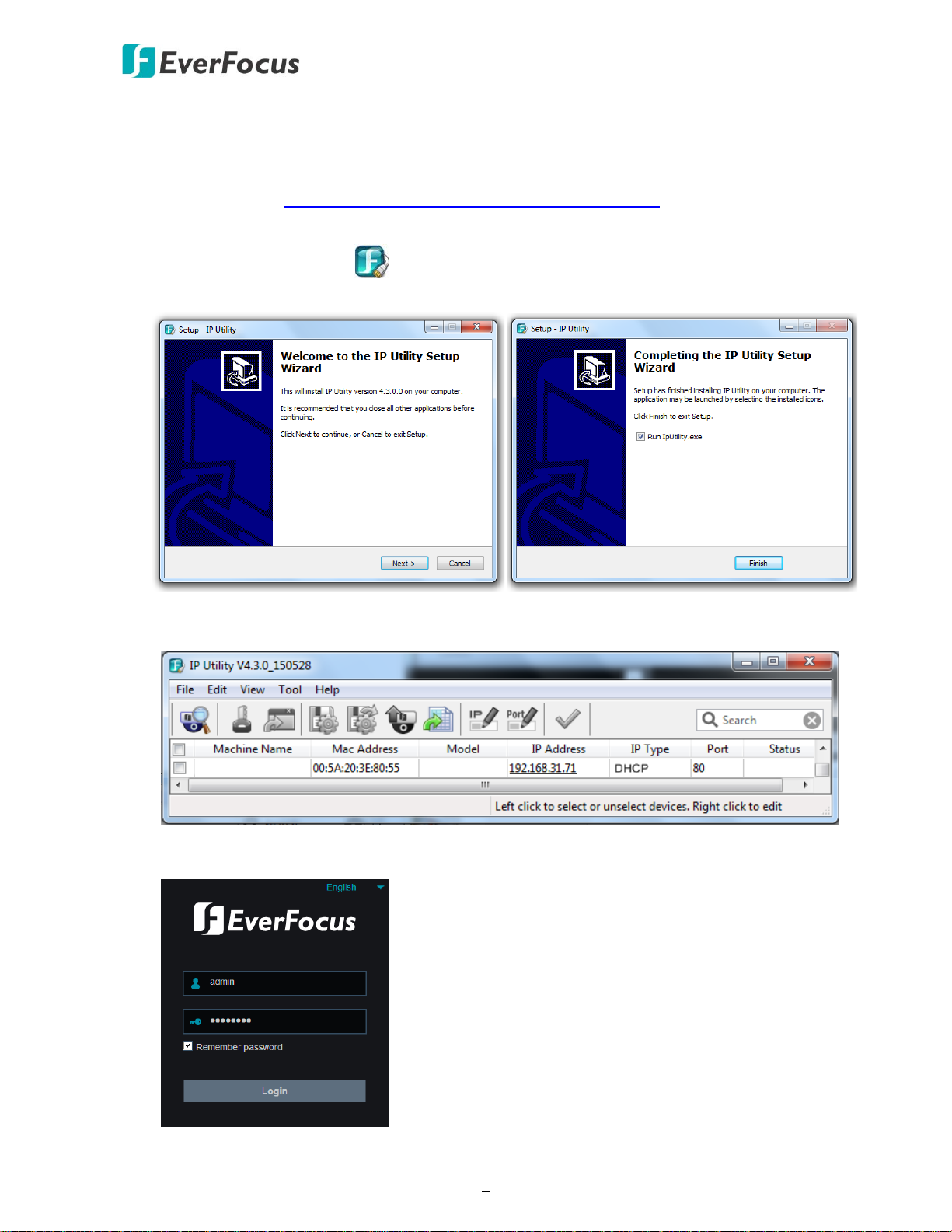
1. Save IP Utility Setup .exe in your computer. Double click the .exe file and follow the
on-screen instructions to install the IP Utility.
2. Click the Finish button, the IP Utility will be automatically launched to search the IP devices
connected on the same LAN.
3. To access the Live View window, double click the IP address of the desired device, the login
window pops up. Type the user ID and password to log in.
Note for the first time login:
IRONGUARD 16 POE
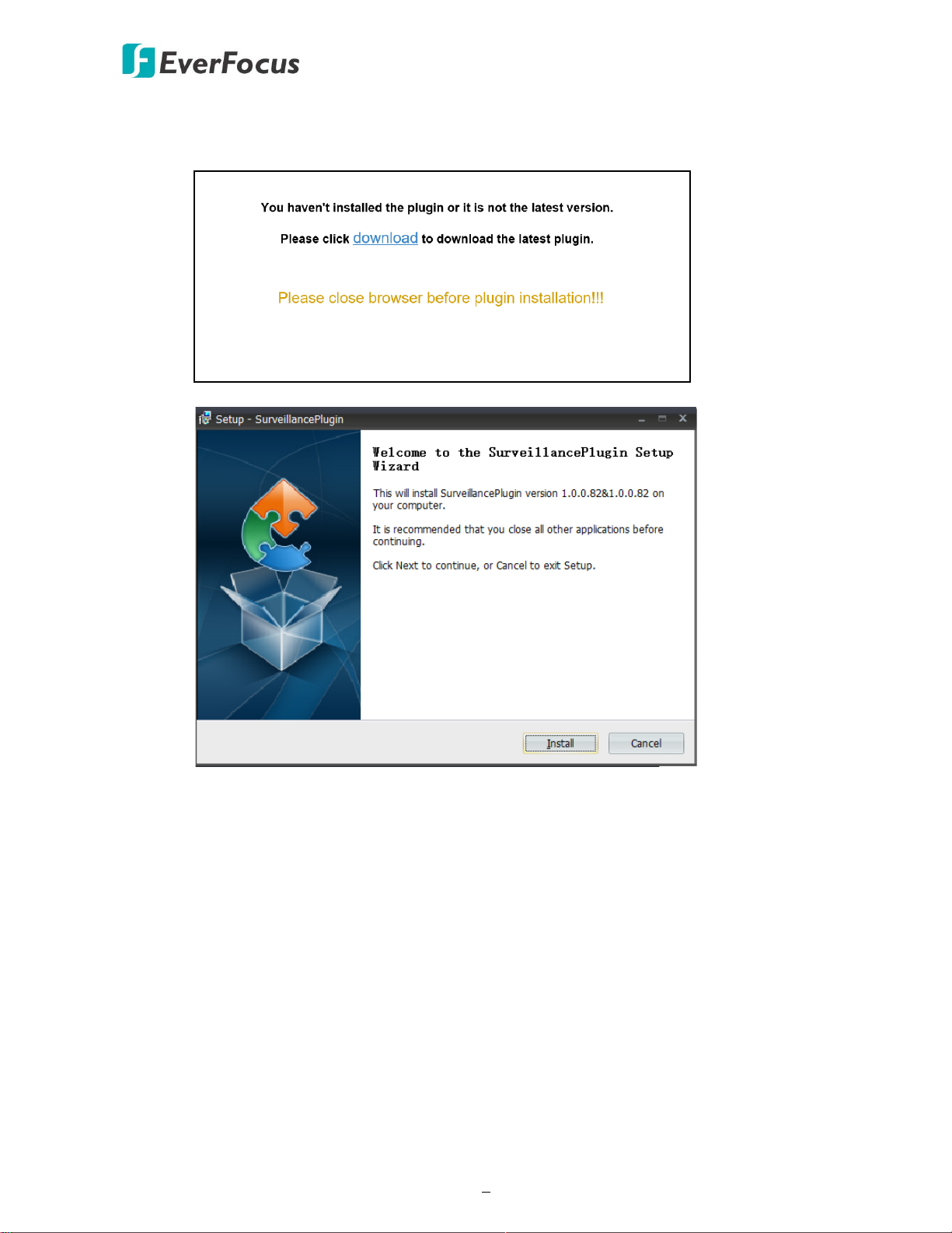
8
When the Plug-in blocked appears on the browser, click download to download the
plug-in and install to your computer. Reload the webpage and you should see the
remote live view page now.
If you encounter the following problem or still can’t access the remote Web interface, please
follow the instructions below:
If the ActiveX is not downloaded successfully, please check if your browser’s safety level or
firewall setting is set too high. Enable the following options on the Security Settings
window (IE Browser < Tools < Internet Options < Security < Internet < Custom Level).
Automatic prompting for ActiveX controls
Script ActiveX controls marked safe for scripting
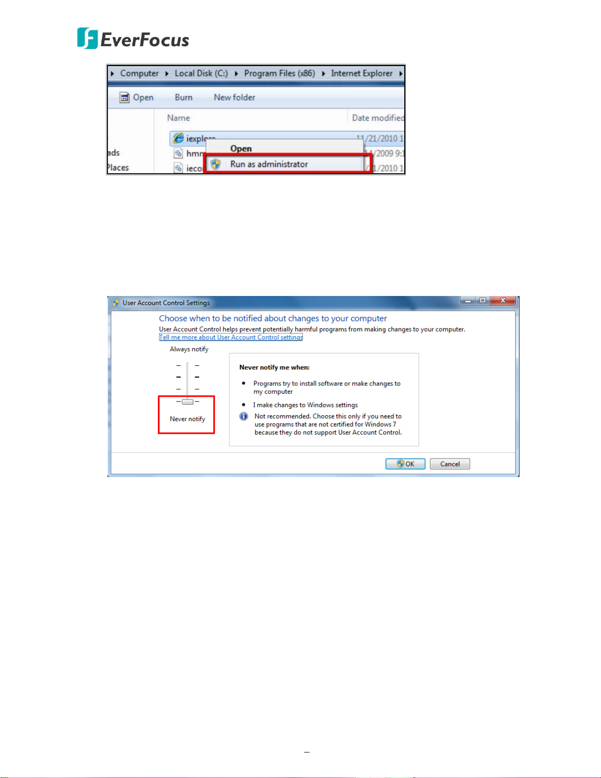
If your PC or laptop is running with Windows, it’s required to run the browser as
administrator when first entering the remote web page of the device. Go to C:\Program
Files (x86)\Internet Explorer, right-click the browser and then click Run as administrator.
IRONGUARD 16 POE
9
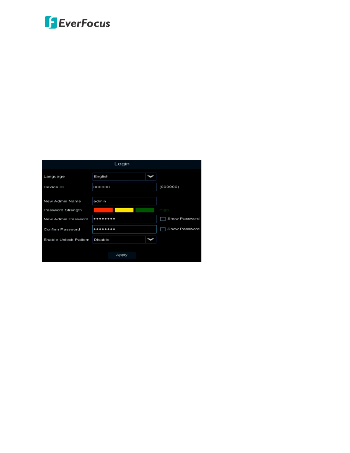
If you are unable to backup or record during remote operation, you may need to turn off
the firewall and turn User Account Control off.
To turn User Account Control off, on the computer, click Start > Control Panel > System
and Security > Action Center (click Change User Account Control Settings), the User
Account Control Settings window appears. Adjust the slide bar to Never Notify and then
click OK. Restart your computer if requested.
IRONGUARD 16 POE
10
3
Chapter
3. Getting Started
After pressing the power switch to turn on the NVR, the NVR will enter the System Initialization
process. When the process is done, it’s required to set up a password for the administrator
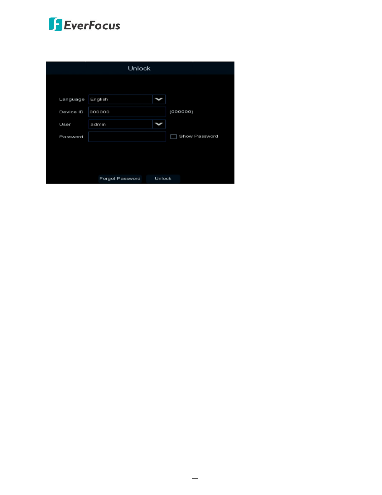
account immediately in order to protect your privacy.
Language: Select an OSD language.
Device ID: Input the device ID. The default ID is 000000. For more details about the Device ID,
please refer to 4.9.1.1 General.
New Admin name: Optionally input a name if you want to set up a name of the administrator
account.
Password Strength: Displays the security strength of the setup password.
New Admin Password: Set up a password of the administrator account. The password must be a
combination of at least 8 characters (alphabetic, numeric, or special characters).
Confirm Password: Enter the password again.
Enable Unlock Pattern: If you want to login the system with a pattern lock, select Enable from the
drop-down list and then click the Draw button to draw a pattern. To disable the Unlock Pattern
function, please refer to User Edit in 4.9.2 User Account.
Apply: Click to save the settings.
IRONGUARD 16 POE
11
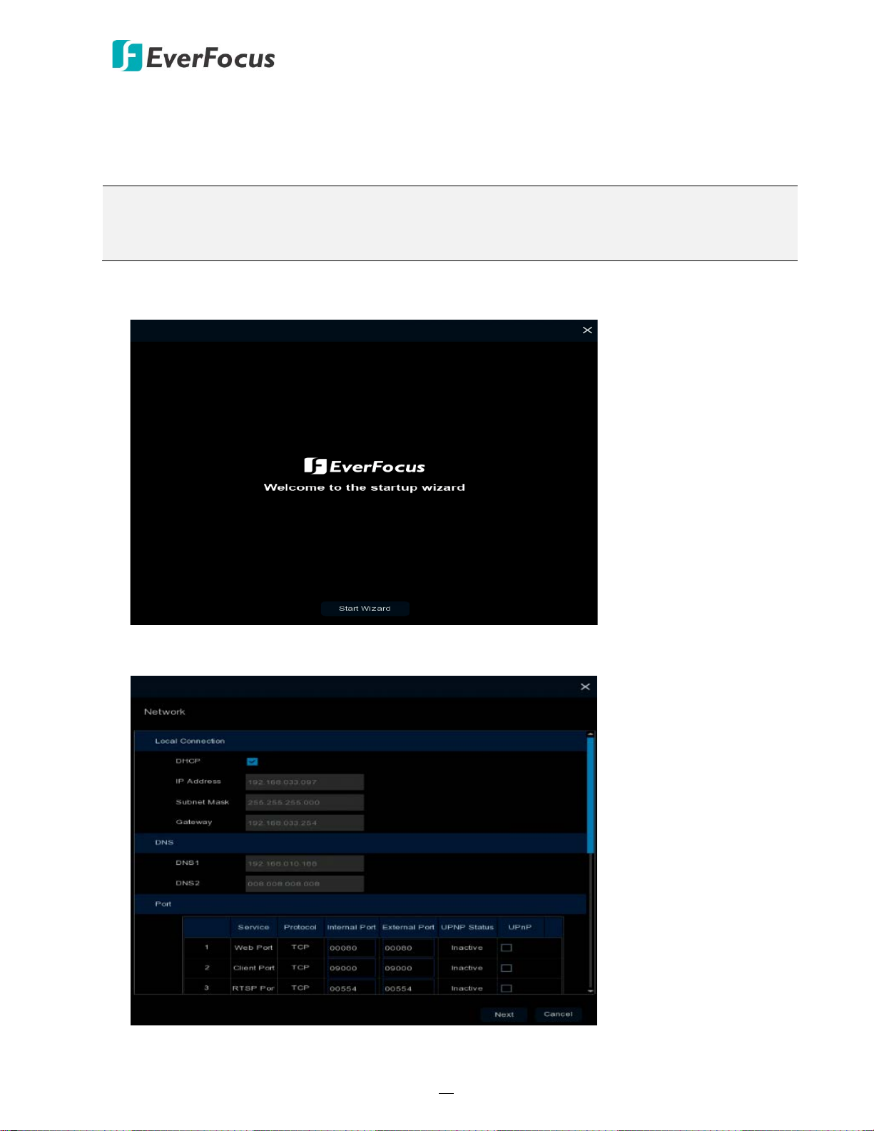
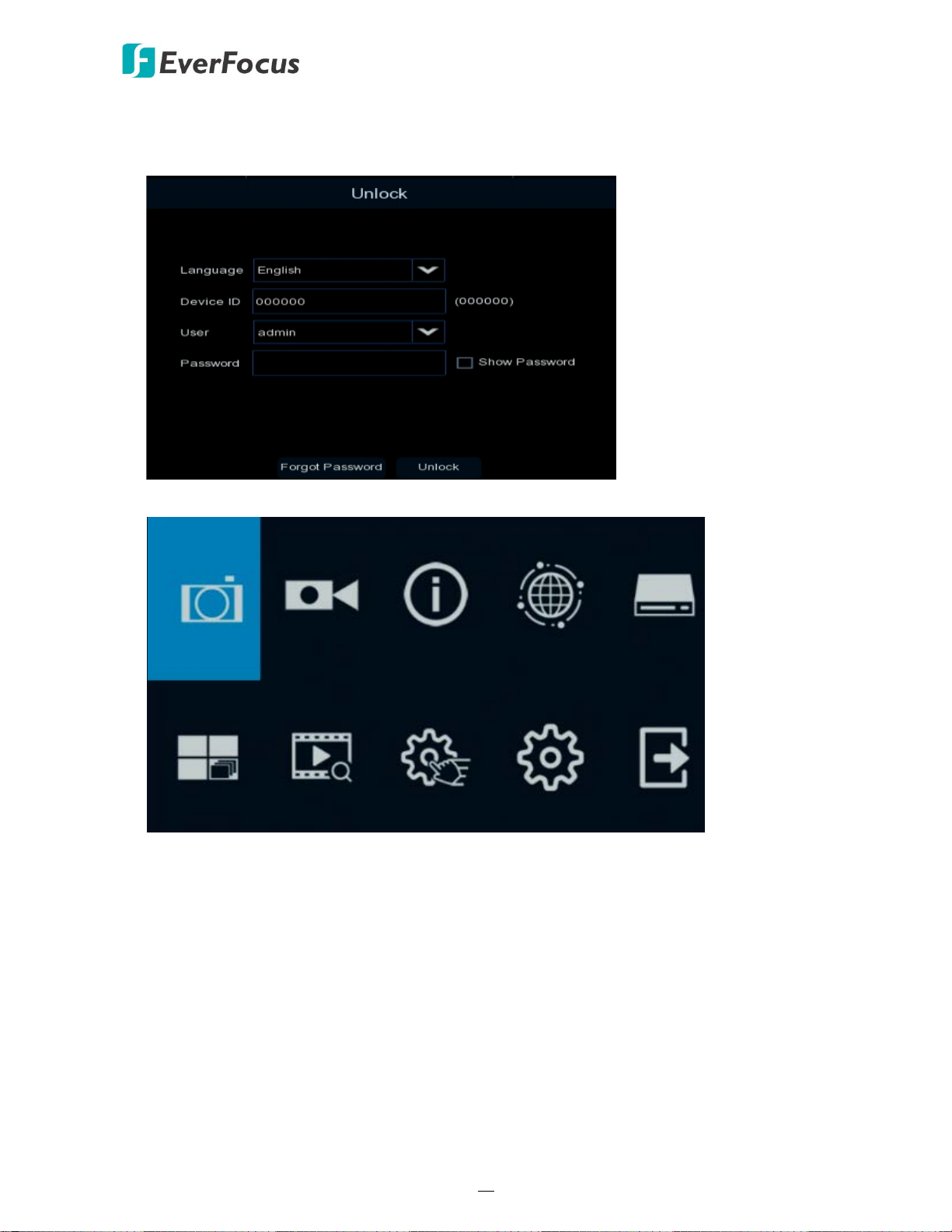
After clicking the Apply button, the below Unlock page appears. Input the User Name, Password
and then click Unlock.
3.1 Turning On / Off the Power
Before powering on the NVR, please make sure the internal HDDs have been installed properly.
Once you have completed the basic cable connections, you are ready to turn on the NVR. Simply
plug in the power source and then press the Power Switch on the rear panel of the NVR to turn
on the NVR. The POWER LED will light up if power is normal. Once the system has finished
loading, you can start setting up the menu options for the NVR.
To turn off the power, please refer to Shutdown in 4.10 Exit for more details.
IRONGUARD 16 POE
12
3.2 Startup Wizard
The Startup Wizard will guide you through some basic settings for the NVR. Please follow the onscreen instructions to proceed.
Note: If you don’t want to run the startup Wizard to make any settings when you restart the NVR
next time, you can go to OSD Menu > System > General and then uncheck the Start wizard
function.
1. Click the Start Wizard button to start with the startup wizard.
2. Configure the Network settings. Click Next to proceed.
【Local Connection】

IRONGUARD 16 POE
13
DHCP: For DHCP users, check DHCP, the router will automatically assign all the below IP
parameters to the NVR.
IP Address: The IP address of the NVR. The IP address consists of four groups of numbers,
separated by periods. For example, “192.168.001.100”.
Subnet Mask: Subnet mask is a network parameter which defines a range of IP addresses that
can be used on a network. The subnet address also consists of four groups of numbers,
separated by periods. For example, “255.255.000.000”.
Gateway: This address allows the NVR to access the Internet. The format of the Gateway
address is the same as the IP Address. For example, “192.168.001.001”.
【DNS】
DNS1 is the primary DNS server and DNS2 is a backup DNS server. Usually, it’s enough to just
enter the DNS1 server address.
【Port】
Web Port: The Web port can be used to remotely login the NVR (e.g. using the Web Client). If
the default port 80 is already taken by other applications, please change it.
Client Port: The Client port can be used to send information through (e.g. using the mobile
app). If the default port 9000 is already taken by other applications, please change it.
RTSP Port: The RTSP port allows the NVR to transmit real-time streaming to other devices (e.g.
using a streaming media player).
HTTPS: The Hypertext Transfer Protocol Secure (HTTPS) is a combination of the Hypertext
Transfer Protocol and the SSL/TLS protocol that provides encrypted communication and secure
identification of a network web server.
【PPPoE】
PPPoE is an advanced protocol that allows the NVR to connect to the network via a DSL
modem. To enable the PPPoE function, check Enable PPPoE, input the User Name and
Password provided by your Internet Service Provider.
IRONGUARD 16 POE
14
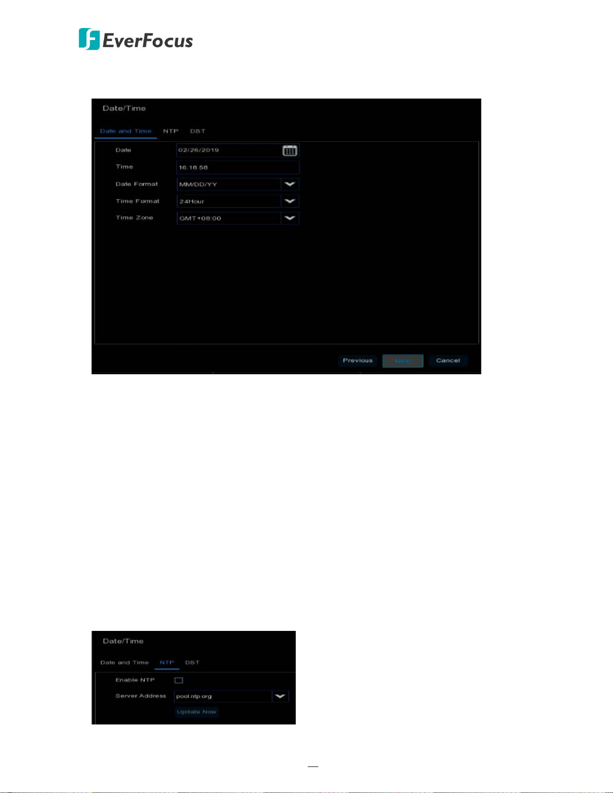
3. Configure the Date/Time settings. You can also configure the NTP and DST settings. Click Next
to proceed.
【Date and Time】
Date: Click on the calendar icon to set the system date.
Time: Click to set the system time.
Date Format: Select a date format from the drop-down list.
Time Format: Select a time format from the drop-down list.
Time Zone: Select a time zone of your region.
【NTP】
NTP stands for Network Time Protocol. This feature allows you to synchronize the NVR date
and time automatically over the Internet with the NTP server. Please ensure the NVR has been
connected to the Internet before enabling the NTP function.
To enable NTP, check Enable NTP, select an NTP server from the drop-down list or input one of
your region. Click Update Now.
IRONGUARD 16 POE
15
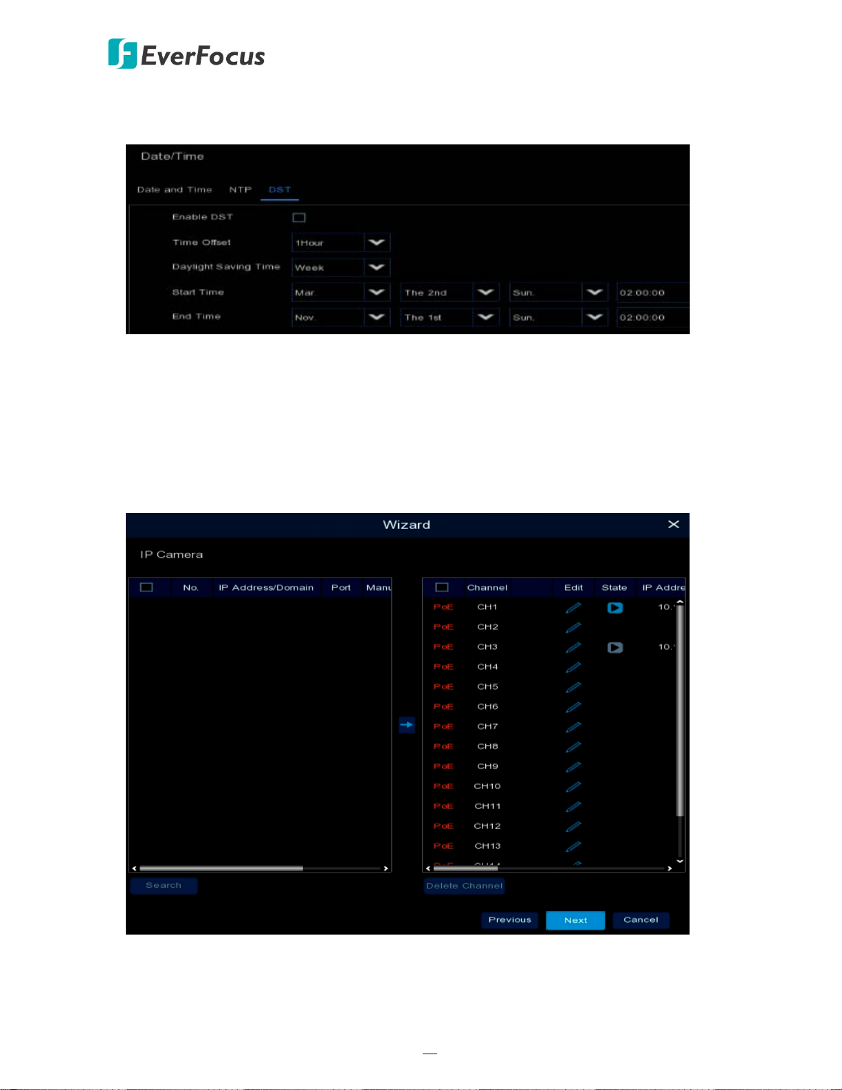
【DST】
DST stands for Daylight Saving Time.
Enable DST: Check the box to enable the Daylight Saving Time (DST) function.
Time Offset: Select the amount of time to offset for DST.
Daylight Saving Time: Choose to set up the daylight saving time in weeks or in days.
Start Time/End Time: Set the start time and end time for DST.
4. Add IP cameras to the NVR. By default, the system will automatically detect the IP cameras
connected to the PoE ports of the NVR. Please refer to 4.1.1.2 IP Channels for more details.
IRONGUARD 16 POE
16
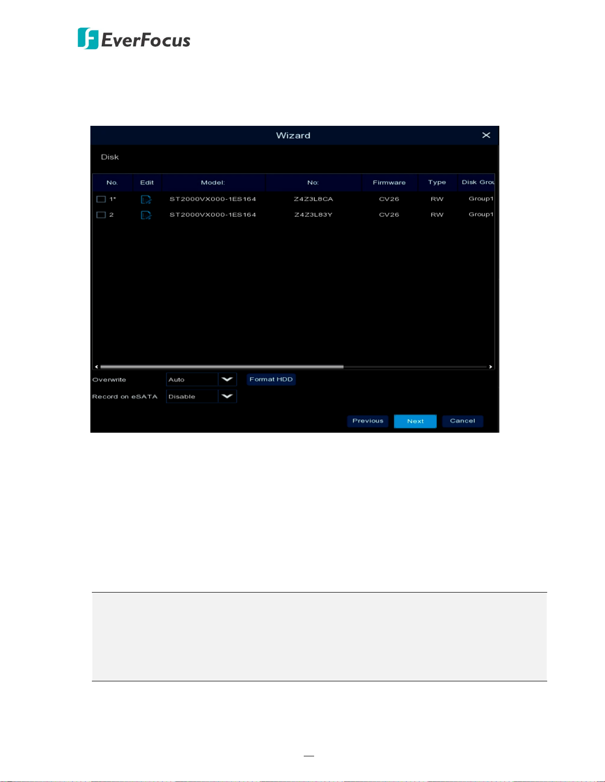
5. Configure the Disk settings. For the first time use HDD or a new HDD, users have to format the
HDD before use. Select the HDDs you want to format by checking the checkbox in the No
column and then click the Format HDD button. You can also setup to overwrite the HDD. Click
Next to proceed.
Overwrite: Select Auto to enable the overwrite function; Off to disable the overwrite function.
If Auto is selected, the NVR will overwrite the oldest files on the HDD when HDD is full. If Off is
selected, please check the HDD status regularly, to make sure the HDD is not full.
The 1/3/7/14/30/90 Days stands for the last number of days to keep in the HDD. For example,
if 3 Days is selected, the last 3 days recordings will be kept in the HDD.
Format HDD: The first time use HDDs have to be formatted before you can use it. Select the
desired HDDs and then click the Format HDD button to format the selected HDDs. Note that
only the HDDs with “Unformat” status displayed in the State column are required to format or
the recording function will not work. WARNING: This will effectively ERASE the ENTIRE hard
disk!! Please backup the data from HDDs before formatting the HDDs.
Note:
1. Only the HDDs with “OK” in the State column can perform the recording function. If not,
format the HDDs before start using the recording function.
2. The “Free Time” on the HDD list indicates the remaining time for the HDD to record
based on the pre-setup resolution, streaming and fps.
Record on eSATA: If you have connected an external eSATA storage device to the NVR, you
can enable the eSATA backup storage function.
IRONGUARD 16 POE
17
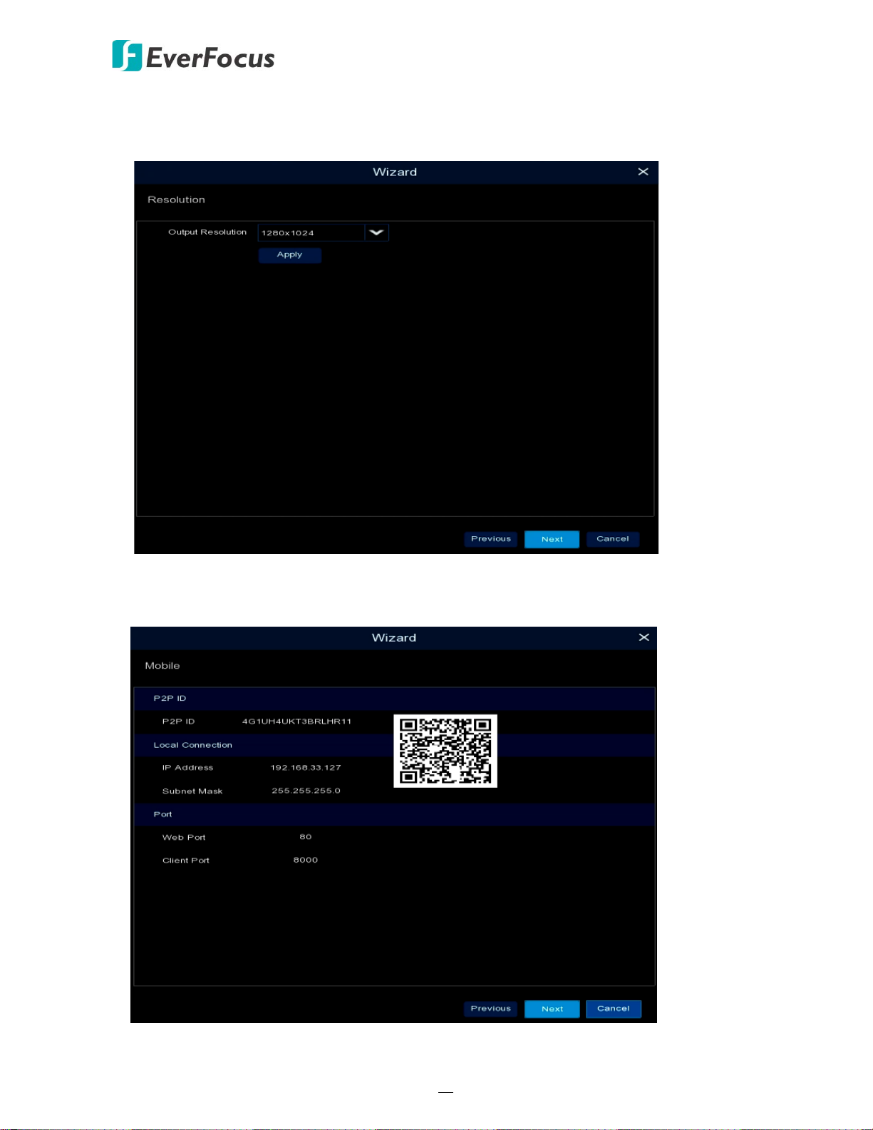
6. The NVR will apply the resolution best suit the connected monitor. If you want to change the
output resolution, select an output resolution that matches your monitor. Click the Apply
button. Click Next to proceed.
7. Mobile information. You can scan the QR code with EverFocus eFVMS App installed on your
mobile device to add the NVR to your app and then remotely access the NVR (please refer to
4.9.5.1 System Info for more details). Click Next to proceed.
IRONGUARD 16 POE
18
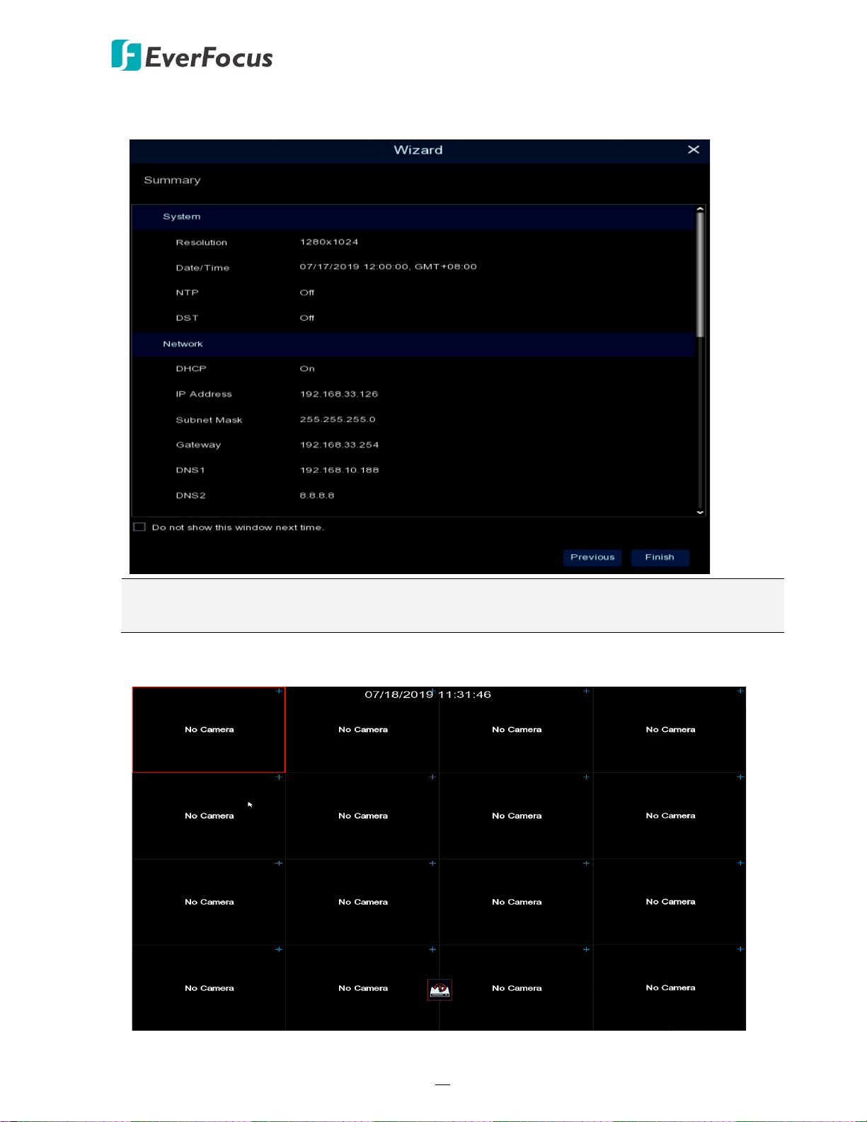
8. The setup information through this wizard will be displayed on the Summary page. Click Finish
to close the wizard.
Note: You can check “Do not show this window next time” if you do not want to run the
startup Wizard to make any settings when you restart the NVR next time.
9. After clicking the Finish button, the system will enter the Live View window (refer to 3.4 Live
View Window).
IRONGUARD 16 POE
19
Record Alarm Network Device
Layout Playback Express System Exit
Channel
10. To start using the NVR, click any function and the Unlock window appears. Input the password
of the NVR and then click the Unlock button to unlock the screen, the OSD Setup menu
appears. You can start using the NVR. Please refer to 4. OSD Menu for more details.
IRONGUARD 16 POE
20
Record Alarm Network Device
Layout Playback Express System Exit
Channel
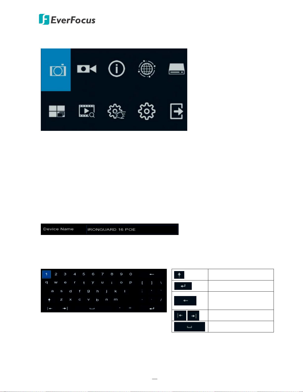
3.3 General Operation on the OSD Menu
【OSD Menu】
1. On the Live View window, right click the mouse, the OSD Menu appears.
2. Click on any icons to enter the setup menus.
3. To exit the OSD menu, right click the mouse. You can also exit each sub menu by right
clicking the mouse.
【Text Box】
Click on the box and an on-screen keyboard will appear.
【On-Screen Keyboard】
Click on a button to input that character.
Switch to capital letters
Confirm the selection
Delete the letter
backwards
Move to the left or right
Enter a space
IRONGUARD 16 POE
21
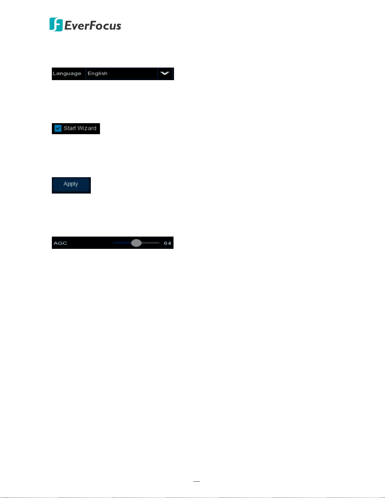
【Drop-Down Box】
Click on the down arrow to see all selections, then directly click on an option to select it.
【Check Box】
Click on the box to enable it (checked) or disable it (unchecked).
【Button】
Click the button to execute the function.
【Slider】
Slide the bar to the left or right for adjusting the value.
Loading...