


INSTRUCTION MANUAL
EDSR-400
4 Channel Duplex Digital Video Recorder
EDSR-600
6 Channel Duplex Digital Video Recorder
V1.05 2004/3/25
Safety Precautions
CAUTION
DO NOT REMOVE COVER. NO USER SERVICEABLE PARTS INSIDE.
REFER SERVICING TO QUALIFIED SERVICE PERSONNEL.
WARNING
TO REDUCE RISK OF FIRE OR ELECTRIC SHOCK,
DO NOT EXPOSE THIS APPLIANCE TO RAIN OR MOISTURE.
Safety Precautions
?Refer all work related to the installation of this product to qualified service personnel or system installers.
?Do not block the ventilation opening or slots on the cover.
?Do not drop metallic parts through slots.This could permanently damage the appliance. Turn the power off immediately and contact qualified service personnel for service.
?Do not attempt to disassemble the appliance.To prevent electric shock, do not remove screws or covers. There are no user-serviceable parts inside. Contact qualified service personnel for maintenance. Handle the appliance with care. Do not strike or shake, as this may damage the appliance.
?Do not expose the appliance to water or moisture, nor try to operate it in wet areas. Do take immediate action if the appliance becomes wet. Turn the power off and refer servicing to qualified service personnel. Moisture may damage the appliance and also cause electric shock.
?Do not use strong or abrasive detergents when cleaning the appliance body. Use a dry cloth to clean the appliance when it is dirty. When the dirt is hard to remove,use a mild detergent and wipe gently.
?Do not overload outlets and extension cords as this may result in a risk of fire or electric shock.
?Do not operate the appliance beyond its specified temperature, humidity or power source ratings. Do not use the appliance in an extreme environment where high temperature or high humidity exists. Use the appliance at temperature within 0o C ~ +40oC and a humidity below 90%. The input power source for this appliance is AC100~240V

Safety Precautions
Safety Precautions
The lightning flash with an arrowhead symbol, within an equilateral triangle, is intended to alert the user to the presence of uninsulated ”dangerous voltage”within the product’s enclosure that may be of sufficient magnitude to constitute a risk of electric shock to persons
The exclamation point within an equilateral triangle is intended to alert the user to presence of important operating and maintenance(servicing)instructions in the literature accompanying the appliance.
Warning :
To prevent fire or shock hazard, do not expose units not specifically designed for outdoor use to rain or moisture.
Attention:
Installation should be performed by qualified service personnel only in accordance with the National Electrical Code or applicable local codes.
Power Disconnect:
Units with or without ON-OFF switches have power supplied to the unit whenever the power code is inserted into the power source; however, the unit is operational only when the ON-OFF switch is in the ON position.
The power cord is the main power disconnect for all units.
AC100~240V Power Cords
Warning:
Electrostatic-sensitive device. Use proper CMOS/MOSFET handing precautions to avoid electrostatic discharge.
UNPACKING
Unpack carefully.
This is electronic equipment and should be handled carefully.
Check to ensure that the following items are included;
•1. Digital Video Recorder unit •2. User’s manual
•3. Power Cord
•4. HDD tray key and screws •5 Alarm I/O board
•6 C.F Card Reader (Optional)
If an item appears to have been damaged in shipment, replace it properly in its carton and notify the shipper.
Do not place on uneven or unstable work surfaces. Seek servicing if the casing.
Note:
This is a class A product. In a domestic environment this product may cause radio interference In which case the user may be required to take adequate measures.
Note:
Before installing and using this unit, please read this manual carefully. Be sure to keep it handy for later reference.
The information in this manual was current when published. The manufacturer reserves the right to revise and improve its products. All specifications are therefore subject to change without notice.

Important Safeguards
Important Safeguards
Read Instruction---All the safety and operating instructions should be read before the init is operated
Retain Instructions---The safety and operating instructions should be retained for future reference.
Heed Warnings— All warnings on the unit and in the operating instructions should be adhered to.
Follow Instructions— All operating and use instructions should be followed
Cleaning— Unplug the unit from the outlet before cleaning. Do not use liquid cleaners or aerosol cleaners. Use a damp cloth for cleaning
Attachments— Do not use attachment not recommended by the product manufacturer as they may cause hazards.
Water and Moisture— Do not use this unit near water-for example, near a bath tub, wash bowl, kitchen sink, or laundry tub, in a wet basement, near a swimming pool, in an
unprotected outdoor installation, or any area which is classified as a wet location.
Servicing— Do not attempt to service this unit yourself as opening or removing covers may expose
you to dangerous voltage or other hazards. Refer all servicing to qualified service personnel.
Power Cord Protection— Power supply cords should be routed so that they are not likely to be walked on or pinched by items placed upon or against them, playing particular attention to cords and plugs, convenience receptacles, and the point where they exit from the appliance.
Object and Liquid Entry— Never push objects of any kind into this unit through openings as they may touch dangerous voltage points or short-out parts that could result in a fire or electric shock, Never spill liquid of any kind on the unit.
|
Table of Contents |
|
|
|
|
1. |
Product Overview… … … … … … … … … … … … … … .… … … … … … ..… ..… ..Page 1 |
|
|
1.1 Main features… … … … … … … … … … … … … … … … … … … … … … … … … .....… ..… .1 |
|
|
1.2 Specifications… … … … … … … … … … … … … … … … … … … … … … … … ..… … … … ..2 |
|
2. |
Back panel connections… … … … … … … … … … … … … … … … … ......… … … 3~4 |
|
3. |
System connection… … … … … … … … … … .… … … … … … … … … … … … … … … ..5 |
|
|
Before installation… … ..… … … … … … … … … … … … … … … … … … … … … … … … … … ..5 |
|
4. |
Front panel keypads… … … … … … … … … … … … … … … … … … .… … … … ..… 6~7 |
|
5.Operation… … … … … … … … … … … … … … … … … … … … … … ..… … … … … … … … ..8
6. |
Menu flow… … … … … … … … … … … … … … … … … … … … … ..… … … … … … … ...9~10 |
|||
|
6.1 |
Clock setting menu… … … … … … … … … … … … … … … ...… … … … … … … … … … ..11 |
||
|
6.2 Timer setting menu… … … … … … … … … … … … … |
...… … … … … … … … … … … ..… 12 |
||
|
6.3 |
Sequence setting menu… … … … … … … … … … … |
..… … … … … … … … … … … … |
...13 |
|
6.4 |
Title setting menu… … … … … … … … … … … … … ..… … … … … … … … … … … … … ..14 |
||
|
6.5 |
Covert setting menu… … … … … … … … … … … … ..… … … … … … … … … … … … .… 15 |
||
|
6.6 |
Alarm record setting menu… … … … … … … … … ..… … … … … … … … … … … … … |
..16 |
|
|
6.7 |
Motion setting menu… … … … … … … … … … … … … … … … … … … … … … … … … |
...17 |
|
|
6.8 |
Record setting menu… … … … … … … … … … … … … … … … … … … … … … … … … ..19 |
||
|
6.9 Network setting menu… … … … … … … … … … … … … … … … … … … … … … … … .… 20 |
|||
|
6.10 Control setting menu… … … … … … … … … … … … … … … … … … … … … … .… … … 21 |
|||
|
6.11 Buzzer setting menu… … … … … … … … … … … … … … … … … … … … … … … … .… 22 |
|||
|
6.12 Archive setting menu… … … … … … … … … … … … … … … … … … … … … … … … … 23 |
|||
|
6.13 Call Monitor setting menu… … … … … ..… … … … … … … … … … … … … … … … … |
..24 |
||
|
6.14 Disk setting menu… … … … … … … … … … … … … … … … … … … … … … … … … … |
..25 |
||
|
6.15 System setting menu… … … … … … … … … … … … … … … … … … … … … … … … … 26 |
|||
7.Recording… … … … … … … … … … … … … … … … … … … … … … … … … … … … … ..… 27
|
7.1 |
Instant recording… … … … … … … … … … … … … … … … … … … … … … … … .… … … .27 |
||
|
7.2 Alarm recording… … … … … … … … … … … … … … … … … … … … … … … … … ...… … .27 |
|||
8. |
Playing back… … … … … … … … … … … … … … … … … … … … … … … .… … … |
...… … 28 |
||
|
8.1 |
Normal playback… … … … … … … … … … … … … |
… … … … … … … .… … … … … |
...… ..28 |
|
8.2 Search playback… … … … … … … … … … … … … |
… … … … … … .… … … ...… … ...29~31 |
||
9.Copy… … … … … … … … … … … … … … … … … … … … … … … … … .… … … … … .… … … .32
|
9.1 Still image copy… … … … … … … … … … … … … … … … … … … … |
.… … … … .… .… … .32 |
||||
|
9.2 Copy to movie file… … … … … … … … … … … … … … … … … … … .… … … … ...… … |
...33 |
||||
|
9.3 Export event log list.............................................................................................. |
|
|
|
|
34 |
10. |
Monitor Views / Operation.............................................................. |
|
|
|
35 |
|
|
10.1 Main monitor....................................................................................................... |
|
|
|
|
35 |
|
10.2 Call monitor… … … … |
.......................................................................................... |
|
|
|
36 |
11. |
Remote Control............. |
… … … … … … … … … … … … … … … ..… … … … .… … |
.37 |
|||
|
11.1 RS-485 remote control … … … … … … … … … … … … … … … … |
..… … … … .… … … .37 |
||||
|
11.2 IR – remote control |
… … … … … … … … … … … … … … … … … |
..… … … .… … … |
..… 38 |
||
12. |
View from Internet/Intranet… … … … … … … … … … … … … … … … … .… .... |
39~42 |
||||
|
Appendix-A LAN functional specification… … … ..… … … … … … … … … 43 |
|||||
|
Appendix-B Time lapse recording time table… … … ....… … .… ..… |
.44~45 |
||||
|
Appendix-C Serial Interface Specifications … … ..… … … … … … … … |
...46 |
||||
|
1. RS-232 Pin assignment.......................................................................................... |
|
|
|
46 |
|
|
2. Transmission settings............................................................................................. |
|
|
|
|
46 |
|
3. Remote control protocol................................................................................... |
|
|
47~50 |
||
|
Appendix-D Alarm I/O pin assignment....... |
… … … … … … … … … … … |
....51 |
|||

Product Overview
1. Product Overview
The EDSR400/EDSR600 Duplex Digital Video Recorder (DVR) a full-featured DVR designed specifically for use in security industry.
The DVR incorporates all the benefits of digital video recording, is simple to install, and operates just like a VCR.
Highly efficient compression technology and superior resolution of recorded images make the DVR stand out from the competition as the best choice for security surveillance.
The real time audio recording at any video recording speed that makes it as perfect as your security demand.
1.1 Main Features
A.Special Features:
?The real time audio recording at any video recording speed (1 pps or above) that makes it as perfect as your security demand.
?Adjustable Brightness, Contrast and Color for each channel.
?To export event log list/still image/movie file to CF card.
?Programmable motion detection area (16X12) for each channel.
B. General Features
?Easy-to-use control panel with common VCR and Multiplexer functions
?Shuttle/Jog dial for picture-by-picture or fast/slow viewing
?No tapes to manage, clean or replace
?Instant retrieval of stored video
?On-screen setup menu and system timer
?Ethernet TCP/IP connectivity for remote viewing and controlling
?Pre-Alarm recording
?Built-in M-JPEG compression/decompression with configurable video quality
?Programmed with various time-lapse speeds
?Two 3.5” IDE Type Hard Disks for storage with Hot-Swap trays
?RS232 and RS485 for Remote Control
??IR remote control (optional)
?Real-Time Live Display for all cameras
?Variable recording speeds up to 60/50 fields per second for NTSC/PAL
?Alarmand motion activated recording
?Data export to compact flash card
?2 channel real time audio recording capabilities
1
|
|
|
Specifications |
||||
|
|
|
|
|
|
|
|
1.2 Specifications |
|
|
|
|
|
||
|
|
|
|
|
|
|
|
|
|
Video Format |
NTSC/PAL |
|
|
|
|
|
|
|
|
|
|
|
|
|
|
Video Input |
4 (EDSR400) / 6 (EDSR600) camera inputs (BNC),1Vp-p/75ohm |
|
|
|
|
|
|
|
|
|
|
|
|
|
|
Video Output |
1 BNC video out (1Vp-p/75 ohm) for Main Monitor |
|
|
|
|
|
|
|
1 S-Video out Mini DIN for Main Monitor |
|
|
|
|
|
|
|
1 BNC video out (1Vp-p/75 ohm) for CALL Monitor output |
|
|
|
|
|
|
|
4 (EDSR400)/6 (EDSR600) video out (1Vp-p/ 75 Ohm)for looping |
|
|
|
|
|
|
|
|
|
|
|
|
|
|
Video Compression |
M-JPEG |
|
|
|
|
|
|
|
|
|
|
|
|
|
|
Recording Resolution |
720x484 (NTSC); 720x576 (PAL) |
|
|
|
|
|
|
|
|
|
|
|
|
|
|
Compact Flash Memory |
built-in Compact Flash card slot |
|
|
|
|
|
|
|
|
|
|
|
|
|
|
Alarm Input |
4 (EDSR400)/ 6 (EDSR600) alarm inputs, 25 pin Sub-D |
|
|
|
|
|
|
|
|
|
|
|
|
|
|
Alarm Output |
1 alarm output |
|
|
|
|
|
|
|
|
|
|
|
|
|
|
Video Display modes |
EDSR400: Full, 4, PIP and 2x zoom for Live and Playback |
|
|
|
|
|
|
|
EDSR600: Full, 4, 6, PIP and 2x zoom for Live and Playback |
|
|
|
|
|
|
|
|
|
|
|
|
|
|
Video Loss Detection |
Yes |
|
|
|
|
|
|
|
|
|
|
|
|
|
|
Ethernet |
10BaseT Ethernet, RJ45 connector |
|
|
|
|
|
|
|
|
|
|
|
|
|
|
Event Log |
Yes |
|
|
|
|
|
|
|
|
|
|
|
|
|
|
Hard Disk Storage |
Two 3.5” IDE type, hotswappable |
|
|
|
|
|
|
|
|
|
|
|
|
|
|
Recording Mode |
Continuous, Timer Schedule, Alarmor Motion Recording |
|
|
|
|
|
|
|
|
|
|
|
|
|
|
Recording Rate |
Up to 60/50 fields per second for NTSC/PAL |
|
|
|
|
|
|
|
|
|
|
|
|
|
|
Playback Rate |
Up to 60/50 fields per second for NTSC/PAL |
|
|
|
|
|
|
|
|
|
|
|
|
|
|
Playback Search |
By Date/Time, Event, Segment |
|
|
|
|
|
|
|
|
|
|
|
|
|
|
Setup |
On screen display setup (OSD) |
|
|
|
|
|
|
|
|
|
|
|
|
|
|
User Interface |
Menu Driven |
|
|
|
|
|
|
|
|
|
|
|
|
|
|
User Input Device |
Front Panel Keypad |
|
|
|
|
|
|
|
|
|
|
|
|
|
|
Timer |
Built-in real time clock |
|
|
|
|
|
|
|
|
|
|
|
|
|
|
Watch Dog Timer |
Yes |
|
|
|
|
|
|
|
|
|
|
|
|
|
|
RS-232 |
9-pin female D-Sub |
|
|
|
|
|
|
|
|
|
|
|
|
|
|
RS485 |
2 x RJ45 Socket |
|
|
|
|
|
|
|
|
|
|
|
|
|
|
Audio |
2 x Audio In / Out Cinch 500mV max., 10 KOhm impedance |
|
|
|
|
|
|
Dimension |
430mm (W) x 88mm (H) x 300 (D) |
|
|
|
|
|
|
Power Consumption |
100W max. |
|
|
|
|
|
|
|
|
|
|
|
|
|
|
Power Source |
AC100~240V |
|
|
|
|
|
|
|
|
|
|
|
|
|
|
Operating Temperature |
0°C ~ 40°C; 20~80% |
|
|
|
|
|
|
|
|
|
|
|
|
2

Back Panel Connections
2. Back Panel Connections
5 |
EDSR-600 |
3 |
2 1 |
|
4 |
|
6 |
7 |
8 |
9 |
10 |
11 |
12 |
13 |
|
|||||||
5 |
EDSR-400 |
4 |
3 |
|
|
2 1 |
|
|
|
|
|
|
|
||
1
2
3
4
5
6
7
6 |
7 |
8 |
9 |
10 |
11 |
12 |
13 |
|
ON/OFF: |
Main on/off switch. |
AC100~240V |
power socket. |
VIDEO IN: |
BNC-sockets for composite signal video inputs, automatic 75 Ohm |
|
termination. (EDSR400:1~4, EDSR600: 1~6) |
VIDEO OUT: |
Loop through video outputs for each input channel. |
|
(EDSR400:1~4, EDSR600: 1~6) |
CALL MONITOR: BNC-socket Call (Spot) Monitor, composite signal. (Full screen display only)
MAIN MONITOR: BNC-socket main monitor, composite signal. Main monitor provides Full screen, Multi-screen, Setup.
S-VIDEO: Mini-DIN socket main monitor, S-Video signal. Main monitor provides Full screen, Multi-screen, Setup.
8AUDIO IN : 2 x Cinch socket audio input 500 mV max., 10 KOhm impedance.
AUDIO OUT: 2 x Cinch socket audio output 500 mV max. at 10 KOhm
3

Back Panel Connections
9ALARM I/O: (Refer pin assignment in Appendix-D, Page 44)
ALM-INPUT : Normally Open (N.O) or Normally Close (N.C) type alarm sensor input. The Alarm Input can be selected as N.O or N.C input in the setup menu. When an alarm occurs, alarm recording will automatically start.
ALM-OUTPUT : Two-way contact relay alarm output. In normal condition, this N.C. contact
|
shorted to |
ALM-COM. In alarm status, it is open between ALM-NC and |
|
ALM-COM, N.O. is shorted to ALM-COM. |
|
10 RS232 connector : D-Sub 9 pins connector to RS232 ports for remote control. |
||
11 |
RS485 connector : 2 x RJ-45 connectors for RS-485 remote control, high impedance |
|
|
Supported are keyboards KS-KBK, KS-KBJ (Optional). |
|
|
Maximum units in RS-485 network are 32. |
|
|
Following EverFocus products are compatible in RS-485 network: |
|
|
- DVR’s |
EDSR100H, EDSR100M, EDSR400H, EDSR400M, |
|
|
EDSR400, EDSR600, EDSR900, EDSR1600 |
|
- Keyboards KS-KBJ (with 3 - axis Joystick, DVR and telemetry control) |
|
|
|
KS-KBK (only DVR control) |
12 |
LAN Connector : RJ-45 LAN connector for internal 10MBit LAN interface. |
|
13 |
FAN: Cooling fan, do not cover. |
|
4
System Connection
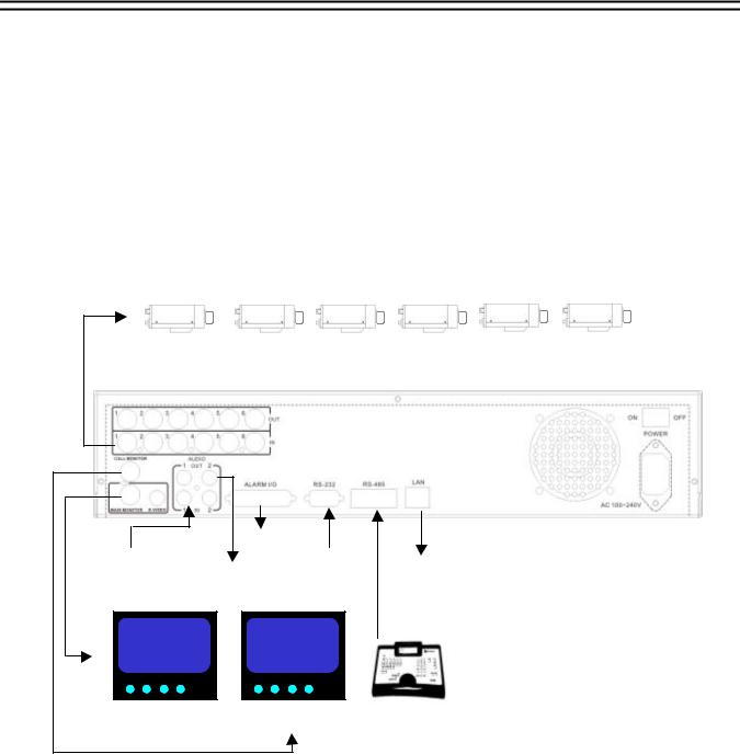
3. System Connection
The installations described below should be made by qualified service personnel or system installers.
Before Installation
Please refer to the following diagram for the system connections.
EDSR 400: Camera 1~4 / EDSR-600: Camera 1 ~ 6
|
|
Alarm In/Out |
|
|
Audio Input |
|
RS232 |
Ethernet |
|
(camera Audio Out) |
|
|||
Audio Out |
||||
|
(To Speaker) |
|
||
|
|
|
RS-485 |
|
MAIN Monitor |
CALL Monitor |
Remote Keyboard(s) |
||
KS-KBJ / KS-KBK |
||||
|
|
|
||
|
|
|
(optional) |
|
5
Front Panel Keypads
4. Front Panel Keypads
12 |
11 |
10 |
|
|
|
EDSR-600 |
2 |
1 |
||
|
|
|
|
|
|
|
|
|||
|
|
|
|
|
22 |
|
|
|
|
|
|
|
9 |
8 |
7 |
6 |
5 |
4 |
3 |
|
|
13 |
14 |
15 |
16 |
17 |
18 |
19 |
20 |
21 |
|
2
1
2
EDSR-400
SHUTTLE Ring and JOG Dial
SHUTTLE : In Playback mode, turn the shuttle ring to fast forward/rewind the picture (600X maximum).
In Pause mode, turn the shuttle dial to slow forward/rewind the picture (1/32 maximum).
JOG : In Pause mode, turn the jog dial to step forward/rewind the Picture.
In Menu mode turn the jog dial to select options.
CHANEL KEYS:.
Press these keys 1 ~ 6 (EDSR400: 1~4) to display video image in full screen
format, the picture of the corresponding camera will fill the whole screen of the monitor display.
3MENU: Press this key to enter Setup Menu (Please refer to page 9~25 for details).
4CALL: Press this key to show picture of assigned camera to desired call monitor.
5SEQ : Press this key to enter the auto sequential switching mode for main monitor.
6ZOOM: Press this key while viewing the full screen image to display X2 zoom-in picture. To move the zooming area, use JOG to move from left to right. Press ENTER for changing vertical / horizontal movement.
7MODE: Switch Full, 4, (6 for EDSR600), PIP (picture in picture) multi-screen for Live and Playback.
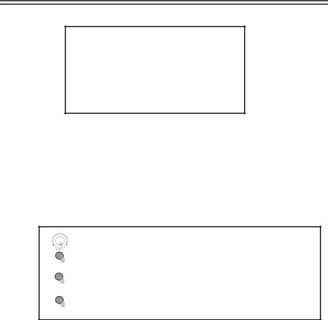
8 |
SELECT: In Full screen mode: press this key to pop-up dialog as below: |
DISPLAY SETTING MENU
CHANNEL 01
BRIGHTNESS
CONTRAST
COLOR
HIT SELECT TO DISCARD CHANGE
HIT MENU TO SAVE AND EXIT
6

Front Panel Keypads
In Full screen mode this menu allows color adjustment for each video channel, all channels are separately adjustable.
The selected item will show in red color bar. Use JOG to increase or decrease the value. Press ENTER to confirm and move to next item. After finished setting, press SELECT key to discard change or press MENU key to save and exit the dialog.
In Multi-screen mode:
In Multi-screen mode the SELECT key allows to define cameras in all multi-screen views.
Press SELECT. At the upper left camera in multi-screen appears “SELECT”.
Use the numeric camera keys (1~6) to select a camera.
Press ENTER to switch in the multi-screen.
Press SELECT to exit this setting.
Note: Every camera can be selected only once for a multi-screen view.
Note: If the password is “ENABLE”, hold “SELECT” button for approximately 2 seconds to logout the system (Return to Level 1).
9 Display: Press this key to switch ON/OFF for camera title, date/time and HDD status.
Hold this key longer than 2 seconds for displaying the event log list.
10Compact Flash Card Slot: Insert a Compact Flash Card for archiving video.
11Hard Disk Trays: 2 x Hard Disk holder for 3.5” HDD.
12HDD locks: Turn on HDD power and protection from taking out the HDD without authority.
13REC: Press this key to start recording.
14STOP: Press this key to stop recording or playing back.
15PLAY: Press this key to stat playing back recoded picture (Please refer to page 27 for details).
16PAUSE: Press this key to pause the playback picture.
17SEARCH: Press this key to enter the Search Menu (Please refer page 28~30 for details).
18COPY: Under PAUSE or PLAYBACK, Press this key to start copying still picture or video stream into Compact Flash card (Please refer page 31~33 for details).
19ENTER: Press this key to enter sub-menu or confirm setup. When there is Alarm, Motion or Video Loss occurs, press this key for alarm reset. The Event Log Dialog will show on the display, then follow the instruction to continue.
20LEDs: LEDs for HDD1, HDD2 , ALARM and LAN access (from left to right).
21IR Remote Controller receiver
22LCD Panel: To display Date/Time, Recording/Playback and HDD status.
7

Operation
5. Operation
(1) Insert a HDD (IDE) for Video Storage
Insert one or two HDD (3.5” IDE) for Video Storage.
The HDD should be set as Master. (Set Cable Select is also available) (Normally the default setting of HDD is Master)
Note: After hard disk case is inserted into the hard disk tray, be sure to turn the tray key in lock position.Otherwise, HDD will not be detected.
ATTENTION: Changing HDD’s and switching on HDD’s is not allowed during recording!
(2)Connect cable for video/audio input and video/audio out,
The detail connection is described in SYSTEM CONNECTION.
(3)Switch Power On
The LCD panel in the front panel will light when you switch on the power.
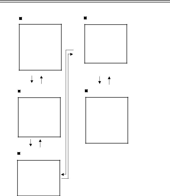
(4)Press MENU key to enter SET UP MENU.
Once inside the main menu you will find there are 14 set up pages as below:
Selected item will be surrounded by a white block.
MENU
MAIN MENU
CLOCK
TIMER
SEQUENCE
TITLE
COVERT
ALARM
MOTION
RECORD
NETWORK
CONTROL
BUZZER
ARCHIVE
CALL
DISK
SYSTEM
(5) |
Turn the JOG dial clockwise or counter-clockwise to select the item, |
|
press ENTER key for detail set up for each item. |
(6) Press MENU again to leave the set up menu.
8

MENU flow
6. MENU FLOW
CLOCK
( See page 11 )
CLOCK SETTING MENU
DATE |
: |
2004/2/27 FRI |
TIME |
: |
13:01:02 |
MENU LANGUAGE: ENGLISH
VIDEO SYSTEM: NTSC
VERSION: 1.05
TIMER
( See page 12 )
TIMER SETTING MENU
WEEK START STOP SPEED SET
SUN |
00:00 |
23:59 |
60 IPS |
OFF |
|
SUN |
00:00 |
23:59 |
60 IPS |
OFF |
|
SUN |
00:00 |
23:59 |
60 IPS |
OFF |
|
SUN |
00:00 |
23:59 |
60 IPS |
OFF |
|
SUN |
00:00 |
23:59 |
60 IPS |
OFF |
|
SUN |
00:00 |
23:59 |
60 IPS |
OFF |
|
SUN |
00:00 |
23:59 |
60 IPS |
OFF |
|
SUN |
00:00 |
23:59 |
60 IPS |
OFF |
|
SUN |
00:00 |
23:59 |
60 IPS |
OFF |
|
|
|||||
SUN |
00:00 |
23:59 |
60 IPS |
OFF |
|
SUN |
00:00 |
23:59 |
60 IPS |
OFF |
|
SUN |
00:00 |
23:59 |
60 IPS |
OFF |
|
SUN |
00:00 |
23:59 |
60 IPS |
OFF |
|
SUN |
00:00 |
23:59 |
60 IPS |
OFF |
|
SUN |
00:00 |
23:59 |
60 IPS |
OFF |
|
SUN |
00:00 |
23:59 |
60 IPS |
OFF |
|
SEQUENCE
( See page 13 )
SEQUENCE SETTING MENU
CH OP DWELL
1ON 03 SECS
2ON 03 SECS
3ON 03 SECS
4ON 03 SECS (5 ON 03 SECS) (6 ON 03 SECS)
TITLE
( See page 14 )
TITLE SETTING MENU
CH TITLE
1CH01:_ _ _ _ _
2CH02:_ _ _ _ _
3CH03:_ _ _ _ _
4CH04:_ _ _ _ _
( 5 CH05:_ _ _ _ _ ) ( 6 CH06:_ _ _ _ _ )
COVERT
( See page 15 )
COVER SETTING MENU
CH OP
1OFF
2OFF
3OFF
4OFF
(5 OFF) (6 OFF)
ALARM
( See page 16 )
ALARM SETTING MENU
CH OP TYPE DURATION
1 |
ON N.O |
05 SECS |
2 |
ON N.O |
05 SECS |
3 |
ON N.O |
05 SECS |
4 |
ON N.O |
05 SECS |
(5 |
ON N.O |
05 SECS) |
(6. |
ON N.O |
05 SECS) |
RST ON N.O
MOTION
( See page 17 )
CH |
OP SEN |
DURATION |
1 |
ON HIGH |
07 SECS |
2 |
ON HIGH |
07 SECS |
3 |
ON HIGH |
07 SECS |
4 |
ON HIGH |
07 SECS |
(5 |
ON HIGH |
07 SECS ) |
(6 |
ON HIGH |
07 SECS) |
RECORD
( See page 19 )
RECORD SETTING MENU
NORMAL RECORD
SPEED |
: 60 IPS |
|
QUALITY |
: STANDARD |
|
DISK FULL |
||
: REWRITE |
||
ALARM RECORD |
|
|
OPERATION |
ON |
|
SPEED |
: 60 IPS |
|
QUALITY |
||
: STANDARD |
||
PRE-ALARM RECORD |
||
OPERATION |
ON |
|
NETWORK
( See page 20)
NETWORK SETTING MENU
IP ADDRESS |
:192.168.010.005 |
NET MASK |
:255.255.255.000 |
GATEWAY |
:192.168.010.001 |
USER-MANE PASSWORD LEVEL
GUEST |
GUEST |
GUEST |
GENERAL |
GENERAL |
GENERAL |
SUPER |
SUPER |
SUPER |
CONTROL
( See page 21)
CONTROL SETTING MENU
RS232 BAUD RATE |
: 9600 BPS |
RS232 STOP BIT |
: 1 |
RS232 PARITY |
: NONE |
RS232 DATA BIT |
: 8 |
RS485 BAUD RATE |
: 9600 BPS |
RS485 STOP BIT |
: 1 |
RS485 PARITY |
: NONE |
RS485 DATA BIT |
: 8 |
RS232/RS485 ID |
: 1 |
9
MENU flow
BUZZER
( See page 22 )
BUZZER SETTING MENU
BUZZER : ENABLE
RECORD-IN : ON
ALARM-IN : ON
MOTION-IN : ON
DISK FULL : ON
VIDEO LOSS: ON
TIMER : ON
ARCHIVE
( See page 23 )
ARCHIVE SETTING MENU
PICTURE SIZE |
: 720 X 480 |
TIME STAMP |
: ON |
TIME STAMP POS |
: TOP |
WATER MARK |
: ON |
WATER MARK POS |
: TOP |
CALL
( See page 24 )
CALL MONITOR SETTING MENU
CH DWELL EVENT
1 |
07 SECS |
NONE |
2 |
07 SECS |
NONE |
3 |
07 SECS |
NONE |
4 |
07 SECS |
NONE |
5 |
07 SECS |
NONE |
6 |
07 SECS |
NONE |
DISK
( See page 25 )
SYSTEM SETTING MENU
DISK USAGE |
HDD-1 |
HDD-2 |
SIZE (GB) |
: 160 |
160 |
RECORD POS |
: *67.8% |
0% |
PLAY POS |
: *34.5% |
0% |
DISK RENEW |
: NO |
NO |
SYSTEM
( See page 26 )
SYSTEM SETTING MENU
PLAY WITH AUDIO- 1: ON PLAY WITH AUDIO- 2: ON MULTI-EVENT DWELL: 02 SECS
PASSWORD ENABLE: DISABLE PASSWORD LEVEL-2: 222222 PASSWORD LEVEL-3: 333333 MULTI-EVENT DWELL: 02 SEC
SYSTEM UPDATE: NO
LOAD DEFAULT: NO
10

MENU
6.1 CLOCK SETTING MENU
|
CLOCK SETTING MENU |
|
DATE |
: 2004/02/27 FRI |
|
TIME |
: 13:01:02 |
: ENGLISH |
MENU LANGUAGE |
||
VIDEO SYSTEM |
: NTSC |
|
VERSION: 1.05 2004/03/25
In CLOCK/LANGUAGE SETTING MENU , we define:
(1) DATE : Current date, format: YYYY/MM/DD
Year: 2000 ~ 2099, Month: 01~ 12, Date: 01~31, Week: Sunday~Saturday
(2) TIME : Current time, format: HH:MM:SS
Hour: 00 ~ 23, Minute : 00 ~ 59, Second: 00 ~ 59
(3)MENU LANGUAGE: ENGLISH or Others
(4)VIDEO SYSTEM: Factory default setting depend on machine “NTSC” or “PAL” .
(5)VERSION: Current S/W revision and release date.
Turn the JOG dial clockwise or counter-clockwise to select the options.
Press ENTER key to confirm the option and move to next column.
ENTER
Press CALL key to confirm the option and move to previous column.
CALL
Press MENU key to return to Main Menu, press again to leave Set up Menu.
MENU
11

MENU
6.2 TIMER SETTING MENU
TIMER SETTING MENU |
|
|||
WEEK |
START |
STOP |
SPEED SET |
|
SUN |
00:00 |
23:59 |
50 IPS |
OFF |
SUN |
00:00 |
23:59 |
50 IPS |
OFF |
SUN |
00:00 |
23:59 |
50 IPS |
OFF |
SUN |
00:00 |
23:59 |
50 IPS |
OFF |
SUN |
00:00 |
23:59 |
50 IPS |
OFF |
SUN |
00:00 |
23:59 |
50 IPS |
OFF |
SUN |
00:00 |
23:59 |
50 IPS |
OFF |
SUN |
00:00 |
23:59 |
50 IPS |
OFF |
SUN |
00:00 |
23:59 |
50 IPS |
OFF |
SUN |
00:00 |
23:59 |
50 IPS |
OFF |
SUN |
00:00 |
23:59 |
50 IPS |
OFF |
SUN |
00:00 |
23:59 |
50 IPS |
OFF |
SUN |
00:00 |
23:59 |
50 IPS |
OFF |
SUN |
00:00 |
23:59 |
50 IPS |
OFF |
SUN |
00:00 |
23:59 |
50 IPS |
OFF |
SUN |
00:00 |
23:59 |
50 IPS |
OFF |
|
|
|
|
|
In TIMER SETTING MENU we define automatic timer controlled records.
Timer records can be defined for 12 individual start and end times.
(1) WEEK: This select the week day for the timer to record on schedule. DLY means daily record.
(2)START: Enter the start time for timer recording.
(3)STOP: Enter the end time for timer recording.
NOTE: The recorder records till the end of the minute, which is set here. EXAMPLE: START 07:00 END 08:00
The recorder records from 07:00:00 till 08:00:59
Each day has to be set separately:
EXAMPLE: Daily record from 20:00 till next day 07:00
WRONG: DLY |
START 20:00 |
STOP 07:00 |
|
CORRECT: DLY |
START |
20:00 |
STOP 23:59 |
DLY |
START |
00:00 |
STOP 06:59 |
(4)SPEED : Select recording speed. Maximum 60 (NTSC) / 50 (PAL).
(5)SET: Set “ON” when using timer recording.
Set “OFF” when not using timer recording.
Turn the JOG dial clockwise or counter-clockwise to select the options.
Press ENTER key to confirm the option and move to next column.
ENTER
Press CALL key to confirm the option and move to previous column.
CALL
Press MENU key to return to Main Menu, press again to leave Set up Menu.
MENU
12
MENU
6.3 SEQUENCE SETTING MENU
SEQUENCE SETTING MENU
CH OP DWELL
1 |
ON |
03 SECS |
2 |
ON |
03 SECS |
3 |
ON |
03 SECS |
4 |
ON |
03 SECS |
(5 |
ON |
03 SECS) |
(6 |
ON |
03 SECS) |
Columns in brackets () only valid for EDSR-600
In the SEQUENCE SETTING MENU, we define for MAIN Monitor
(1)CH (Channel): Input channels 1~4 for EDSR400, 1~6 for EDSR600.
(2)OP (Operation): ON includes the camera in the sequence, OFF skips the camera in the
sequence.
(3) DWELL (DWELL TIME) : Dwell Time is individual adjustable for each channel. The dwelling time for the sequencer can be set between 0-99 seconds.
Turn the JOG dial clockwise or counter-clockwise to select the options.
Press ENTER key to confirm the option and move to next column.
ENTER
Press CALL key to confirm the option and move to previous column.
CALL
Press MENU key to return to Main Menu, press again to leave Set up Menu.
MENU
13
 Loading...