


Instruction Manual
EDR1640/1620/920

E V E R F O C U S E L E C T R O N I C S C O R P O R A T I O N
EDR1640 / 1620 / 920
Instruction Guide
2005 EverFocus Electronics Corp
www.everfocus.com
All rights reserved. No part of the contents of this manual may be reproduced or transmitted in any form or by any means without written permission of the Everfocus Electronics Corporation.
Release Date: August 2008
QuickTime is a registered trademark of the Apple Computer, Inc. Windows is a registered trademark of the Microsoft Corporation.
Linksys is a registered trademark of the Linksys Corporation. D-Link is a registered trademark of the D-Link Corporation.
DynDNS is a registered trademark of the DynDNS.org Corporation.
Other product and company names mentioned herein may be the trademarks of their respective owners.

Federal Communication Commission Interference Statement
This equipment has been tested and found to comply with the limits for a Class B digital device, pursuant to Part 15 of the FCC Rules. These limits are designed to provide reasonable protection against harmful interference in a residential installation. This equipment generates, uses and can radiate radio frequency energy and, if not installed and used in accordance with the instructions, may cause harmful interference to radio communications. However, there is no guarantee that interference will not occur in a particular installation. If this equipment does cause harmful interference to radio or television reception, which can be determined by turning the equipment off and on, the user is encouraged to try to correct the interference by one of the following measures :
•Reorient or relocate the receiving antenna.
•Increase the separation between the equipment and receiver.
•Connect the equipment into an outlet on a circuit different from that to which the receiver is connected.
•Consult the dealer or an experienced radio/TV technician for help. FCC Caution: Any changes
or modifications not expressly approved by the party responsible for compliance could void the users’s authority to operate this equipment. This device complies with Part 15 of the FCC Rules.
Operation is subject to the following two conditions: (1) This device may not cause harmful interference, and (2) this device must accept any interference received, including interference that may cause undesired operation.
This device and its antenna(s) must not be co-located or operating in conjunction with any other antenna or transmitter.
ii
Non-LPS or TNV output connectors identify the type of circuit, intended cable type or relevant circuit characteristics. (Marking or Instruction)
“ CATUION: Risk of Explosion if Battery is replaced by an Incorrect Type.
Dispose of Used Batteries According to the Instructions.”
iii

TABLE OF CONTENTS
1. |
PRODUCT OVERVIEW .................................................................................................. |
1 |
1.1 |
FEATURES........................................................................................................................... |
1 |
1.2 |
SPECIFICATIONS.................................................................................................................. |
2 |
1.3 |
FRONT PANEL KEYPADS ..................................................................................................... |
4 |
1.4 |
BACK PANEL CONNECTIONS............................................................................................... |
7 |
1.5 |
MONITOR DISPLAY ........................................................................................................... |
10 |
2. |
INSTALLATION ............................................................................................................. |
13 |
|
2.1 |
|
VIDEO CONNECTIONS, DVR CASCADING.......................................................................... |
14 |
2.2 |
|
AUDIO CONNECTION INSTALLATION ................................................................................ |
16 |
2.3 |
|
SPEED DOME INSTALLATION ............................................................................................ |
17 |
2.4 |
|
ALARM INPUT / OUTPUT INSTALLATION ........................................................................... |
18 |
2.5 |
|
EDA800S INSTALLATION (OPTIONAL).............................................................................. |
21 |
2.6 |
|
NETWORK CONNECTION ................................................................................................... |
21 |
2.6.1. Direct PC connection through crossover network cable ..................................................................... |
21 |
||
2.6.2. Network connection through patch cable ............................................................................................ |
22 |
||
2.6.3. |
Network system requirements ............................................................................................................... |
22 |
|
2.7 |
|
HARD DISK DRIVE INSTALLATION.................................................................................... |
22 |
2.8 |
|
FINAL INSTALL PROCESS .................................................................................................. |
23 |
3. DVR MENU SETUP........................................................................................................... |
24 |
||
3.1 |
TIME/DATE SETUP MENU ................................................................................................. |
25 |
|
3.2 |
CAMERA SETUP MENU ..................................................................................................... |
29 |
|
3.3 |
RECORD SETUP MENU ...................................................................................................... |
33 |
|
3.4 |
ALARM SETUP MENU ....................................................................................................... |
35 |
|
3.5 |
MOTION SETUP MENU ...................................................................................................... |
38 |
|
3.6 |
VIDEOLOSS SETUP MENU ............................................................................................. |
41 |
|
3.7 |
NETWORK SETUP MENU ................................................................................................... |
43 |
|
3.7.1 |
|
CONFIG ............................................................................................................................................... |
43 |
3.7.2 |
|
ALARM (NETWORK) ........................................................................................................................... |
45 |
3.7.3 |
|
EMAIL .................................................................................................................................................. |
46 |
3.7.4 |
|
PASSWORD.......................................................................................................................................... |
47 |
3.7.5 |
|
PPPOE ................................................................................................................................................. |
48 |
3.7.6 |
|
DDNS ................................................................................................................................................... |
49 |
3.8 |
SCHEDULE SETUP MENU .................................................................................................. |
51 |
|
3.9 |
DISK SETUP MENU ........................................................................................................... |
53 |
|
3.10 CONTROL SETUP MENU ................................................................................................. |
55 |
||
3.11 WARNING SETUP MENU................................................................................................. |
57 |
||
3.11.1 |
FAN FAULT ......................................................................................................................................... |
57 |
|
3.11.2 |
HDD TEMP .......................................................................................................................................... |
58 |
|
3.11.3 |
NO HDD............................................................................................................................................... |
60 |
|
iv

3.11.4 HDD FULL........................................................................................................................................... |
61 |
||
3.12 |
SYSTEM SETUP MENU .................................................................................................... |
63 |
|
4. |
RECORDING OVERVIEW .............................................................................................. |
66 |
|
4.1 INSTANT (N) RECORDING SETUP ...................................................................................... |
66 |
||
4.2 SCHEDULE RECORDING SETUP ......................................................................................... |
67 |
||
4.3 |
|
EVENT RECORDING SETUP................................................................................................ |
67 |
4.4 ALARM INPUT RECORDING (INPUT TRIGGER) .......................................................... |
69 |
||
5. |
PLAYBACK OVERVIEW ................................................................................................ |
70 |
|
5.1 |
|
BASIC PLAYBACK ............................................................................................................. |
70 |
5.2 |
|
SEARCH PLAYBACK .......................................................................................................... |
71 |
6. |
COPYING VIDEO.............................................................................................................. |
75 |
|
6.1 VIEWING A COPIED FILE........................................................................................................ |
77 |
||
7. |
CALL OVERVIEW............................................................................................................ |
78 |
|
8. SCREEN DISPLAY SETTING & MODE ....................................................................... |
80 |
||
8.1 |
|
MODE BUTTON ................................................................................................................. |
82 |
9. |
FIRMWARE UPGRADE................................................................................................... |
83 |
|
10. |
|
NETWORKING OVERVIEW ....................................................................................... |
84 |
10.1 |
INTRODUCTION TO TCP/IP ............................................................................................ |
84 |
|
10.2 |
SUBNET MASKS ............................................................................................................. |
84 |
|
10.3 |
GATEWAY ADDRESS ...................................................................................................... |
84 |
|
10.4 |
VIRTUAL PORTS ............................................................................................................. |
85 |
|
10.5 |
PRE-INSTALLATION........................................................................................................ |
85 |
|
10.6 |
WHAT TYPE OF NETWORK CONNECTION DO YOU HAVE?............................................... |
87 |
|
10.7 |
SIMPLE ONE TO ONE CONNECTION ................................................................................ |
87 |
|
10.8 |
DIRECT HIGH SPEED MODEM CONNECTION .................................................................. |
96 |
|
10.9 |
ROUTER OR LAN CONNECTION ..................................................................................... |
98 |
|
11. |
|
LINKSYS PORT FORWARDING .............................................................................. |
101 |
12. |
|
D-LINK PORT FORWARDING.................................................................................. |
105 |
13. |
|
EVERFOCUS DDNS SETUP ....................................................................................... |
108 |
14. VIEWING THROUGH INTERNET EXPLORER .................................................... |
110 |
||
14.1 |
SEARCH........................................................................................................................ |
119 |
|
14.1.1 Search by TIME....................................................................................................................................... |
119 |
||
14.1.2 Search by EVENT .................................................................................................................................... |
120 |
||
14.2 |
PTZ CONTROL.............................................................................................................. |
121 |
|
14.3 |
REMOTE ARCHIVE ....................................................................................................... |
122 |
|
14.4 |
REMOTE CONFIGURATION............................................................................................ |
126 |
|
15. |
|
INTERFACE SPECIFICATIONS .............................................................................. |
133 |
v

15.1 |
TRANSMISSION SETTING .............................................................................................. |
133 |
15.2 |
REMOTE CONTROL PROTOCOL..................................................................................... |
134 |
APPENDIX A: REMOTE CONTROL................................................................................... |
139 |
|
APPENDIX B: MOUSE INSTALLATION ........................................................................... |
140 |
|
APPENDIX C: ALARM BOARD CONFIGURATION ....................................................... |
143 |
|
APPENDIX D: LAPSE MODE RECORDING TABLE....................................................... |
144 |
|
TROUBLESHOOTING ........................................................................................................... |
151 |
|
vi

SafetyWarning
WARNING
TO REDUCE RISK OF FIRE OR ELECTRIC SHOCK,
DO NOT EXPOSE THIS APPLIANCE TO RAIN OR MOISTURE.
Note:
This is a class A product. In a domestic environment this product may cause radio interference, in which case the user may be required to take adequate measures.
Notice:
The information in this manual was current when published.
The manufacturer reserves the right to revise and improve its products. All specifications are therefore subject to change without notice.
vii

Safety Precautions (1)
Refer all work related to the installation of this product to qualified service personnel or system installers.
Do not block the ventilation opening or slots on the cover.
Do not drop metallic parts through slots. This could permanently damage the appliance. If this does happen, turn the power off immediately and contact qualified service personnel for service.
Do not attempt to disassemble the appliance. There are no user-serviceable parts inside. To prevent electric shock, do not remove screws or covers. If service is required, contact qualified service personnel for maintenance. Handle the appliance with care. Do not strike or shake, as this may damage the appliance.
Do not expose the appliance to water or moisture, nor try to operate it in wet areas. Take immediate action if the appliance becomes wet. If this does happen, turn the power off and refer servicing to qualified service personnel. Moisture may damage the appliance and also cause electric shock.
Do not use strong or abrasive detergents when cleaning the appliance body. Use a dry cloth to clean the appliance when it is dirty. When the dirt is hard to remove, use a mild detergent and wipe gently.
Do not overload outlets and extension cords as this may result in a risk of fire or electric shock.
Do not operate the appliance beyond its specified temperature, humidity or power source
ratings. Do not use the appliance in an extreme environment where high temperature or high humidity exists. Use the appliance at temperature within indoor type DVR for 32oF ~ 104oF and a humidity below 90%. The input power source for this appliance is AC100~240V.
viii

Safety Precautions (2)
Read Instructions — All the safety and operating instructions should be read before the unit is operated.
Retain Instructions — The safety and operating instructions should be retained for future reference.
Warnings — All warnings on the unit and in the operating instructions should be adhered to.
Follow Instructions — All operating and user instructions should be followed.
Cleaning — Unplug the unit from the outlet before cleaning. Do not use liquid cleaners or aerosol cleaners. Use a damp cloth for cleaning
Water and Moisture — Do not use this unit near water-for example, near a bath tub, wash bowl, kitchen sink, or laundry tub, in a wet basement, near a swimming pool, in an unprotected outdoor installation, or any area which is classified as a wet location.
Servicing — Do not attempt to service this unit by yourself as opening or removing covers may expose you to dangerous voltage or other hazards. Refer all servicing to qualified service personnel.
Power Cord Protection — Power supply cords should be routed so that they are not likely to be walked on or pinched by items placed upon or against them, playing particular attention to cords and plugs, convenience receptacles, and the point where they exit from the appliance.
Object and Liquid Entry — Never push objects of any kind into this unit through openings as they may touch dangerous voltage points or short-out parts that could result in a fire or electric shock. Never spill liquid of any kind on the unit.
ix
Chapter
1
1.Product Overview
The EDR1640/1620/920 DVR’s are the industry’s first full-featured digital video recorder designed specifically for use within the CCTV security industry. EDR1640/1620/920 DVR’s incorporates all
the benefits of digital video recording, is simple to install, and operates just like a VCR. Highly efficient compression technology and superior resolution of recorded images make the Digital Video Recorder stand out from the competition as the best choice for security surveillance.
1.1Features
Multiplex Operation (Recording, Playback, Archiving, Remote Viewing)
Built-in MPEG4 Codec with Configurable Quality
Embedded Linux OS
Variable Recording Speeds Up to 480 (EDR1640)/240 (EDR1620, 920) images per second
4-channel Audio Recording Capabilities (local)
Motion Detection Capabilities
Two 3.5” Hot-Swap Hard Disks, expendable to max. 50 Hard Disks with EDA800S (optional)
SCSI Interface for External Expanded Storage
Ethernet Interface for Remote Network Viewing and Controlling
RS232/RS485 for Remote Control
Shuttle/Jog Dial for Picture-by-Picture or Fast/Slow Viewing
Easy-to-use User Friendly Control via front panel keypad, Shuttle/Jog, Mouse and Control Keyboard (optional)
On-Screen Menus Operations with Multi-Language Support
Real-Time Live Display for all Cameras
USB 2.0 Interface for Archiving
Support external USB DVD+RW for archiving (optional)
Water Mark Capabilities
Remote configuration function
Remote Firmware Upgrade function
Motion detection function can be scheduled according to user’s setting
1

1.2Specifications
Video Format |
NTSC or PAL |
||
Video Input |
16 / 9 BNC camera inputs (1Vp-p/75ohm) |
||
Video Output |
1 BNC video out (1Vp-p/75ohm) and S-Video out for Main |
||
|
Monitor |
|
|
|
1 BNC video out (1Vp-p/75ohm) for Call Monitor |
||
|
16 / 9 BNC video out (1Vp-p/75ohm) for Looping |
||
Video Compression |
MPEG4 |
|
|
EDR1640 Recording |
720x480 |
(NTSC:120IPS) / 720x576 (PAL:100IPS) |
|
Resolution |
720x240 |
(NTSC:240IPS) / 720x288 (PAL:200IPS) |
|
|
360x240 |
(NTSC:480IPS) / 360x288 (PAL:400IPS) |
|
EDR1620 Recording |
720x480 |
(NTSC: 60 IPS) / 720x576 (PAL: 50IPS) |
|
Resolution |
720x240 |
(NTSC:120IPS) / 720x288 (PAL:100IPS) |
|
|
360x240 |
(NTSC:240IPS) / 360x288 (PAL: 200IPS) |
|
EDR920 Recording |
720x480 |
(NTSC: 60 IPS) / 720x576 (PAL: 50IPS) |
|
Resolution |
720x240 |
(NTSC:120IPS) / 720x288 (PAL:100IPS) |
|
|
360x240 |
(NTSC:240IPS) / 360x288 (PAL: 200IPS) |
|
Video Display |
Full, PIP (Live only), 4, 7, 8/9, 10, 13, 16, and 2x2 Zoom for |
||
Live and Playback |
|||
|
|||
Video Pause |
Yes |
|
|
Alarm Inputs |
16/9 Alarm Inputs |
||
Alarm Outputs |
4 Alarm Outputs |
||
Hard Disk Storage |
Two Hot-Swappable 3.5” IDE Hard Disk |
||
Recording Rate |
1640: Up to 480 IPS for NTSC (400 IPS for PAL) |
||
1620/920: Up to 240 IPS for NTSC (200 IPS for PAL) |
|||
|
|||
Recording Mode |
Continuous, Schedule, Event (Motion and Alarm) recording |
||
|
|
||
Playback Rate |
Up to 60/50 Images per second for NTSC/PAL |
||
Playback Search |
By Date/Time or Event (Motion, Video Loss, Alarm) |
||
Motion Detection |
Yes, with configurable detection areas & sensitivity |
||
Video Loss Detection |
Yes |
|
|
Event Log |
Yes |
|
|
Setup |
Menu Driven On Screen Display setup |
||
User Input Device |
Front panel keypad with Shuttle/Jog Wheel, IR Remote Control, |
||
PS/2 Mouse (optional), EKB500 (optional) |
|||
|
|||
Timer |
Built-in real time clock with time synchronization |
||
through NTP Server |
|||
|
|||
Watch Dog Timer |
Yes |
|
|
Title |
12-character title for each camera |
||
Ethernet |
RJ45 connector for 10/100 Mbps network communication |
||
Archive |
USB 2.0 Interface Device for archiving |
||
2

RS-232 |
9-pin female connector for testing purposes |
|
|||
RS-485 |
For Keyboard and PTZ connection |
|
|
||
Audio |
4 mono inputs, 1 mono (SPEAKER) outputs |
||||
Power Source |
AC100~240 |
|
|
|
|
Power Consumption |
60W |
|
|
|
|
Dimension |
430 (W) x 88 (H) x 300 (D) mm / 17” (W) x 3.5” (H) x 12” (D) |
||||
Weight |
6.24 kg (approx. 13.7 lbs) |
|
|
|
|
Operating Temperature |
0oC ~ +40oC / 32 ~104 |
|
|
|
|
|
|
|
|
|
|
Recording Rate |
|
NTSC |
|
PAL |
|
|
D1 |
720x480 : 120 IPS |
D1 |
720x576 : 100 IPS |
|
1640 model |
Half D1 720x240 : 240 IPS |
Half D1 720x288 : 200 IPS |
|||
|
CIF |
360x240 : 480 IPS |
CIF |
360x288 : 400 IPS |
|
|
D1 |
720x480 : 60 IPS |
D1 |
720x576 : 50 IPS |
|
1620 model |
Half D1 720x240 : 120 IPS |
Half D1 720x288 : 100 IPS |
|||
|
CIF |
360x240 : 240 IPS |
CIF |
360x288 : 200 IPS |
|
|
D1 |
720x480 : 60 IPS |
D1 |
720x576 : 50 IPS |
|
920 model |
Half D1 720x240 : 120 IPS |
Half D1 720x288 : 100 IPS |
|||
|
CIF |
360x240 : 240 IPS |
CIF |
360x288 : 200 IPS |
|
3
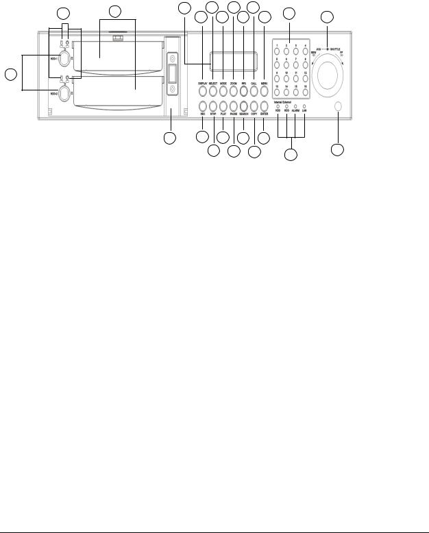
1.3Front Panel Keypads
20 |
19 |
21 |
9 |
11 |
13 |
17 |
|
|
8 |
10 |
12 |
14 |
15 |
||||
|
|
|
18
23 |
1 |
3 |
5 |
7 |
|
|
2 |
4 |
6 |
16 |
22 |
|
|
|
|
|
Keys:
1.REC: Press this key to start instant recording.
2.STOP: Press this key to stop recording and playing back.
3.PLAY: Press this key to start playing back.
4.PAUSE: Press this key to pause the playback picture.
5.SEARCH: Press this key to enter the SEARCH MENU.
6.COPY: Press this key to enter the Copy Menu.
7.ENTER: Press this key to enter items or jump to next subentry in the menu setting.
8.DISPLAY: Press this key to cycle through the display of channels and/or status bar.
4
9.SELECT: On live view, press this key to assign a camera to a multi-screen or to adjust single screen display properties. In menus, press this key to select certain features.
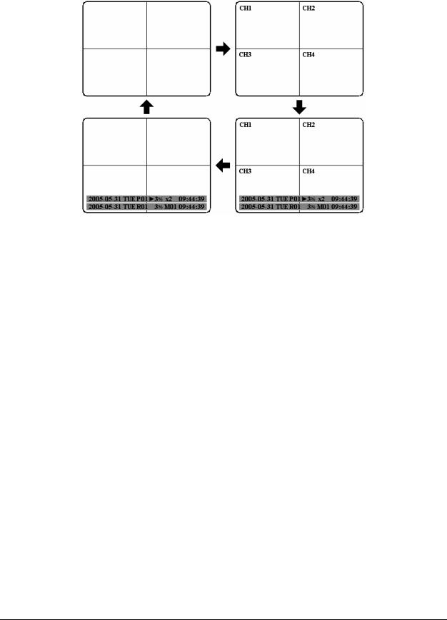
10.MODE: Switch PIP, 4, 7, 9, 10, 13 and 16 displays in Live and Playback
11.ZOOM: In full screen mode, 2x electronic zoom. Zoom screen can be moved through JOG. ENTER key changes the scroll direction between horizontal and vertical. Pressing the zoom key again switches the electronic zoom off.
In multiscreen mode: Image orientation adjustment. Use the JOG to adjust the image to the monitor type. ENTER switches between horizontal and vertical adjustment. Press the zoom key again to exit screen adjustment.
12.SEQ: Press this key to enter the auto sequential switching mode.
13.CALL: Press this key to enter and set up CALL MENU.
14.MENU: Press this key to enter/exit the Main Menu or to exit from any submenu.
5

15. Shuttle and Jog Dial
Shuttle:
In the Playback mode, turn the Shuttle dial to fast forward/rewind the video.
In the Pause mode, turn the Shuttle dial to slow forward/rewind the video.
In the event list, turn the Shuttle to change pages.
Jog Dial:
In the Pause mode, turn the Jog dial to forward/rewind the video frame by frame. In the Menu mode, turn the Jog dial to change settings and values in subentries.
16. System LEDs
LEDs for system active HDD, ALARM and LAN display.
17. Channel Key (1~16)
Press channel key (CH1~CH16) to display that channel in full screen view.
18. HDD LOCK
Turn on HDD power and prevent HDD theft.
19. Hard Disk Tray
Hard Disk holder for HDD.
20. HDD LED’s
LED’s for HDD active power (GREEN) and data reading/writing (RED).
21. LCD Panel
To display Date and Time, and other system information.
22. IR receiver
Receiver for optional infrared remote control.
23. USB slot
USB port allows you to archive video files to USB device.
6
1.4Back Panel Connections
5 |
10 |
1 |
4 |
|
|
2 |
7 |
8 |
6 |
12 |
11 |
3 |
14 |
9 |
|
|||||
|
|
15 |
|
|
|
|
|
|
|
|
|
|
13 |
|
|
|
|
POWER
1 Main Power plug: power source to AC 100~ 240V.
AUDIO
2Audio IN: Audio inputs 1~4 for recording, and it can be set to “YES” or “NO” in the RECORD SETUP MENU.
Audio OUT: Connect an audio output to a monitor or other device.
MONITOR
3MAIN MONITOR: This connector is used for the main monitor display, a number of different display modes may be selected for viewing.
4CALL MONITOR: This connector is used for the call monitor. This monitor can only display a full screen.
VIDEO IN
5 For EDR1640/1620 Series:
VIDEO OUT(1~16): Top row BNC connectors for video looping out 1~16. VIDEO IN(1~16): Bottom row BNC connectors for video input 1~16 .
7

For EDR920 Series:
VIDEO OUT(1~9): Top row BNC connectors for video looping out 1~9. VIDEO IN(1~9): Bottom row BNC connectors for video input 1~9 .
Alarm Input/Output
6 Alarm Input
ALM-INPUT: Normal open or normal close type alarm signal inputs.
The Alarm Input can be selected as normal open (N.O.) or normal close (N.C.) input in the ALARM SETUP MENU. When an alarm occurs, alarm recording will automatically start.
ALM-OUTPUT: A built-in relay offers 3 nodes which are ALM-COM (common), ALM-NO (normal open) and ALM-NC (normal close) for external use.
Note: Please check Chapter 3.4 and APPENDIX C to see other available alarm input/output functions.
LAN
7 LAN Connector: The RJ-45 network connection.
RS232
8 RS232 connector: D-Sub 9 pin connector for testing purposes only.
RS485
9RS485 connector: RJ 45 Connector for RS485 control (via EKB500 controller) and for multi Digital Video Recorder cascade.
FAN
10 FAN: Cooling FAN.
8

|
Matrix Outputs |
11 |
Matrix outputs 1~4: BNC connectors for Matrix monitor outputs 1~4. |
|
SCSI Connector |
12 |
SCSI Connector: For connecting the optional EDA800 storage expansion. |
|
Mouse |
13 |
Mouse: PS/2 connector for mouse input. |
|
S-Video |
14 |
S-Video: PS/2 connector for S-Video monitor output. |
Cascade
15Cascade is designed for connecting a number of DVRs to one monitor.
You will be allowed to view and to control as many DVRs as you prefer from the same monitor simply switching the screen using a multi-function keyboard controller.
Connect from Cascade out of the DVR to Cascade In of another with BNC
connectors. Repeat the same step for all your DVRs until you connect the last Cascade
Out to the original DVR’s Cascade In.
9
1.5Monitor Display
The status information of the cameras or machine will show up, and be located at different places on the screen.
 1. Channel tag
2. Event sign
3. Select sign
4. Play status bar
 5. Record status bar
1.Channel tag: A channel tag indicates the channel name of the screen.
2.Event sign: Event signals which are small icons with a capital letter and red background show the events on each screen. There are a total of 6 different signals:
AAlarm event. In order to show the camera video to a corresponding alarm, setting a FOCUS CAMERA in ALARM SETUP MENU is necessary.
MMotion event. Motion event only shows up when the camera’s MOTION is enabled in MOTION SETUP MENU, and the camera detects a motion.
Video loss event. Video loss event only shows when the camera’s
VVIDEOLOSS is enabled in VIDEOLOSS SETUP MENU, and the camera signal is lost.
S |
Sequence sign. Sequence sign shows up when the display is in the sequence |
||
|
mode. The last display on the screen has a “*” sign in the top-middle. The |
||
|
|||
|
|
|
sign will replace the “*” in the display when sequence occurs. |
|
|
S |
|
|
|
|
|
|
|
Note: Sequence is invalid when all cameras are showing. |
|
10
TTemperature indication. This shows if the hard drive’s temperature is overheated. Overheat is determined in HDD TEMPERATURE of WARNING SETUP MENU.
FFan fail indication. This shows when the fan fails to work normally. If you get this warning, contact technical support for assistance.
3. Select sign: You can assign a camera to a display by pressing SELECT key in live mode. Dial Jog to move the select sign to the display you would like to change camera, and then press channel key on the front panel to choose that channel. Press SELECT again to exit from this mode.
4. Play status bar: The play status bar appears in play back mode if you enable a status bar on the screen (Please see DISPLAY, 8th item of Front Panel Keypads). There are three parts that will be shown: play date, play status, and play time.
Play Date |
Play Status |
Play Time |
Play date
The date on which the video was recorded.
Play status
“PAUSE”, when the video playback is paused.
“P## >” means normal play speed on the displayed disk number;
“P## <“ means normal reverse play speed on the displayed disk number; “>> x N” means N time fast play speed;
“<< x N” means N time fast reverse play speed.
Play time
The play time at which the video is recorded. The time format depends on the time format setting in the TIME/DATE SETUP MENU.
5. Record status bar
The record status bar appears when you enable a status bar on the screen.
Current Date |
Record Status |
Event |
Current Time |
Audio Ch |
HDD/Fan Status
11

1.Current date
The current date which is set in the TIME/DATE SETUP MENU.
2.Record status
Displays current Hard Drive and record position. R01: currently recording on Disk 1
16%: currently recording at 16% of total HD position
NOTE: Percentage only indicates the physical point of recording on the Hard Drive, not the total disk space used. To review the total amount of recording time, please refer to the Disk Menu (Chapter 3.9)
3.Event
The current/last event that occurred.
4.Current time
The current time which is set in the TIME/DATE SETUP MENU.
5.Audio Ch
Displays which audio channel is currently active. This can be changed by turning the Jog wheel in the live camera mode.
6.HDD/Fan status
“No Disk”: only shows when no disk is installed or detected. “No Fan”: only shows when internal fan stops working. “HDD OT”: only shows if hard drive is over temperature.
12

Chapter
2
2.Installation
The installations described below should be made by qualified service personnel or system installers. Please check accessories in the packaging before beginning installation. Please refer to the following diagram for the basic wiring connections.
Note: Monitors and Cameras must be purchased separately.
Diagram 2.1
Diagram 2.2
13
2.1Video Connections, DVR cascading
Sample installation with maximum camera and monitor configuration:
Diagram 2.3
Cameras and monitors have to be cabled with 75 Ohm video cable, e.g. RG-59, RG-6, RG-11 and suitable BNC plugs.
Due to inappropriate absorbability, 50 Ohm coax cable (e.g. RG58), antenna cable and further types of coax cable are not suitable.
All connected video sources must provide a 1 Vpp NTSC standard video signal.
When interconnecting transmission lines (twisted pair, fibre optics, radio) to the video inputs, ensure the accurate receiver calibration.
The MAIN monitor may optionally be connected through a Y-C (S-Video) cable to achieve an improved image quality.
For local DVR operation, MAIN monitor connection is compulsory. Call and matrix monitors can be connected optionally.
ATTENTION: Make sure that there is a video signal on video input 1 upon start-up, as this input is required for video system auto detection (NTSC/PAL)!
14

DVR Cascading
The digital video recorders provide "CASCADE IN" and "CASCADE OUT" video connections.
In combination with EKB500 keyboard, up to 255 EDR1640/1620/920 can be cascaded and
administrated via one single main monitor. Cascading is effected by connecting the DVRs
“CASCADE OUT” to the “CASCADE IN” of the following DVR, while the last “CASCADE OUT” is connected to the monitor input.
Diagram 2.4
Installation with 3 cascaded EDR and EKB-500
15
2.2Audio Connection Installation
Sample installation with audio connection to video cameras providing audio output:
Diagram 2.5
The EDR1640/1620/920 DVRs provide 4 audio inputs and 1 audio output.
The inputs are designed for max. 500 mV to 10 KOhm line audio signals.
ATTENTION: The direct connection of a non-amplified microphone is not supported (a microphone amplifier is required).
The installation has to be effected with audio coax cable and RCA plugs.
The output provides a max. 500 mV to 10 KOhm line audio signal and may be connected to e.g. a monitor‘s audio input. The direct connection of (passive) speakers is not supported.
AUDIO RECORDING FUNCTIONALITY:
Audio recording is activated / deactivated in the RECORD menu for all channels.
Audio of all channels is always recorded together with (each) video and is independent of the image recording rate. There is no specific camera allocation.
During playback, use the JOG to select the requested playback channel 1~4 (active channel is indicated in playback on-screen display).
16
2.3Speed Dome Installation
Speed dome or telemetry receiver pan/tilt/zoom control is available through web browser or the optional PowerCon software if the DVR is connected to a network. Local telemetry control is provided by the optional EKB 500 keyboard.
Supported protocols: EverFocus, Pelco-D, Pelco-P, ED2200/2250
Diagram 2.6
Sample installation with 3 EPTZ1000 speed domes and EDA998
Diagram 2.7
Sample installation with 3 EPTZ1000 speed dome, EDA998 and local EKB 500 operation
Required DVR settings: RS-485 receiver address in CAMERA menu; RS-485 parameters and protocol in CONTROL menu
17

ATTENTION: Some Pelco-D / -P protocol domes and receivers require an address offset of -1. In other words, the address assigned to the dome / receiver in the DVR camera menu must be 1 below the address set in the dome / receiver itself! (i.e. DVR ID: 2, PTZ ID: 3)
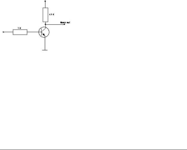
2.4Alarm Input / Output Installation
The EDR1640/1620/920 alarm inputs can be used for recording start or recording rate adjustment. Furthermore, alarm reactions such as camera switching to monitors, buzzer, e-mail and network alarm are available. An alarm output relay can be switched if required.
EDR920 provides 9 alarm inputs, EDR1640/1620 provides 16. All inputs are programmable NO/NC.
Inputs have to be switched through dry contacts.
The 4 output relays provide a dry NO/NC contact.
All settings are programmed in the ALARM menu.
Use either the 37-pin Sub-D plug or the included adaptor board for connection.
Pin assignment adaptor board |
Pin assignment sub-d board |
HOST
PIN # |
NAME |
PIN # |
NAME |
|
|
|
|
1 |
GND |
21 |
GND |
|
|
|
|
2 |
ALMIN 1 |
22 |
ALM_NC1 |
|
|
|
|
3 |
ALMIN 2 |
23 |
ALM_NO1 |
|
|
|
|
4 |
ALMIN 3 |
24 |
ALM_COM1 |
|
|
|
|
5 |
ALMIN 4 |
25 |
ALM_NC2 |
|
|
|
|
6 |
ALMIN 5 |
26 |
ALM_NO2 |
|
|
|
|
7 |
GND |
27 |
ALM_COM2 |
|
|
|
|
8 |
ALMIN 6 |
28 |
GND |
|
|
|
|
9 |
ALMIN 7 |
29 |
ALM_NC3 |
|
|
|
|
10 |
ALMIN 8 |
30 |
ALM_NO3 |
|
|
|
|
11 |
ALMIN 9 |
31 |
ALM_COM3 |
|
|
|
|
12 |
ALMIN 10 |
32 |
ALM_NC4 |
|
|
|
|
13 |
GND |
33 |
ALM_NO4 |
|
|
|
|
14 |
ALMIN 11 |
34 |
ALM_COM4 |
|
|
|
|
15 |
ALMIN 12 |
35 |
GND |
|
|
|
|
16 |
ALMIN 13 |
36 |
ALMRST |
|
|
|
|
17 |
ALMIN 14 |
37 |
REC_IN |
|
|
|
|
18 |
ALMIN 15 |
38 |
SPARE_IN |
|
|
|
|
19 |
ALMIN 16 |
39 |
DISK_FULL |
|
|
|
|
20 |
GND |
40 |
SPARE_OUT |
|
|
|
|
DVR
PIN |
NAM |
PIN |
NAM |
1 |
GN |
19 |
GN |
2 |
ALM 1 |
20 |
ALM-NC0 |
3 |
ALM 2 |
21 |
ALM-NO |
4 |
ALM 3 |
22 |
ALM-COM0 |
5 |
ALM 4 |
23 |
ALM-NC1 |
6 |
ALM 5 |
24 |
ALM-NO |
7 |
ALM 6 |
25 |
ALM-COM1 |
8 |
ALM 7 |
26 |
ALM-NC2 |
9 |
ALM 8 |
27 |
ALM-NO |
10 |
ALM 9 |
28 |
ALM-COM2 |
11 |
ALM 10 |
29 |
ALM-NC3 |
12 |
ALM 11 |
30 |
ALM-NO |
13 |
ALM 12 |
31 |
ALM-COM3 |
14 |
ALM 13 |
32 |
ALMRSTO |
15 |
ALM 14 |
33 |
REC |
16 |
ALM 15 |
34 |
GIN1 |
17 |
ALM 16 |
35 |
DISKFULL |
18 |
GN |
36 |
GO |
18
Descriptions:
ALMINxx: Alarm input xx (1~16)
GND: common ground for alarm inputs
ALM_COMx: output relay x , contact root
ALM_NOx: output relay x , NO contact
ALM_NCx: output relay x , NC contact
ALMRST: Alarm reset, control input for alarm reset, for dry NO contact towards GND
DISKFULL: OC output contact for signal HDD full, switches to GND
REC_IN: Control contact for recording start
SPARE_IN / OUT: System error output. TTL-level 5VDC indicates "System Okay" status. The contact will switch to open state, if one (ore more) of below listed events appears:
a)HDD full (If overwrite mode in RECORD menu is set to STOP)
b)No HDD
c)Over-temperature HDD
d)Power Loss
e)Cooler fan fault
f)Video Loss
g)Record off
Output level:
HIGH (5 V DC): System okay
Open state: System error
19
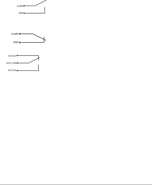
SPARE_IN: N.O. Control input for playback function, playback is active as long contact is
closed.
NO contact alarm input connection:
NC contact alarm input connection:
Output relay in idle state:
20
 Loading...