


Volume
1
Instruction Manual
EDR810H/EDR810M
EDR410H/EDR410M

E V E R F O C U S E L E C T R O N I C S C O R P O R A T I O N
EDR 810H/810M/410H/410M
Instruction Guide
2005 EverFocus Electronics Corp
www.everfocus.com
All rights reserved. No part of the contents of this manual may be reproduced or transmitted in any form or by any means without written permission of the Everfocus Electronics Corporation.
Release Date: April 2009
QuickTime is a registered trademark of the Apple Computer, Inc. Windows is a registered trademark of the Microsoft Corporation.
Linksys is a registered trademark of the Linksys Corporation. D-Link is a registered trademark of the D-Link Corporation.
DynDNS is a registered trademark of the DynDNS.org Corporation.
Other product and company names mentioned herein may be the trademarks of their respective owners.
Federal Communication Commission Interference Statement
This equipment has been tested and found to comply with the limits for a Class B digital device, pursuant to Part 15 of the FCC Rules. These limits are designed to provide reasonable protection against harmful interference in a residential installation. This equipment generates, uses and can radiate radio frequency energy and, if not installed and used in accordance with the instructions, may cause harmful interference to radio communications. However, there is no guarantee that interference will not occur in a particular installation. If this equipment does cause harmful interference to radio or television reception, which can be determined by turning the equipment off and on, the user is encouraged to try to correct the interference by one of the following measures :
•Reorient or relocate the receiving antenna.
•Increase the separation between the equipment and receiver.
•Connect the equipment into an outlet on a circuit different from that to which the receiver is connected.
•Consult the dealer or an experienced radio/TV technician for help. FCC Caution: Any changes
or modifications not expressly approved by the party responsible for compliance could void the users’s authority to operate this equipment. This device complies with Part 15 of the FCC Rules.
Operation is subject to the following two conditions: (1) This device may not cause harmful interference, and (2) this device must accept any interference received, including interference that may cause undesired operation. This device and its antenna(s) must not be co-located or operating in conjunction with any other antenna or transmitter.
TABLE OF CONTENTS |
|
1. PRODUCT OVERVIEW ....................................................................................................... |
12 |
1.1 FEATURES ............................................................................................................................ |
12 |
1.2 SPECIFICATIONS ................................................................................................................... |
13 |
1.3 FRONT PANEL KEYPADS ....................................................................................................... |
14 |
1.4 BACK PANEL CONNECTIONS ................................................................................................ |
17 |
1.5 MONITOR DISPLAY .............................................................................................................. |
20 |
2. INSTALLATION .................................................................................................................... |
24 |
2.1 BASIC WIRING INSTRUCTIONS ............................................................................................. |
25 |
2.2 HARD DISK DRIVE INSTALLATION ....................................................................................... |
27 |
2.3 FINAL INSTALL PROCESS ...................................................................................................... |
27 |
2.4 QUICK INSTALLATION GUIDE FOR EDR810M & EDR410M ONLY......................... |
28 |
3. DVR MENU SETUP .............................................................................................................. |
33 |
3.1 TIME/DATE SETUP MENU..................................................................................................... |
34 |
3.2 CAMERA SETUP MENU......................................................................................................... |
38 |
3.3 RECORD SETUP MENU ......................................................................................................... |
42 |
3.4 ALARM SETUP MENU ........................................................................................................... |
44 |
3.5 MOTION SETUP MENU ......................................................................................................... |
47 |
3.6 VIDEOLOSS SETUP MENU................................................................................................. |
50 |
3.7 NETWORK SETUP MENU ...................................................................................................... |
52 |
3.7.1 CONFIG .............................................................................................................................. |
52 |
3.7.2 ALARM NETWORK .......................................................................................................... |
55 |
3.7.3 EMAIL................................................................................................................................. |
56 |
3.7.4 PASSWORD ........................................................................................................................ |
57 |
3.7.5 WIRELESS .......................................................................................................................... |
58 |
3.7.6 PPPOE .................................................................................................................................. |
60 |
3.7.7 DDNS .................................................................................................................................. |
61 |
3.7.8 GPS ...................................................................................................................................... |
63 |
3.8 SCHEDULE SETUP MENU...................................................................................................... |
64 |
3.9 DISK SETUP MENU............................................................................................................... |
66 |
3.10 CONTROL SETUP MENU ..................................................................................................... |
68 |
3.11 WARNING SETUP MENU ..................................................................................................... |
70 |
3.11.1 FAN FAULT....................................................................................................................... |
70 |
3.11.2 HDD TEMP ....................................................................................................................... |
71 |
3.11.3 NO HDD............................................................................................................................. |
73 |
3.11.4 HDD FULL ........................................................................................................................ |
74 |
3.12 SYSTEM SETUP MENU........................................................................................................ |
76 |
4. RECORDING OVERVIEW .................................................................................................. |
79 |
4.1 INSTANT (N) RECORDING SETUP.......................................................................................... |
79 |
4.2 SCHEDULE RECORDING SETUP............................................................................................. |
80 |
4.3 EVENT RECORDING SETUP ................................................................................................... |
81 |
5. PLAYBACK OVERVIEW..................................................................................................... |
84 |
5.1 BASIC PLAYBACK ................................................................................................................ |
84 |
5.2 SEARCH PLAYBACK ............................................................................................................. |
87 |
6. COPYING VIDEO ................................................................................................................. |
90 |
6.1 VIEWING A COPIED FILE ...................................................................................................... |
92 |
7. CALL OVERVIEW................................................................................................................ |
93 |
8. SCREEN DISPLAY SETTING & MODE ........................................................................... |
94 |
8.1 MODE BUTTON .................................................................................................................... |
95 |
9. UPGRADE FIRMWARE....................................................................................................... |
96 |
10. NETWORKING OVERVIEW ............................................................................................ |
97 |
10.1 INTRODUCTION TO TCP/IP................................................................................................. |
97 |
10.2 SUBNET MASKS ................................................................................................................. |
97 |
10.3 GATEWAY ADDRESS ........................................................................................................... |
98 |
10.4 VIRTUAL PORTS ................................................................................................................. |
98 |
10.5 PRE-INSTALLATION ............................................................................................................ |
98 |
10.6 WHAT TYPE OF NETWORK CONNECTION DO YOU HAVE?.................................................. |
100 |
10.7 SIMPLE ONE TO ONE CONNECTION .................................................................................. |
101 |
10.8 DIRECT HIGH SPEED MODEM CONNECTION..................................................................... |
107 |
10.9 ROUTER OR LAN CONNECTION ....................................................................................... |
109 |
11. LINKSYS PORT FORWARDING..................................................................................... |
112 |
12. D-LINK PORT FORWARDING........................................................................................ |
116 |
13. EVERFOCUS DDNS SETUP............................................................................................ |
120 |
14. VIEWING THROUGH INTERNET EXPLORER......................................................... |
122 |
14.1 SEARCH......................................................................................................................... |
128 |
14.1.1 SEARCH BY TIME .............................................................................................................. |
128 |
14.1.2 SEARCH BY EVENT ......................................................................................................... |
129 |
14.2 PTZ CONTROL.................................................................................................................. |
130 |
14.3 REMOTE ARCHIVE...................................................................................................... |
131 |
14.4 REMOTE CONFIGURATION................................................................................................ |
136 |
15. INTERFACE SPECIFICATIONS .................................................................................... |
143 |
15.1 TRANSMISSION SETTING .................................................................................................. |
143 |
15.2 REMOTE CONTROL PROTOCOL......................................................................................... |
144 |
APPENDIX A: REMOTE CONTROL .................................................................................. |
147 |
APPENDIX B: ALARM BOARD CONFIGURATION........................................................ |
148 |
TROUBLESHOOTING........................................................................................................... |
150 |

Safety Warning
WARNING
TO REDUCE RISK OF FIRE OR ELECTRIC SHOCK,
DO NOT EXPOSE THIS APPLIANCE TO RAIN OR MOISTURE.
CAUTION
DO NOT REMOVE COVER. NO USER SERVICEABLE PARTS INSIDE.
Note:
This equipment has been tested and found to comply with the limits for a Class A digital device,
The changes or modifications not expressly approved by the party responsible for compliance could void the user's authority to operate the equipment.
Note:
This is a class A product. In a domestic environment this product may cause radio interference, in which case the user may be required to take adequate measures.
Notice:
The information in this manual was current when published.
The manufacturer reserves the right to revise and improve its products.
All specifications are therefore subject to change without notice.
Safety Precautions
Refer all work related to the installation of this product to qualified service personnel or system installers.
Do not block the ventilation opening or slots on the cover.
Do not drop metallic parts through slots. This could permanently damage the appliance. Turn the power off immediately and contact qualified service personnel for service.
Do not attempt to disassemble the appliance. To prevent electric shock, do not remove screws or covers. There are no user-serviceable parts inside. Contact qualified service personnel for maintenance. Handle the appliance with care. Do not strike or shake, as this may damage the appliance.
Do not expose the appliance to water or moisture, not try to operate it in wet areas. Do take immediate action if the appliance becomes wet. Turn the power off and refer servicing to qualified service personnel. Moisture may damage the appliance and also cause electric shock.
Do not use strong or abrasive detergents when cleaning the appliance body. Use a dry cloth to clean the appliance when it is dirty. When the dirt is hard to remove, use a mild detergent and wipe gently.
Do not overload outlets and extension cords as this may result in a risk of fire or electric shock.
Do not operate the appliance beyond its specified temperature, humidity or power source ratings. Do not use the appliance in an extreme environment
where high temperature or high humidity exists. Use the appliance at temperature within indoor type DVR for 32oF ~ +104oF and a humidity below 90%. The input power source for this appliance is AC100~240V.
Safety Precautions
Read Instruction
All the safety and operating instructions should be read before the unit is operated.
Retain Instructions
The safety and operating instructions should be retained for future reference.
Heed Warnings
All warnings on the unit and in the operating instructions should be adhered to.
Follow Instructions
All operating and use instructions should be followed.
Cleaning
Unplug the unit from the outlet before cleaning. Do not use liquid cleaners or aerosol cleaners. Use a damp cloth for cleaning
Attachments
Do not use attachment not recommended by the product manufacturer as they may cause hazards.
Water and Moisture
Do not use this unit near water-for example, near a bath tub, wash bowl, kitchen sink, or laundry tub, in a wet basement, near a swimming pool, in an unprotected outdoor installation, or any area which is classified as a wet location.
Servicing
Do not attempt to service this unit by yourself as opening or removing covers may expose you to dangerous voltage or other hazards. Refer all servicing to qualified service personnel.
Power Cord Protection
Power supply cords should be routed so that they are not likely to be walked on or pinched by items placed upon or against them, playing particular attention to cords and plugs, convenience receptacles, and the point where they exit from the appliance.
Object and Liquid Entry
Never push objects of any kind into this unit through openings as they may touch dangerous voltage points or short-out parts that could result in a fire or electric shock. Never spill liquid of any kind on the unit.
Chapter
1
1. Product Overview
EDR810/410 DVRs are the industry’s first full-featured digital video recorder designed specifically for use within the security industry. EDR810/410 DVRs incorporates all the benefits of digital video recording, is simple to install, and operates just like a VCR. Highly efficient compression technology and superior resolution of recorded images make the Digital Video Recorder stand out from the competition as the best choice for security surveillance.
1.1 Features
Duplex Operation for Recording & Playback
Built-in MPEG4 Codec with Configurable Quality
Variable Recording Speeds up to 60/50 Images per second for NTSC/PAL
Audio Recording Capabilities
Motion Detection Capabilities
One 3.5” Hard Disk with Hot-Swap Tray for Internal Storage
Ethernet Interface for Remote Network Viewing
Optional Wireless LAN Interface for Data Transmission
RS485 for Remote Control
Shuttle/Jog Dial for Picture-by-Picture or Fast/Slow Viewing
Easy-to-use Control Panel with Common VCR and Multiplexer Functions
On-Screen Menus Operations with Multi-Language Support
Real-Time Live Display for all Cameras
Easy archiving of video and Remote Viewer through USB port
Remote configuration function
Remote Firmware Upgrade function
Motion detection function can be scheduled according to user’s setting
For mobile models (ED810M/410M), GPS data can be sent out to receiver, for user to orientate the exact position
1.2 Specifications
Video format |
NTSC or PAL |
|
Video input |
4/8 camera inputs (BNC), 1Vp-p/75ohm |
|
|
1 BNC video out (1Vp-p/75ohm) for Main Monitor |
|
Video output |
1 BNC video out (1Vp-p/75ohm) for Call Monitor |
|
|
4 BNC outputs (1Vp-p/75ohm) for Looping (4 Channels only) |
|
Video compression |
MPEG4 |
|
Recording resolution |
720x240, 720x480 or 360x240 for NTSC |
|
|
720x288, 720x576 or 360x288 for PAL |
|
Video display |
Full, 4, 7, and 9 screen view for Live and Playback |
|
PIP and 2x2 Zoom for Playback only |
||
|
||
Alarm inputs |
4/8 Alarm Inputs |
|
Alarm outputs |
1 Alarm Output |
|
Hard disk storage |
One Hot-Swappable 3.5” IDE or SATA Hard Disk |
|
(2.5” hard disk available for mobile models) |
||
|
||
Recording rate |
Up to 120/100 Images per second for NTSC/PAL |
|
Recording mode |
Continuous, Schedule, Event (Motion and Alarm) recording |
|
|
|
|
Playback rate |
Up to 60/50 Images per second for NTSC/PAL |
|
Playback search |
By Date/Time or Event (Motion, Video Loss, Alarm) |
|
Playback options |
Play, Pause, Stop, Fast Fwd, Fast Rev, Slow Fwd, Slow Rev |
|
Motion detection |
Yes, with configurable detection grid & sensitivity per camera |
|
Video Loss detection |
Yes |
|
Event Log |
Yes |
|
Setup |
Menu Driven On Screen Display |
|
User input device |
Front panel keypad with Shuttle/Jog, IR Remote Control, |
|
EKB500 Keyboard (optional) |
||
|
||
Timer |
Built-in real time clock with Watch Dog function and Auto Time |
|
Synchronization through NTP server |
||
|
||
Title |
12-characters title for each camera |
|
Ethernet |
RJ45 connectors for network communication |
|
Archive |
USB port for flash memory or external DVD drive |
|
RS-232 |
9-pin female connector for testing purpose only |
|
RS-485 |
for Keyboard or PTZ connection |
|
Audio |
1 set of stereo inputs, 1 set of stereo outputs |
|
Power rate |
12~24 VDC |
|
Dimensions |
Inches: 11.7 (L) x 8.3 (W) x 3.5 (H) |
|
Millimeters: 296.9 (L) x 211.1 (W) x 88.9 (H) |
||
|
||
Weight |
4 kg (approximately 8.8 lbs) |
|
Operating |
0oC ~ 40oC (32 ~104 ) |
|
temperature |
||
|
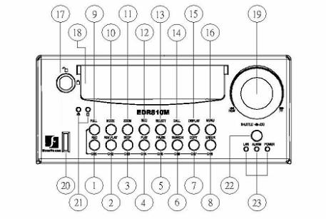
1.3 Front Panel Keypads
Keys:
○1 ~ ○8 Channel Key: Press FULL+Channel Key (CH1~CH8) to display video image in the full screen format; the picture of the corresponding channel will fill the whole screen.
○1 CH1 / REC: Press this key to start instant recording.
○2 CH2 / REV. PLAY: Reverse Play Back.
○3 CH3 / STOP: Press this key to stop recording and playing back.
○4 CH4 / PLAY: Play Back.
○5 CH5 / PAUSE: Press this key to pause the playback picture.
○6 CH6 / SEARCH: Press this key to enter the SEARCH MENU.
○7 CH 7 / COPY: Press this key to enter the COPY MENU. If pressed while in playback mode, it is also used to bookmark copy time.
○8 CH8 / ENTER: Press this key to enter items, or jump to next subentry in the menu setting.
○9 FULL: Press this key and channel Key at the same time to switch to full screen in both live mode and play back mode. Press “MODE” to exit full screen.
○10 MODE: Switch PIP (Live only), 4, 7 and 9 displays in Live and Playback modes.
○11 ZOOM: In full screen mode, 2x electronic zoom. Zoom screen can be moved through JOG.
ENTER key changes the direction. Press the zoom key again to switch the electronic zoom off.
In multiscreen mode: Screen adjustment. Use the JOG to adjust the image to the fit the monitor. ENTER switches between horizontal and vertical adjustment. Press the zoom key again to switch the screen adjustment off.
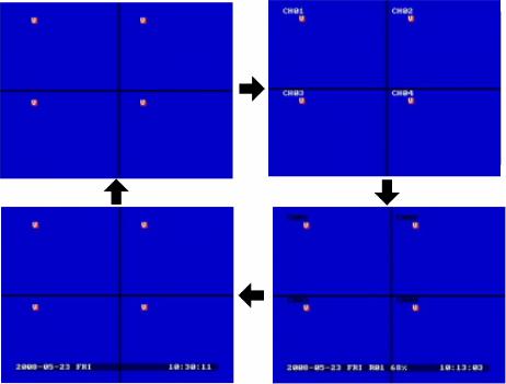
○12 SEQ: Press this key to enter the auto sequential switching mode.
○13 SELECT: In multi-screen, press this key to assign cameras to different screens; in single
screen, use it to adjust display properties. In menus, press this key to select certain features.
○14 CALL: Press this key to enter and set up CALL MENU.
○15 DISPLAY: Press this key to switch display of channels and/or status bar.

○16
○17
○18
○19
○20
○21
○22
○23
MENU: Press this key to enter or exit MAIN SETUP MENU or to exit from any submenu.
HDD Lock: Keeps HDD in place and turns on HDD power.
Hard Disk Tray: Hard Disk holder for HDD.
Shuttle and Jog Dial
Shuttle:
In the Playback mode, turn the Shuttle dial to fast forward/rewind the video.
In the Pause mode, turn the Shuttle dial to slow forward/rewind the video.
In the event list, turn the Shuttle to change pages.
Jog Dial:
In the Menu mode, turn the Jog dial to change settings and values in subentries. In the Pause mode, turn the Jog dial to forward/rewind the video frame by frame.
USB Slot: USB port allows you to archive video files or upgrade the DVR software.
HDD LEDs: LEDs for HDD active power (GREEN) and data reading /writing (YELLOW).
Remote Control: Receiver for IR remote control.
System LEDs: LEDs for system active LAN, ALARM and POWER display.

1.4 Back Panel Connections
Back panel of 810H |
Back panel of 810M |
Back panel of 410H |
Back panel of 410M |

POWER
○1 |
Main Power plug: Connect the DC 12~ 24V power source to adapter for AC 100~ 240V. |
○2 |
Audio IN: Audio input for recording, and it can be set to “YES” or “NO” in the RECORD |
|
SETUP MENU. |
|
Audio OUT: Connect an audio output to a monitor or other device. |
MONITOR |
|
○3 |
MAIN MONITOR: This connector is used for the main monitor display, a number of |
|
different display modes may be selected for viewing. |
○4 |
CALL MONITOR: This connector is used for the call monitor. This monitor can only |
|
display a full screen picture. |
VIDEO CONNECTIONS
○5 For EDR810 Series:
VIDEO IN(1~8): BNC video inputs.
For EDR410 Series:
VIDEO IN(1~4): BNC video inputs
VIDEO OUT(1~4): BNC loop-through outputs
ALARM INPUT/OUTPUT
○6 ALM-INPUT: Normal open or normal close type alarm signal inputs.
The Alarm Input can be selected as Normal Open (N.O.), Normal Close (N.C.), N.C. TRANS., or N.O, TRANS input in the ALARM SETUP MENU.
When an alarm occurs, alarm recording will automatically start.
ALM-OUTPUT: A built-in relay offers 3 nodes which are ALM-COM (common), ALM-NO (normal open) and ALM-NC (normal close) for external use. Note: Please check APPENDIX C to see other available alarm input/output functions.

LAN
○7 LAN Connector: RJ-45 network connection.
RS232
○8 RS232 connector: D-Sub 9-pin connector to RS232 ports for testing purpose ONLY.
RS485
○9 RS485 connector: RJ 45 Connector to cascade/control multi Digital Video Recorders.
Remote
○10 Remote Control: Remote control port allows for an extension wire with an IR receiver instead of the IR receiver on the front panel.
Note: The IR receiver extension line (10m) must be purchased separately.
Wireless LAN
○11 Antenna: Integrated IEEE 802.11b/g wireless LAN capabilities. The antenna port is for wireless network antenna use (For EDR 410M and 810M only).
Fan
○12 Fan: Cooling fan.
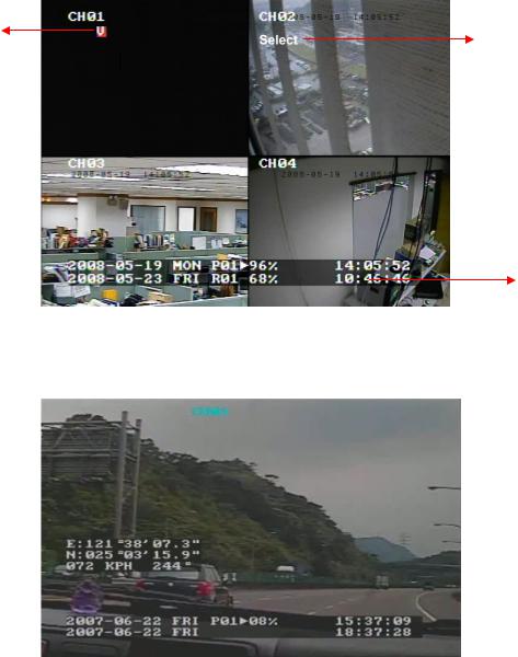
1.5 Monitor Display
The status information of the cameras or machine will show up, and be located at different places on the screen.
 1. Channel tag
2. Event sign
3. Select sign
 4. Play status bar 5. Record status bar
For mobile model only:
6. GPS  orientation

○1 Channel tag: A channel tag indicates the channel name of the screen.
○2 Event sign: Event signals which are small icons with a capital letter and red background show
the events on each screen. There are a total of 6 different signals:
A |
|
Alarm event. |
|
Alarm event shows on a channel if an ALARM is enabled for that camera in the ALARM |
|
|
||
|
SETUP MENU and an alarm is triggered. |
|
|
|
Motion event. |
M |
|
|
|
|
Motion event only shows up when the camera’s MOTION is enabled in MOTION SETUP |
|
|
|
|
|
MENU and the camera detects movement. |
|
|
Video loss event. |
V |
|
|
|
Video loss event only shows when the camera’s VIDEOLOSS is enabled in VIDEOLOSS |
|
|
||
|
SETUP MENU and the camera signal is lost. |
|
|
|
Sequence sign. |
S |
|
|
|
Sequence sign shows up when the display is in sequence mode. |
|
|
||
The last display on the screen has a “*” sign in the top-middle. The S sign will replace the “*” in the display when sequence occurs.
Note: Sequence cannot be activated when the multi-screen display is showing all cameras.
Temperature indication.
TThis shows if the hard drive’s temperature is overheated.
Overheat temperature is determined in HDD TEMPERATURE of WARNING SETUP MENU.
FFan fail indication.
This shows when the fan fails to work normally. If you get this warning, contact technical support for assistance.
○3 Select sign: You can assign a camera to a display by pressing SELECT key in live mode.
Dial Jog to move the select sign to the display you would like to change, and then press the desired channel key from the front panel to move that channel to that screen. Press SELECT again to exit from this mode.
○4 Play status bar: The play status bar appears in play back mode if the status bar is enabled (see
DISPLAY, 8th item of Front Panel Keypads). There are three parts that will be shown: play date, play status, and play time.
Play Date |
Play Status |
Play Time |
1.Play date
The date on which the video was recorded.
2.Play status
“PAUSE”, when the video playback is paused.
“P## >” means normal play speed on the displayed disk number;
“P## <“ means normal reverse play speed on the displayed disk number;
“##%” shows the position on the Hard Drive; “>> x N” means N time fast play speed;
“<< x N” means N time fast reverse play speed.
3.Play time
The play time at which the video is recorded. The time format depends on the setting in the
TIME/DATE SETUP MENU.
○5 Record status bar
The record status bar appears when you enable a status bar on the screen. There are four parts: current date, record status, event, and current time.
Current Date |
Record Status |
Event |
Current Time |
HDD/Fan Status
1.Current date
The current date which is set in the TIME/DATE SETUP MENU.
2.Record status
Displays current Hard Drive and record position. R01: currently recording on Disk 1
16%: currently recording at 16% of total HD position
NOTE: Percentage only indicates the physical point of recording on the Hard Drive, not the total disk space used. To review the total amount of recording time, please refer to the Disk Menu (Chapter 3.9)
3.Event
The current/last event that occurred.
4.Current time
The current time, which can be set in the TIME/DATE SETUP MENU.
5.HDD/FAN status
“No Disk”: only shows when no disk is installed or detected. “No Fan”: only shows when internal fan stops working. “HDD OT”: only shows if hard drive is over temperature.
○6 GPS orientation
When GPS data is sent out to receiver, the exact position will be located by showing vehicle’s longitude and latitude.
Chapter
2
2. Installation
The installations described below should be done by qualified service personnel or system installers.
I) PACKING
Please check accessories in the packing before the installation.
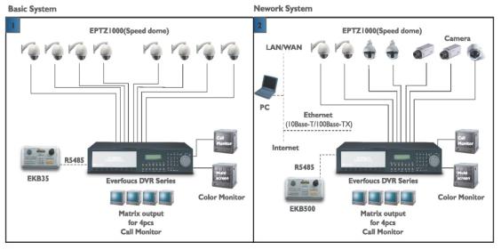
II) SYSTEM FLOORPLAN
Please refer to the following diagrams for the system connections.
Note: Monitor and Camera must be purchased separately.
Diagram 2.1
2.1 Basic Wiring Instructions
Please refer to diagram 2.1 to assist you with this portion of the installation.
1.Power
Connect the power source or adapter into the power socket.
2.Cameras
Connect each cameras video output to the video inputs on the digital video recorder.
Note: At least one camera must be connected before the system is running for the auto detection of video standard to take effect.
3.Audio Input
The camera audio output or Microphone is connected to the audio input terminal at the rear panel.
4.Audio Output
Connect the speaker or other audio listening devices to the audio output terminal on the back of the digital video recorder.
5.Ethernet
The digital video recorder may be viewed from a PC via the LAN connector using a RJ45 Ethernet cable.
6.RS485
The digital video recorder can be controlled from an EKB500 keyboard via RS485.
Note: This can be done using a RJ45-to-serial cable.
7.Main Monitor
Connect a monitor to the main monitor output connector. The main monitor displays live or recorded cameras in any available format.
Note: The main monitor must be connected in order to make configuration changes, enter the main menu, or do a playback at the machine.
8.Call Monitors
Connect the call monitor output connectors to a call monitor. The call monitor display selected live cameras in full screen format.
Note: The call monitor will only display one full screen camera at a time.
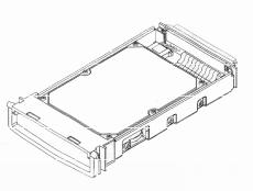
2.2 Hard Disk Drive Installation
The first step in installing the hard drive is to insert the hard drive sleeve into the machine. The hard disk drive default setting is initially set to master. The second step is to insert the key provided and turn the tray key to the lock position. If this process is ignored the hard disk drive will not be detected.
Note: If the Hard Disk Drive is not locked in with the key, HDD LED will not light up and the DVR will not go into record mode. This is because the Hard Drive is not being recognized.
Note: After powering on the DVR, it will start to load system. It takes a while to complete loading system, during this time, please do not install or remove the hard disk. No action is recommended while the machine is loading system.
Diagram 2.2 shows 3.5“ Hard Drive
2.3 Final Install Process
Once you have completed the basic wiring installation and the hard disk drive installation you are ready to turn on the DVR. Simply plug the power source you installed earlier. The POWER LED lights will light up if power is normal. The next step is to set up the menu options for the DVR.
2.4 QUICK INSTALLATION GUIDE FOR EDR810M & EDR410M ONLY
The EDR810M & EDR410M are the full-featured digital video recorders designed specifically for use in mobile applications. Please refer to the following Quick Installation Guide for installing EDR810M or EDR410M into mobile applications such as buses, cars and police cruisers.
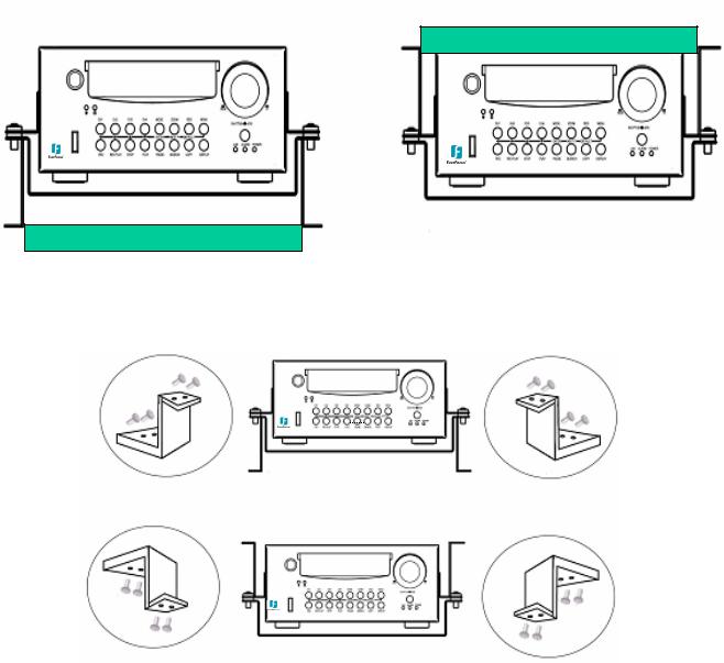
The DVR can be mounted horizontally (suspend or support mounted).
Support
Interface
EDR410M
EDR410M
Interface
Suspend
Show all the possible ways to mount the DVR.
Use the two Z-brackets supplied to mount it in any ways shown.
EDSR40
Support
EDSR400M
Suspend
Quick

Unpack Everything
Make sure you have everything you need before you begin the installation.
Equipment Required
The following tools may help you to complete the installation:
•Drill
•Screwdrivers
•Wire cutters
Choosing the Location Choose a location for installation that:
•Provides convenient access for installing or removing the hard drive
•Allows air to flow around the fan vents. Inadequate or improper air flow can impede proper
operation of the unit
Avoid any location for installation:
•That is subject to high vibration
•That is subject to high sunlight levels
•That is subject to drenched of the rain
•Where passengers can interfere with unit
•Next to a heater duct
The following table lists the recommended location options.
Location |
Convenient operation |
Easy to install |
Low vibration |
Good air flow |
Bottom of glove boxhorizontal mount |
Yes |
Yes |
Yes |
Yes |
|
||||
|
|
|
|
|
Bottom of passenger seat next to the driver |
NO |
Yes |
Yes |
Yes |
|
|
|
|
|
Underneath bulkhead-horizontal mount |
Yes |
Yes |
NO |
Yes |
|
|
|
|
|
Front of bulkhead-horizontal mount |
Yes |
Yes |
Yes |
Yes |
|
||||
|
|
|
|
|
Beside deriver seat-horizontal mount |
Yes |
Yes |
Yes |
Yes |
Caution: Do not install the DVR on the floor or on the transmission access hatch. These locations have the highest levels of vibration and may be subject to water damage.
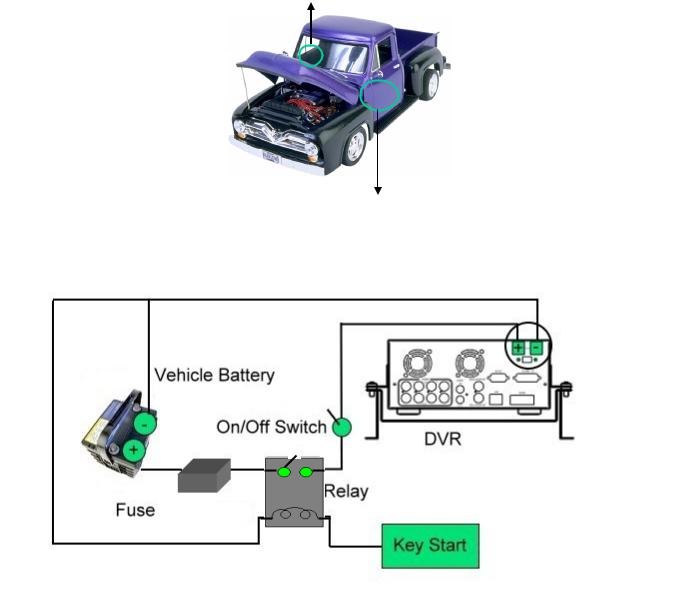
Possible Installation Locations Inside the Automobile Vehicle: Truck
Glove box (inside or underneath)
Drive seat (between seat and wall) or Passenger seat (underneath)
(Users are suggested to use “support” for mounting option)
Show the wiring on the wiring harness that connects to the electrical system.
(24 V)
(5 A)
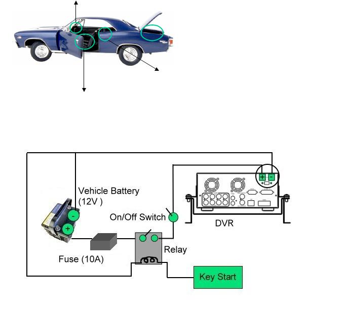
Possible Installation Locations Inside the Automobile Vehicle: TOYOTA CAMRY
Glove box (inside or underneath)
 Trunk (Users are suggested to use “suspend” for mounting option)
Passenger seat (underneath)
Drive seat (between seat and wall)
Show the wiring on the wiring harness that connects to the electrical system.
 Loading...