


User Manual
ECOR 264 Digital Video Recorder
ECOR 264-8/4 F2
(8/4-channel DVR ECOR 264 without DVD+RW)
ECOR 264-8/4 D2
(8/4-channel DVR ECOR 264 with DVD+RW)

E V E R F O C U S E L E C T R O N I C S C O R P O R A T I O N
ECOR 264 F2/D2 DVR Series
Instruction Manual
2010 EverFocus Electronics Corp
www.everfocus.com
All rights reserved. No part of the contents of this manual may be reproduced or transmitted in any form or by any means without written permission of the Everfocus Electronics Corporation.
Release Date: September 2010
QuickTime is a registered trademark of the Apple Computer, Inc. Windows is a registered trademark of the Microsoft Corporation.
Linksys is a registered trademark of the Linksys Corporation. D-Link is a registered trademark of the D-Link Corporation.
DynDNS is a registered trademark of the DynDNS.org Corporation.
Other product and company names mentioned herein may be the trademarks of their respective owners.

Safety Precautions
Refer all work related to the installation of this product to qualified service personnel or system installers.
Do not block the ventilation opening or slots on the cover.
Do not drop metallic parts through slots. This could permanently damage the appliance. Turn the power off immediately and contact qualified service personnel for service.
Do not attempt to disassemble the appliance. To prevent electric shock, do not remove screws or covers. There are no user-serviceable parts inside. Contact qualified service personnel for maintenance. Handle the appliance with care. Do not strike or shake, as this may damage the appliance.
Do not expose the appliance to water or moisture, not try to operate it in wet areas. Do take immediate action if the appliance becomes wet. Turn the power off and refer servicing to qualified service personnel. Moisture may damage the appliance and also cause electric shock.
Do not use strong or abrasive detergents when cleaning the appliance body. Use a dry cloth to clean the appliance when it is dirty. When the dirt is hard to remove, use a mild detergent and wipe gently.
Do not overload outlets and extension cords as this may result in a risk of fire or electric shock.
Do not operate the appliance beyond its specified temperature, humidity or power source ratings. Do not use the appliance in an extreme environment where high temperature or high humidity exists. Use the appliance at temperature within indoor type DVR for 0°C~40°C (32°F~104°F) and at relative humidity between 20%~80%. The input power source for this device is 12 VDC with external power supply 100~240VAC.
ATTENTION! This is a class A product which may cause radio interference in a domestic environment; in this case, the user may be urged to take adequate measures.
This Product is RoHS compliant.
Your EverFocus product is designed and manufactured with high quality materials and components which can be recycled and reused. This symbol means that electrical and electronic equipment, at their end-of-life, should be disposed of separately from your household waste.
Please, dispose of this equipment at your local community waste collection/recycling centre.
In the European Union there are separate collection systems for used electrical and electronic product.
Please, help us to conserve the environment we live in!
Ihr EverFocus Produkt wurde entwickelt und hergestellt mit qualitativ hochwertigen Materialien und Komponenten, die recycelt und wieder verwendet werden können.
Dieses Symbol bedeutet, dass elektrische und elektronische Geräte am Ende ihrer Nutzungsdauer vom Hausmüll getrennt entsorgt werden sollen.
Bitte entsorgen Sie dieses Gerät bei Ihrer örtlichen kommunalen Sammelstelle oder im Recycling Center.
Helfen Sie uns bitte, die Umwelt zu erhalten, in der wir leben!
The information in this manual was current upon publication. The manufacturer reserves the right to revise and improve his products. Therefore, all specifications are subject to change without prior notice. Manufacturer is not responsible for misprints or typographical errors. Please read this manual carefully before installing and using this unit. Be sure to keep it handy for later reference.
ii

TABLE OF CONTENTS
1 |
PRODUCT OVERVIEW........................................................................................................................ |
1 |
|
1.1 |
FEATURES .......................................................................................................................................................... |
1 |
|
1.2 |
PACKAGE CONTENTS........................................................................................................................................... |
2 |
|
1.3 |
SPECIFICATIONS ................................................................................................................................................. |
3 |
|
1.4 |
FRONT PANEL ..................................................................................................................................................... |
5 |
|
1.5 |
REAR PANEL ....................................................................................................................................................... |
7 |
|
1.6 |
VIDEO INPUT / OUTPUT INSTALLATION................................................................................................................... |
8 |
|
1.6.1 |
Video inputs.............................................................................................................................................................. |
8 |
|
1.6.2 |
Monitor output .......................................................................................................................................................... |
8 |
|
1.7 |
ALARM CONTACT INSTALLATION ........................................................................................................................... |
9 |
|
1.7.1 |
Alarm Input Contacts................................................................................................................................................ |
9 |
|
1.7.2 |
Alarm Output Relay .................................................................................................................................................. |
9 |
|
1.8 |
RS-485 KEYBOARD / PTZ INSTALLATION ............................................................................................................ |
10 |
|
1.8.1 |
General RS-485 bus installation............................................................................................................................. |
10 |
|
1.8.2 |
RS-485 socket pin assignment............................................................................................................................... |
11 |
|
1.8.3 |
EKB-500 connection with network patch cable ...................................................................................................... |
11 |
|
1.8.4 |
EKB-500 connection to several DVRs.................................................................................................................... |
11 |
|
1.8.5 |
Speed Dome Installation ........................................................................................................................................ |
12 |
|
1.9 |
USB MOUSE INSTALLATION................................................................................................................................ |
12 |
|
1.10 |
NETWORK CONNECTION ................................................................................................................................. |
13 |
|
1.10.1 |
Direct PC Connection through Crossover Network Cable...................................................................................... |
13 |
|
1.10.2 |
Network Connection through Patch Cable ............................................................................................................. |
13 |
|
1.11 |
FINAL INSTALL PROCESS ................................................................................................................................ |
14 |
|
2 |
MOUSE AND FRONT PANEL OPERATION ..................................................................................... |
15 |
|
2.1 |
GENERAL USB MOUSE OPERATION ................................................................................................................... |
15 |
|
2.1.1 |
How to select a channel ......................................................................................................................................... |
15 |
|
2.1.2 |
OSD Root Menu ..................................................................................................................................................... |
15 |
|
2.1.3 |
Operation in the Configuration Menu ..................................................................................................................... |
16 |
|
2.1.4 |
Field Input Options ................................................................................................................................................. |
16 |
|
2.2 |
GENERAL FRONT PANEL OPERATION ................................................................................................................. |
18 |
|
2.2.1 |
How to select a channel ......................................................................................................................................... |
18 |
|
2.2.2 |
OSD Root Menu ..................................................................................................................................................... |
18 |
|
2.2.3 |
Front Panel Key Review......................................................................................................................................... |
18 |
|
2.2.4 |
Operation in Configuration Menu ........................................................................................................................... |
18 |
|
2.2.5 |
Field Input Options ................................................................................................................................................. |
19 |
|
3 |
GENERAL DVR OPERATIONS ......................................................................................................... |
21 |
|
3.1 |
RECORD ........................................................................................................................................................... |
21 |
|
3.2 |
LOGIN............................................................................................................................................................... |
21 |
|
3.3 |
SELECT CAMERA OPERATION............................................................................................................................. |
22 |
|
iii

3.4 |
PLAYBACK ........................................................................................................................................................ |
22 |
|
3.5 |
PTZ ................................................................................................................................................................. |
24 |
|
3.5.1 |
General PTZ control (if PTZ cameras are installed) ............................................................................................... |
24 |
|
3.5.2 |
Express Control of PTZ .......................................................................................................................................... |
25 |
|
3.6 |
LAYOUT ............................................................................................................................................................ |
26 |
|
3.6.1 |
Bring a camera to full screen mode........................................................................................................................ |
26 |
|
3.7 |
CHANNEL SWITCHING ........................................................................................................................................ |
26 |
|
3.8 |
DISPLAY ........................................................................................................................................................... |
27 |
|
3.9 |
SEQUENCE ....................................................................................................................................................... |
27 |
|
3.10 |
ZOOM ............................................................................................................................................................ |
27 |
|
3.11 |
SEARCH ........................................................................................................................................................ |
28 |
|
3.11.1 |
Time Search ........................................................................................................................................................... |
29 |
|
3.11.2 |
Event Search.......................................................................................................................................................... |
29 |
|
3.11.3 |
Smart Search ......................................................................................................................................................... |
30 |
|
3.11.4 |
Snapshot Search.................................................................................................................................................... |
32 |
|
3.12 |
COPY ............................................................................................................................................................ |
33 |
|
3.13 |
LOGOUT ........................................................................................................................................................ |
34 |
|
4 |
DVR CONFIGURATION ..................................................................................................................... |
35 |
|
4.1 |
CONFIGURATION MENU ..................................................................................................................................... |
35 |
|
4.2 |
EXPRESS CONFIGURATION................................................................................................................................. |
35 |
|
4.3 |
CAMERA SETTING ............................................................................................................................................. |
38 |
|
4.3.1 |
Basic Setting .......................................................................................................................................................... |
38 |
|
4.3.2 |
Video Adjust ........................................................................................................................................................... |
40 |
|
4.3.3 |
Motion..................................................................................................................................................................... |
41 |
|
4.3.4 |
Video Loss.............................................................................................................................................................. |
44 |
|
4.4 |
RECORD & PLAY SETTING ................................................................................................................................. |
45 |
|
4.4.1 |
Record.................................................................................................................................................................... |
45 |
|
4.4.2 |
Built-in Calculator ................................................................................................................................................... |
46 |
|
4.4.3 |
Play ........................................................................................................................................................................ |
47 |
|
4.5 |
ALARM & EVENT SETTING.................................................................................................................................. |
48 |
|
4.5.1 |
Alarm ...................................................................................................................................................................... |
48 |
|
4.5.2 |
Event ...................................................................................................................................................................... |
50 |
|
4.6 |
SCHEDULE SETTING .......................................................................................................................................... |
57 |
|
4.6.1 |
Express Setup ........................................................................................................................................................ |
57 |
|
4.6.2 |
Holidays.................................................................................................................................................................. |
58 |
|
4.6.3 |
Schedule ................................................................................................................................................................ |
59 |
|
4.6.4 |
Alarm Action ........................................................................................................................................................... |
64 |
|
4.7 |
NETWORK SETTING ........................................................................................................................................... |
66 |
|
4.7.1 |
LAN ........................................................................................................................................................................ |
66 |
|
4.7.2 |
EMAIL..................................................................................................................................................................... |
67 |
|
4.7.3 |
DDNS ..................................................................................................................................................................... |
68 |
|
4.7.4 |
Alarm Server .......................................................................................................................................................... |
70 |
|
4.7.5 |
Remote / Mobile dual stream and mobile phone settings ...................................................................................... |
71 |
|
4.8 |
DISK INFORMATION............................................................................................................................................ |
72 |
|
4.9 |
DISPLAY SETTING ............................................................................................................................................. |
73 |
|
4.9.1 |
Monitor OSD........................................................................................................................................................... |
73 |
|
4.9.2 |
Main M/T SEQ........................................................................................................................................................ |
74 |
|
4.10 |
SYSTEM SETTING........................................................................................................................................... |
75 |
|
4.10.1 |
Date/Time............................................................................................................................................................... |
75 |
|
4.10.2 |
Daylight Saving ...................................................................................................................................................... |
76 |
|
iv

4.10.3 |
User........................................................................................................................................................................ |
77 |
|
4.10.4 |
I/O Control .............................................................................................................................................................. |
79 |
|
4.10.5 |
Misc. ....................................................................................................................................................................... |
80 |
|
4.11 |
INFORMATION ................................................................................................................................................ |
81 |
|
4.11.1 |
System ................................................................................................................................................................... |
81 |
|
4.11.2 |
Log ......................................................................................................................................................................... |
82 |
|
5 |
NETWORKING OVERVIEW............................................................................................................... |
84 |
|
5.1 |
INTRODUCTION TO TCP/IP ................................................................................................................................ |
84 |
|
5.2 |
SUBNET MASKS ................................................................................................................................................ |
84 |
|
5.3 |
GATEWAY ADDRESS.......................................................................................................................................... |
84 |
|
5.4 |
VIRTUAL PORTS ................................................................................................................................................ |
85 |
|
5.5 |
PRE-INSTALLATION............................................................................................................................................ |
85 |
|
5.6 |
WHAT IS YOUR NETWORK SETUP? ..................................................................................................................... |
86 |
|
5.7 |
SIMPLE ONE TO ONE CONNECTION .................................................................................................................... |
87 |
|
5.8 |
DIRECT HIGH SPEED MODEM CONNECTION........................................................................................................ |
90 |
|
5.9 |
ROUTER OR LAN CONNECTION ......................................................................................................................... |
91 |
|
6 REMOTE OPERATION FROM BROWSER ....................................................................................... |
94 |
||
6.1 |
CONNECTING TO ECOR 264 F2/D2................................................................................................................... |
94 |
|
6.2 |
BROWSER SECURITY SETTING ................................................................................................................................ |
95 |
|
6.2.1 |
Installing ActiveX controls ...................................................................................................................................... |
95 |
|
6.2.2 |
Enabling ActiveX Controls...................................................................................................................................... |
98 |
|
6.3 |
REMOTE LIVE VIEW ......................................................................................................................................... |
101 |
|
6.4 |
SUB – MAIN SWITCHING DUAL STREAM ............................................................................................................. |
102 |
|
6.5 |
REMOTE PLAYBACK......................................................................................................................................... |
104 |
|
6.6 |
REMOTE PTZ CONTROL................................................................................................................................... |
105 |
|
7 |
EVERFOCUS DDNS SETUP............................................................................................................ |
107 |
|
8 |
TROUBLESHOOTING ..................................................................................................................... |
109 |
|
APPENDIX A: TIMING OF ALARM MODES ............................................................................................ |
110 |
||
APPENDIX B: EXPRESS SETUP RECORDING VALUE SELECTION RULES ...................................... |
113 |
||
APPENDIX C: REMOTE CONTROL......................................................................................................... |
115 |
||
APPENDIX D: MOBILE PHONE BROWSER VIEW ................................................................................. |
116 |
||
v

Chapter
1
1 PRODUCT OVERVIEW
The ECOR 264 F2/D2 series‘ digital video recorders are equipped with the latest H.264 compression technology and offer both enhanced recording capacity and fast high quality image transmission over network. Numerous functions and the enhanced recording settings make these digital video recorders the perfect choice for various application fields.
1.1 FEATURES
-dual stream for slow network bandwidth control
-low noise / fanless housing design
-user-friendly graphic user interface (GUI) with easy mouse or front panel operation
-multi-language menu operation
-express setup for quick installation in standard applications
-latest H.264 compression technology
-individual recording settings for each channel
-pentaplex operation for simultaneous recording, playback, archiving, live view and network access
-snapshot search function
-data archiving via USB 2.0 port or built-in DVD-RW drive (only “D” models)
-programmable motion detection area (22x18) for each channel
-local (through USB mouse) and network PTZ control
-fast network video transmission with dual stream for mobile phone streaming
-network operation independent from local operation
-event notification incl. e-mail alarm and network alarm with optional PowerCon 4.x software
-watchdog function with notification options
-optional RS-485 remote control (EKB 500)
-free EverFocus DDNS service: DDNS account registration directly from DVR setup
1

1.2 PACKAGE CONTENTS
-Digital Video Recorder x1
-User Manual x 1
-AC Adapter x 1
-Mouse x 1
-Terminal Block x 6
-IR Remote Control x 1
-Battery x 2
-HDD Fixing Bracket x 1 set
-Power Cord x 1
-SATA cable x 1
-Screws x 4 for HDD
-Screws x 2 for HDD fixing bracket
-Shockproof rubber x 4
2
1.3 SPECIFICATIONS
|
ECOR 264-4F2 |
|
ECOR 264-8F2 |
||
|
ECOR 264-4D2 |
|
ECOR 264-8D2 |
||
Video format |
|
|
PAL / CCIR |
||
|
|
|
|
||
Display format main monitor |
1, 4x multiscreen, PiP |
|
1, 4, 6, 8, 9x multiscreen, PiP |
||
|
|
|
|
||
Video input |
4 inputs 1 Vp-p composite PAL, BNC, |
|
8 inputs 1Vp-p composite PAL, BNC, |
||
automatic 75 Ohm termination |
|
automatic 75 Ohm termination |
|||
|
|
||||
Video output |
1 main monitor output, 1 Vp-p at 75 Ohm, BNC |
||||
|
|
1 main monitor output VGA, 15-pin Sub-D |
|||
|
|
|
|||
Video compression |
|
|
H.264 |
||
|
|
|
|
||
Display resolution VGA output |
|
|
1280 x 1024 / 800 x 600 / 60 Hz |
||
|
|
|
|
||
Harddisk storage |
|
|
1 x internal 8,9 cm (3,5”) SATA harddisk |
||
|
|
|
|
||
Recording resolution |
|
|
704 x 576, 704 x 288, 352 x 288 |
||
|
|
|
|
||
|
1 ~ 100 IPS (352 x 288) |
|
1 ~ 200 IPS (352 x 288) |
||
|
1 ~ 100 IPS (704 x 288) |
|
1 ~ 100 IPS (704 x 288) |
||
Recording rate |
1 ~ 50 IPS (704 x 576) |
|
1 ~ 50 IPS (704 x 576) |
||
|
1 ~ 25 IPS individual setup per channel for normal and event recording (rem. rate to |
||||
|
|
|
be distributed among rem. channels) |
||
|
1 ~ 100 IPS (352 x 288) |
|
1 ~ 200 IPS (352 x 288) |
||
Playback rate |
1 ~ 100 IPS (704 x 288) |
|
1 ~ 100 IPS (704 x 288) |
||
|
1 ~ 50 IPS (704 x 576) |
|
1 ~ 50 IPS (704 x 576) |
||
Recording modes |
|
|
continuous, schedule or event recording |
||
|
|
||||
Playback search |
via date/time or event / smart search incl. snapshot search function |
||||
|
|
|
|
|
|
Video pause |
|
|
|
yes |
|
|
|
|
|
|
|
Video loss detection |
|
|
|
yes |
|
|
|
||||
Motion detection |
yes, with configurable detection area (22 x 18) and sensitivity |
||||
|
|
|
|
|
|
Event log |
|
|
|
yes |
|
|
|
|
|
||
Alarm input |
4 alarm inputs |
|
8 alarm inputs |
||
|
|
|
|
|
|
Alarm output |
|
|
1 alarm output |
||
|
|
|
|
||
Audio |
|
|
no audio functionality |
||
|
|
||||
Setup |
on-screen display with graphic user interface (GUI) |
||||
|
|
||||
Control |
USB mouse control, front panel control, IR remote control, optional: network, RS- |
||||
|
|
485 keyboard EKB 500 |
|||
|
|
|
|||
Timer |
|
|
built-in real time clock |
||
|
|
|
|||
Title |
|
16-characters title generator for each camera |
|||
|
|
|
|
|
|
|
|
|
|
|
|
|
3 |
|
|
|
|

Archive |
USB 2.0 interface, internal DVD-RW drive (only “D” models) |
|
|
|
|
Ethernet |
RJ-45 network connector |
|
|
|
|
Interfaces |
1 x RS-232 (9-pin Sub-D) (for service purpose only) |
|
1 x RS-485 screw terminal connector |
||
|
||
Password protection |
3 levels |
|
|
|
|
Watchdog function |
for HDD status, HDD temperature, recording and HDD fault |
|
|
|
|
Power source |
12 V DC, via included power supply 100 ~ 240 V AC |
|
|
|
|
Power consumption |
40 W max. |
|
|
|
|
Ambient temperature |
0°C ~ +40°C |
|
|
|
|
Dimensions (WxHxD) |
320 x 54,3 x 208,9 mm |
|
|
|
|
Weight |
4,0 kg (w/o HDD) |
|
|
|
|
Supported PTZ Protocols |
EverFocus, Pelco D, Pelco P, Samsung Electr., Transparent |
|
|
|
4

1.4 FRONT PANEL
Your primary interaction with your new DVR will be through the Front Panel buttons and their corresponding buttons on the included IR Remote Control. Take a moment to learn where the keys are as the remainder of the manual will refer to them often.
3 |
5 |
6 |
7 |
8 |
9 |
10 |
19
18
17
16
2
4 |
1 |
11 |
12 |
13 |
14 |
15 |
|
Figure 1-1 Front Panel
1)IR Receiver: Receiver for IR remote control
2)USB 2.0 (front): Connect USB flash drive to copy/archive video or for firmware upgrades
3)DVD+RW: DVD+RW burner for DVD model. (D models only)
4)Channel keys 1~8 (1~4): Press channel key 1~8 / 1~4 to display that channel in full screen view.
Press channel key again for 2x electronic zoom. Zoom screen can be moved through arrow keys. Pressing the channel key again switches the electronic zoom off and return to full screen view of that channel.
5)◄◄/◄I : Fast reverse playback or step reverse playback depending on playback mode.
6)◄/ II: Reverse playback or pause
7)►/ II: Forward playback or pause
8)►►/I►: Fast Forward playback or step forward playback depending on playback mode.
9)Enter/ Arrow keys: Instead of or in combination with a mouse, you can use these keys to change the Menu settings.
5

10)Menu: Press this key to enter/exit MAIN SETUP MENU.
11)Live: Press this key to show live view. Press to exit from playback mode.
12)View: Press this key to switch between 4x, PiP (Picture In Picture), full screen and 9x.
Note: PIP display is not available in playback mode.
Note: This key is also used for BNC and VGA selection at the initial setup.
13)SEQ: Press this key to enter the auto sequential switching mode. The sequence dwell time can be set in “Display Setting” tab of the Menu. For more detail about SEQ, please see “Section 4.9.2 Display Setting-Main M/T SEQ”
14)Search: Press this key to enter Search Menu. For more detail about the Search function, please see “Section Fehler! Verweisquelle konnte nicht gefunden werden. Search”.
15)Copy: Press this key to enter Copy Menu. For more detail about Copy function, please see
“Section Fehler! Verweisquelle konnte nicht gefunden werden. Copy”.
16)Network LED: This LED ON indicates Network active.
17)Alarm LED: This LED ON indicates Alarm active.
18)HDD LED: This LED ON indicates HDD active.
19)Power LED: This LED ON indicates Power on.
6

1.5 REAR PANEL
During initial setup you will be connecting your DVR to multiple input and output devices. This is done through the rear panel.
|
|
|
|
|
|
|
|
3 |
|
2 |
|
|
1 |
||
|
|
|
|||||
|
|
|
|
|
|||
|
|
|
|
|
|
|
|
|
|
|
|
|
|
|
|
|
|
|
|
|
|
|
|
|
|
|
|
|
|
|
|
|
|
|
|
|
|
|
|
|
|
|
|
|
|
|
|
4 |
5 |
6 |
7 |
8 |
9 |
10 |
|
|
Figure 1-2 Rear Panel |
|
|
|
|
1 Video in |
Connect camera’s video output or other composite video source to the video input |
|
connection. |
2 Alarm Out |
N.C. or N.O. type alarm out (form “C”). |
3 Alarm In |
Connect up to 4/8 alarm inputs, selectable between N.O./N.C. contacts. |
4 POWER |
Plug the DC 12V power source provided into the power socket. |
5 RS485 |
For remote control via RS-485 keyboards and telemetry control for attached PTZ |
|
devices |
6 BNC |
Main monitor composite BNC output for main monitor (live/playback/setup). |
7 VGA |
Connect a VGA monitor to the VGA output connection. VGA resolution is 1280x1024. |
8 RS232 |
9-pin D-Sub control input for RS-232. |
9 USB 2.0 |
USB port recommended for connecting the USB mouse. |
10 LAN |
RJ-45 network connection 10/100 Mbps Ethernet. There are two LEDs on the LAN jack; |
|
Green LED means network is connected, amber LED flickers when data is being |
|
exchanged. |
7
1.6 VIDEO INPUT / OUTPUT INSTALLATION
Cameras and CCTV monitors must use copper center conductor/copper braid 75 Ohm video cable (e.g. RG-59, RG-6, RG-11) with BNC connectors.
To avoid impedance mismatch and undesired loss/reflections, 50 Ohm coax cable (e.g. RG-58), or 75 ohm foil shield antenna cable and other types of coaxial cable are not compatible.
All connected video sources must provide a 1 Vpp NTSC or PAL standard video signal.
When converting other transmission types (twisted pair, fiber optics, radio) for the video inputs, be sure to verify accurate receiver calibration and signal levels.
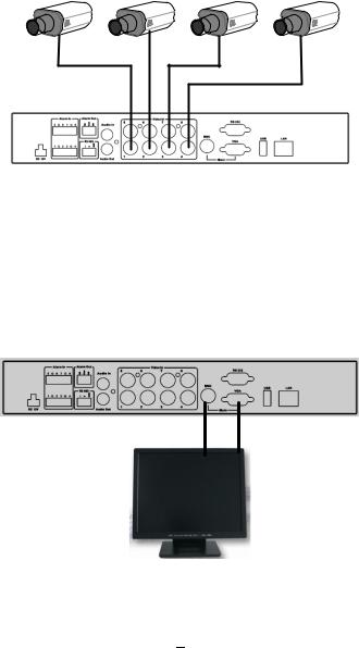
1.6.1 Video inputs
ATTENTION: In order for the system to auto-detect the appropriate video format (NTSC or PAL), make sure that there is a video signal on video input 1 upon power-up.
1.6.2 Monitor output
Depending on the used monitor, connection can be effected either through the VGA or the BNC socket. Supported resolutions for VGA: 1280 x 1024 / 60 Hz or 800 x 600 / 60 Hz, to be set in the MONITOR menu.
ATTENTION: BNC and VGA output can be used exclusively only. For switching between the two inputs, keep the VIEW key pressed for at least one second!
Monitor
8
1.7 ALARM CONTACT INSTALLATION
The alarm input can be used to start recording or for recording rate adjustment. In addition, alarm reactions such as camera display on the monitor, buzzer, e-mail and network alarm are available. The alarm output relay can be switched if required. Alarm input response actions can be controlled according to a flexible schedule.
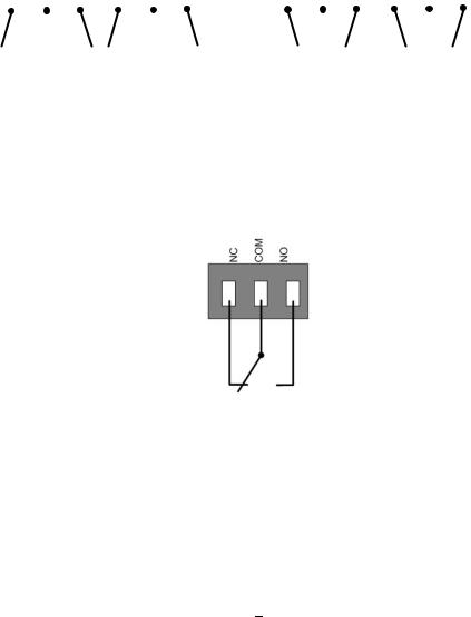
1.7.1Alarm Input Contacts
This DVR provides one alarm input per camera. The input is programmable N.O. (Normal Open) or N.C. (Normal Closed) Input has to be switched by dry contacts.
|
1 G 2 3 G 4 |
|
|
1 G 2 3 G 4 |
||||||||||||||||||||||||||||||||||||
|
|
|
|
|
|
|
|
|
|
|
|
|
|
|
|
|
|
|
|
|
|
|
|
|
|
|
|
|
|
|
|
|
|
|
|
|
|
|
|
|
|
|
|
|
|
|
|
|
|
|
|
|
|
|
|
|
|
|
|
|
|
|
|
|
|
|
|
|
|
|
|
|
|
|
|
|
|
|
|
|
|
|
|
|
|
|
|
|
|
|
|
|
|
|
|
|
|
|
|
|
|
|
|
|
|
|
|
|
|
|
|
|
|
|
|
|
|
|
|
|
|
|
|
|
|
|
|
|
|
|
|
|
|
|
|
|
|
|
|
|
|
|
|
|
|
|
|
|
|
|
|
|
|
|
|
|
|
|
|
|
|
|
|
|
|
|
|
|
|
|
|
|
|
|
|
|
|
|
|
|
|
|
|
|
|
|
|
|
|
|
|
|
|
|
|
|
|
|
|
|
|
|
|
|
|
|
|
|
|
|
|
|
|
|
|
|
|
|
|
|
|
|
|
|
|
|
|
|
|
|
|
|
|
|
|
|
|
|
|
|
|
|
|
|
|
|
|
|
|
|
|
|
|
|
|
|
|
|
|
|
|
|
|
|
|
|
|
|
|
|
|
|
|
|
|
|
|
|
|
|
|
|
|
|
|
|
|
|
|
|
|
|
|
|
|
|
|
|
|
|
|
|
|
|
|
|
|
|
|
|
|
|
|
|
|
|
|
|
|
|
|
|
|
|
|
|
|
Alarm input with N.O. (Normal Open) contact in idle state
Alarm input with N.C. (Normal Closed) contact in idle state
All settings are programmed in the ALARM menu (Section 4.5.1).
1.7.2Alarm Output Relay
The relay output provides either Normally Open or Normally Closed dry contacts.
Output relay in idle state
9
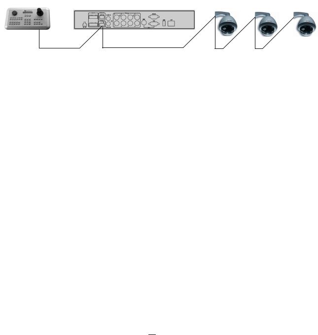
1.8 RS-485 KEYBOARD / PTZ INSTALLATION
All functions can be remote-controlled by the EKB-500 universal keyboard. Using the EEPbus protocol, digital video recorders, keyboards and speed domes can be installed on one single RS-485 bus. One system can comprise up to 8 keyboards.
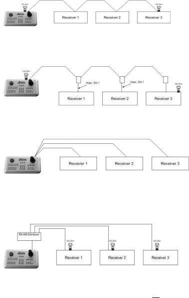
1.8.1General RS-485 bus installation
The EKB-500 keyboard uses a RS-485 simplex wiring; the signal is transferred via a single twisted pair line. CAT5 network cable is recommended, UTP version (unshielded) is sufficient for normal applications. A shielded cable should be used if the installed cables are expected to be highly susceptible to interference. The number of devices installed in one bus is limited to 32, and the maximum cable length is 3,900 feet. Both of these can be expanded using a signal distributor EverFocus Model EDA997A (see below).
Both the first and the last device in series should be terminated with 120 Ohm resistance in order to minimize line reflections.
RS-485 bus serial wiring
Cable length from box to device („Stubs“) has to be limited to 2m using connector boxes.
RS-485 bus serial wiring with connector boxes and connection cable
Direct RS-485 bus star wiring is not supported unless using an EverFocus Model EDA997A (see below).
Improper RS-485 bus star wiring
An EDA997A RS-485 signal distributor may be used to use a star wiring configuration.
Star wiring with RS-485 signal distributor
10
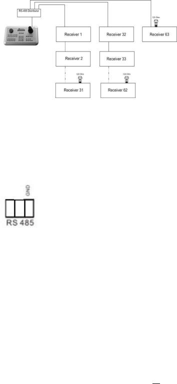
A RS-485 distributor can also be used to increase the maximum number of devices on the bus as well as the total range. Each distributor output provides another RS-485 bus. This allows each output to extend an additional 1200m, and it also enables the additional connection of 31 further devices to each output (the output itself represents one device).
The maximum system expandability depends on the RS-485 address range of the installed devices.
System expansion with RS-485 signal distributor
ATTENTION: EDA997A signal distributors are unidirectional! This means that the signal only flows from the input towards the outputs. Therefore, e.g. the interconnection of several keyboards is not possible with these types of signal distributor!
1.8.2RS-485 socket pin assignment
+ I
The RS485 pin assignment is as follows:
1.8.3EKB-500 connection with network patch cable
For a simple, short distance installation, recorder and keyboard can be connected directly using a standard CAT5 network cable with an 8-pin connector at only one end, and at the other end the Pin 3 wire connected to RS485 “+” (plus) and the pin 6 wire connected to RS-485 “-“ (minus).
1.8.4EKB-500 connection to several DVRs
For long distance installations connecting several DVRs, please use an EDA997A signal distributor to connect. For further details on keyboard connection, please refer to the EKB-500 manual.
RS-485 port communication settings are configured in the I/O CONTROL menu (Section 5.10.4 System Setup: I/O - control).
11
1.8.5Speed Dome Installation
Speed dome or telemetry receiver pan/tilt/zoom control is available through web browser or the optional PowerCon software if the DVR is connected to a network. Local telemetry control is provided by USB - mouse control or by the optional EKB-500 keyboard.
Supported protocols: EverFocus, Pelco-D, Pelco-P, Samsung, Transparent
Required DVR settings:
RS-485 receiver address in CAMERA menu (Section 4.3)
RS-485 parameters and protocol in the I/O CONTROL menu (Section 4.10.4)
ATTENTION: Some Pelco-D / -P protocol domes and receivers require an address offset of -1, i.e. the address assigned to the dome / receiver in the DVR camera menu must be 1 below the address set in the dome / receiver itself!
1.9 USB MOUSE INSTALLATION
Connect the USB mouse to one of the 2 USB ports. (This can be done while DVR is powered on) The rear USB V1.0 port is recommended to reserve the higher speed front USB V2.0 port for video copy/export.
NOTE: Recommended mouse types are Logitech® and Microsoft® wired USB wheel-mouse. Wireless USB mouse is not supported.
12
1.10 NETWORK CONNECTION
This section only describes physical connection to an Ethernet network. This step must be completed before the DVR can connect to the network. There are two basic types of connection:
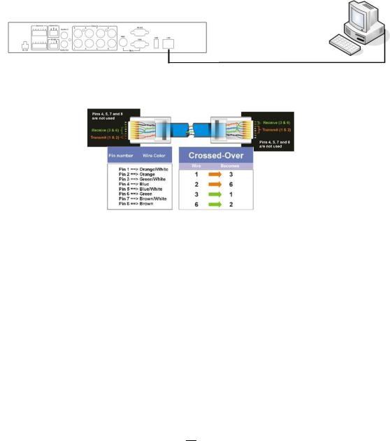
1.10.1 Direct PC Connection through Crossover Network Cable
The point-to-point connection of DVR and PC requires a crossover (crossed) network cable. This type of connection is ONLY used for direct connection to a single PC. Make sure that the PC is equipped with a 10/100 Mbps compatible network connection.
Figure 1-3 Direct PC Connection
Pinout of crossover-cable
1.10.2 Network Connection through Patch Cable
The connection to an existing network requires a normal patch cable (straight-through). The illustration shows the connection to a network switch or router.
13

Figure 1-4 Network Connection through Patch Cable
Pinout of straight patch cable
1.11 FINAL INSTALL PROCESS
Once you have completed the basic wiring connections, you are ready to turn on the DVR. Simply plug in the power source. The POWER LED will light up if power is normal. Once the system has finished loading, you can begin to set up the menu options for the DVR.
14
Chapter
2
2 MOUSE AND FRONT PANEL OPERATION
ECOR 264 F2/D2 DVRs support multiple sources to control the DVR. It can be controlled with a mouse, the front panel, an EKB 500 (optional), and the handheld IR remote control.
This chapter will cover the basic operation using the mouse and the front panel buttons.
2.1 GENERAL USB MOUSE OPERATION
2.1.1 |
How to select a channel |
|
1. |
In a view consisting of more than one channel, users can select a channel by clicking once on the |
|
|
desired channel screen. The selected screen will be highlighted by a white frame. |
|
2. |
Double clicking on a channel screen will display full screen for this channel. |
|
2.1.2 |
OSD Root Menu |
|
1. Right-click the mouse to obtain the DVR menu bar (see Figure 2-1 OSD Root Menu ). When you move the mouse over each icon, its title will be displayed at the top of the control bar.
Figure 2-1 OSD Root Menu
2.Click on any icon to perform that action. These actions are covered in detail in Chapter 3.
3.Click the “X” in the top-right corner to close the DVR control bar.
15
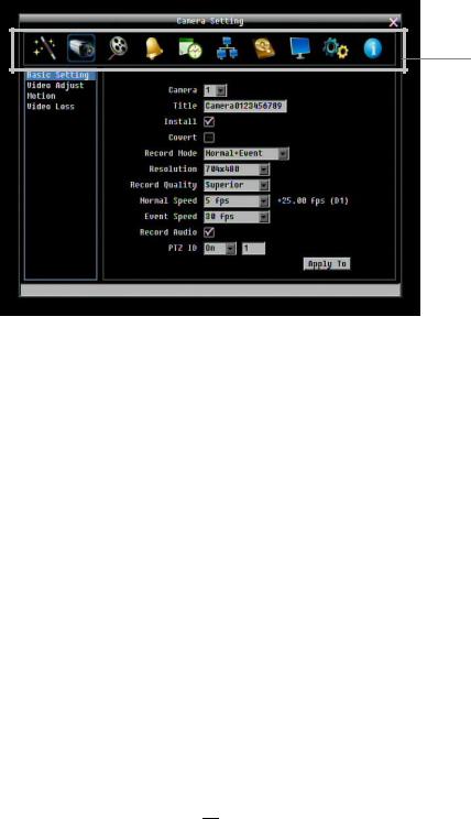
2.1.3Operation in the Configuration Menu
Click on the  icon to access the Configuration Menu.
The Configuration menu screens (shown in Figure 2-2 OSD Menu) are divided into 3 main sections.
1
2 |
|
|
|
|
|
|
3 |
|
|
|
|
|
|
||
|
|
|
|
|
|
|
|
Figure 2-2 OSD Menu
1.In section 1, there are ten setup options available. Move the mouse over an icon and click to select it.
2.In section 2, the choices for the selected icon will be displayed. Click on a choice to select it.
3.In section 3, all the options for the selected choice will be available. Click on a field to make changes.
2.1.4Field Input Options
The following are examples of different types of fields available in the Configuration menu.
 Textbox: Click on the box and an on-screen keyboard will appear*. (see note about the on-screen keyboard below)
 Dropdown box: Click on the down arrow to see all selections, then directly click on an option to select it.
 Check box: Click on the box to enable it (checked) or disable it (unchecked).
 Button: Click the button to execute the function.
16

 Bar: Click and hold on the bar to adjust the set point Left or Right.
* Note about on-screen keyboard:
Click on a button to input that character.
The buttons on the right and bottom have the following functions:
Space |
Enter a space |
|
|
Caps |
Switch to capital letters |
|
|
|
Delete the letter |
|
|
|
Confirm the selection |
|
|
|
Move to right |
|
|
|
Move to left |
|
|
17

2.2 GENERAL FRONT PANEL OPERATION
2.2.1 How to select a channel
1. In a view consisting of more than one channel, press the arrow keys (Up/Down/Right/Left) to scroll through each channel that is displayed. The selected channel will be highlighted by white frame. Pressing the “left” or “right” arrow when the last/first camera (1,4 or 8) is highlighted will select all cameras.
2.2.2 OSD Root Menu
1. Press “Menu” key to display the DVR menu bar. Use the left/right arrows to scroll over each icon. The title for each icon will be displayed on top of the menu bar.
2. Press “Enter” key on any icon to perform that action. These actions are covered in detail in Chapter 3 3. Press “Menu” to close the DVR menu bar.
2.2.3 Front Panel Key Review
The basic principle of front panel operation is to use arrow keys to navigate among the menu items. Use the “Enter” key to confirm a selection or enter the next level menu. Press the “Menu” key to enter the Main Menu or exit from the current level of the menu.
2.2.4Operation in Configuration Menu
Press “Menu”, use the arrow keys to highlight the “Configuration” icon, and press “Enter” with
“Configuration” icon highlighted to bring up the Configuration menu.
NOTE: If the require password option is active, you will need to log in first. Refer to “Section 3.2 LOGIN” for information on logging in.
The menu (shown in Figure 2-3 OSD Menu ) is divided into 3 main sections.
18

1
2 |
|
|
|
|
|
|
|
3 |
|
|
|
|
|||||
|
|
|
|
|
|
|
|
|
Figure 2-3 OSD Menu
1.In section 1, there are ten setup options available. Use arrow keys to highlight an icon and press “Enter” to select it.
2.In section 2, the main choices for the selected icon will be displayed. Use Up/Down arrow keys to highlight a choice and press “Enter” to select it.
3.In section 3, all the options for the selected choice will be available here. Use arrow keys to move between items and press “Enter” to make changes to that item.
Note: press the “Menu” button to go back to the previous menu section/level.
2.2.5Field Input Options
 Textbox: Press Enter key and an on-screen keyboard will appear*. (see note about on-screen keyboard below)
 Dropdown box: Press “Enter” key to show the available options. Use arrow keys to highlight the desired option and press “Enter” again to select it.
 Check box: Press “Enter” key on a setting to enable it (checked) or disable it (unchecked).
 Button: Press “Enter” key to execute the function.
 Bar: Press “Enter” key to activate the slider, then use arrow keys to adjust the setting. Press “Enter” again to finalize the changes.
19

* Note about on-screen keyboard:
Use the arrow buttons to highlight each character and press the “Enter” key on the front panel to input the selected characters. When finished, highlight “Done” and press the “Enter” key on the front panel to confirm. The buttons on the right and bottom have the following functions:
Space |
Enter a space |
|
|
Caps |
Switch to capital letters |
|
|
|
Delete the letter |
|
|
|
Confirm the selection |
|
|
|
Move to right |
|
|
|
Move to left |
|
|
20
Chapter
3
3 GENERAL DVR OPERATIONS
This chapter introduces the operations on major functions including playback, layout change, sequence, triplex operations, copy, and search.
3.1 RECORD
By default, the DVR will always be in record mode. When the DVR is turned on, it will start to record. The exceptions are:
1.DVR will not record any uninstalled cameras (Refer to Section 4.3.1 for more details)
2.If a schedule is active, the DVR will follow the record settings of the schedule.
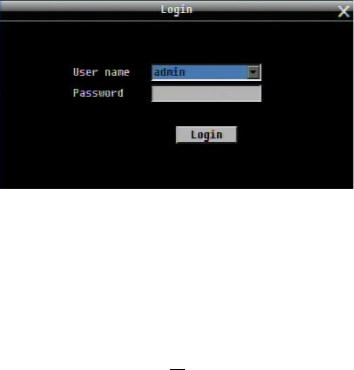
3.2LOGIN
In order to access ECOR 264 F2/D2 options, users may be asked to log in for authority identification. To log in, follow these steps.
1. Right click on the screen or press the Menu Key to display the Main Menu
Figure 3-1 Login page
2. Select the user name from the drop-down list and input the password. The defaults are: User name: admin (lower case)
Password: 11111111
21

(If you operate the device via front panel: Press the ENTER key to open the dropdown box. Use the up/down arrow keys to highlight the desired name and press the ENTER key to confirm your selection).
+To input password by mouse: click the password field to bring up the on-screen keyboard (see Figure 3-2 On-screen Keyboard). Click on each button to input the desired characters for the password. When finished, click “Done” on the on-screen keyboard to confirm the password.
+To input password using front panel: use the arrow keys to select the password field, then press the
“Enter” key to show the on-screen keyboard (see Figure 3-2 On-screen Keyboard). Use the arrow buttons to highlight each character and press the “Enter” key on the front panel to input the selected characters. When finished, highlight “Done” and press the “Enter” key on the front panel to confirm the password.
+ Click (or press “Enter” key when highlighted) on the “Login” button to log in to the system.
Figure 3-2 On-screen Keyboard
3.3 SELECT CAMERA OPERATION
ECOR 264 F2/D2 is a pentaplex DVR; users can control each camera individually by selecting that camera. For camera selection:
Mouse: Right-click the screen, the image will show a white frame on screen if the camera has been selected. When in quad display mode, press the quad layout icon in layout menu to select all four cameras.
Front panel: Use the arrows to change the selection. Pressing the “right” or “left” arrow when the last/first camera (1, 4 or 8) is highlighted will select all cameras.
3.4 PLAYBACK
The playback bar is the fastest way to show video from the exact time which users want to see. The playback bar allows a user to see both a time line and the current playback indicator. The user can then click the time line to move the indicator to the position which they want to see. The operation is as follows:
To playback:
By mouse: Right-click to bring up the menu bar and click on  to enter Playback Menu. By front panel: Press
  key to enter Playback Menu.
22

The playback bar will show (see figure below):
1 |
2 |
3 |
4 |
9 |
10 11 13 |
|
|
|
|
|
|
|
|
|
|
|
|
|
|
|
|
|
|
|
|
|
|
|
|
5 |
6 |
7 |
8 |
|
12 10 10 |
||||||
2009/05/25 09:09:30PM |
2009/05/25 09:09:40PM |
2009/05/25 09:10:30PM |
|||||||||
|
|
|
|
|
14 |
15 |
16 |
|
|
|
|
1.Stop key: press to stop playback
2.Slow Reverse key: press to start slow reverse playback
3.Pause key: press to pause playback
4.Slow Forward key: press to start slow forward playback
5.Fast Reverse key: press to start fast reverse playback
6.Reverse key: press to start reverse playback
7.Forward key: press to start forward playback
8.Fast Forward key: press to start fast forward playback
9.Time bar: Move the slider on the time bar to the select time to playback (The start time and end time for time bar appears below the bar). The status of each camera is represented by different colors on the time bar. Green means normal; orange indicates a Motion; blue indicates Video Loss, red indicates an alarm event.
10.“+” and “-“ signs are used to adjust the time scale range for the bar. Press “+” or “-“ to select between scale levels L1 ~ L5. When changing level, the start time and end time of the time bar will change
L1: Entire time bar is 2 days L2: Entire time bar is 30 hours. L3: Entire time bar is 1 hour.
L4: Entire time bar is 10 minutes. L5: Entire time bar is 1 minute.
11.Express copy: Press to start express copy when camera during playback (only one camera)
12.Playback speed indicator
13.Press “X” to close the playback bar.
14.Start time for bar (the left-most point of the time bar)
15.Current playback time (the time indicated by the slider)
16.End time for time bar (the right-most point of the time bar)
23

3.5 PTZ
3.5.1General PTZ control (if PTZ cameras are installed)
Right-click to bring up the menu bar and click on  to display PTZ Controls.
The following actions can be performed using the PTZ Menu:
1.Use Direction Arrows (up, down, left, right) to move the camera to the desired direction and angle.
2.To Zoom, Click “Z+” to zoom closer or “Z-” to zoom farther away.
3.To Focus, click “F+” to focus far or click “F-” to focus near.
4.With Iris, you can increase the amount of light by clicking “I+” or decrease it by clicking “I-
“.
5.To program a preset position (if supported by the camera)
a.Move PTZ camera to the specified position
b.Click “Preset” button
c.Click the number of the desired position (This will be displayed in the box)
d.Click “Set” button
6.To jump to a preset position
a.Click “Preset” button
b.Click the number of the desired position
c.Click “Go” button
7.Shortcut for presets #1-9
a.Click digit 1-9 button without clicking any other buttons
b.The camera will seek that preset position
8.Steps to delete a preset position (if supported by the camera)
a.Click “Preset” button
b.Click the number of the desired position
c.Click “Delete” button
9.For Auto Pan
a.Click “Auto Pan” button
10. Pattern Operation (Pattern is the “0” Tour in Everfocus and Pelco PTZ cameras)
a.Click “Pattern” button
11.Steps to run a tour
a.Click “Tour” button
b.Click the number of the desired tour
c.Click “Go” button
12.Steps to remove a tour (if supported by the camera)
a.Click “Tour” button
b.Click the number of the desired tour
c.Click “Delete” button
Click “C” to clear the digit in the number display
Click “X” at the top-right corner to hide the PTZ menu (see Express control below) Click “Exit” to leave PTZ function.
24
 Loading...