


Instruction Manual
pH 11 & pH 110
Hand-held pH / mV / Temperature / RS 232 Meter
Technology Made Easy ...
68X361301
Rev. 2 - 11/03
Preface
This manual serves to explain the use of the hand-held series meters. The models covered are the pH 11 and the pH 110 hand-held meters.
The manual functions in two ways, firstly as a step by step guide to help the user operate the meter. Secondly, it serves as a handy reference guide.
This instruction manual is written to cover as many anticipated applications of the pH meters as possible. If there are doubts in the use of the pH 11/110 meters, do not hesitate to contact the nearest Authorised Distributor.
It is recommended that all operators should read this manual prior to working with this instrument. Eutech Instruments / Oakton Instruments cannot accept any responsibility for damage or malfunction to the meter caused by improper use of the instrument.
The information presented in this manual is subject to change without notice as improvements are made, and does not represent a commitment on the part of Eutech
Instruments Pte Ltd / Oakton Instruments.
Copyright © 2003 All rights reserved.
Eutech Instruments Pte Ltd
Oakton Instruments
Rev. 2 - 11/03
TABLE OF CONTENTS
1 |
INTRODUCTION......................................................................................................................................... |
1 |
|
2 DISPLAY & KEYPAD FUNCTIONS......................................................................................................... |
2 |
||
|
2.1 |
DISPLAY................................................................................................................................................... |
2 |
|
2.2 |
KEYPAD ................................................................................................................................................... |
3 |
3 |
PREPARATION ........................................................................................................................................... |
5 |
|
|
3.1 |
INSERTING THE BATTERIES ...................................................................................................................... |
5 |
|
3.2 |
CONNECTING THE PH ELECTRODE TEMPERATURE PROBE & ELECTRODE HOLDER ................................. |
6 |
|
3.2.1 |
To connect pH, ORP or ISE electrode ............................................................................................ |
6 |
|
3.2.2 |
To connect the temperature probe: ................................................................................................. |
7 |
|
3.2.3 |
Attaching the Electrode Holder to the Meter .................................................................................. |
7 |
|
3.2.4 |
To attach a second electrode holder: .............................................................................................. |
7 |
|
3.2.5 |
Insert the electrode into the holder ................................................................................................. |
8 |
|
3.3 |
CONNECTING THE AC/DC ADAPTER ....................................................................................................... |
9 |
|
3.4 |
CONNECTING THE RS232C CABLE (ONLY FOR PH 110) .......................................................................... |
9 |
|
3.4.1 |
RS232C Configuration .................................................................................................................. |
10 |
4 |
CALIBRATION.......................................................................................................................................... |
11 |
|
|
4.1 |
IMPORTANT INFORMATION ON METER CALIBRATION ............................................................................ |
11 |
|
4.2 |
PREPARING THE METER FOR CALIBRATION ........................................................................................... |
11 |
|
4.2.1 |
pH 11 meter calibration ................................................................................................................ |
12 |
|
4.2.2 |
pH 110 meter calibration .............................................................................................................. |
12 |
|
4.3 |
PH CALIBRATION WITH ATC ................................................................................................................. |
13 |
|
4.4 |
MV CALIBRATION (OFFSET) (ONLY FOR PH 110)................................................................................... |
15 |
|
4.5 |
TEMPERATURE CALIBRATION ................................................................................................................ |
16 |
5 |
MEASUREMENT....................................................................................................................................... |
17 |
|
|
5.1 |
AUTOMATIC TEMPERATURE COMPENSATION ........................................................................................ |
17 |
|
5.2 |
MANUAL TEMPERATURE COMPENSATION ............................................................................................. |
18 |
|
5.3 |
TAKING MEASUREMENTS ...................................................................................................................... |
19 |
|
5.3.1 |
Taking measurements with READY indicator selected on ............................................................ |
19 |
|
5.3.2 |
Taking measurements with the AUTO HOLD feature selected on ................................................ |
19 |
6 |
HOLD FUNCTION..................................................................................................................................... |
20 |
|
7 |
MEMORY FUNCTION ............................................................................................................................. |
21 |
|
|
7.1 |
MEMORY INPUT ..................................................................................................................................... |
21 |
|
7.2 |
MEMORY RECALL.................................................................................................................................. |
22 |
8 PRINT FUNCTION (ONLY FOR PH 110) .............................................................................................. |
23 |
||
|
8.1 |
USING PH 110 METER WITH PRINTER OR COMPUTER............................................................................ |
23 |
|
8.2 |
SENDING DATA TO COMPUTER OR PRINTER .......................................................................................... |
23 |
|
8.2.1 |
Print Current Data Manually........................................................................................................ |
25 |
|
8.2.2 |
Print Data on Timed Interval ........................................................................................................ |
25 |
|
8.2.3 |
Print Data from Stored Memory ................................................................................................... |
26 |
9 |
ADVANCED SETUP FUNCTIONS.......................................................................................................... |
29 |
|
|
9.1 |
ADVANCED SETUP MODE OVERVIEW .................................................................................................. |
31 |
|
9.1.1 |
pH Setup mode .............................................................................................................................. |
31 |
|
9.1.2 |
mV Setup mode.............................................................................................................................. |
32 |
|
9.2 |
P1.0 : UNIT CONFIGURATION ................................................................................................................. |
33 |
|
9.2.1 |
P1.1: READY Indicator and Auto Hold function .......................................................................... |
34 |
|
9.2.2 |
P1.2: Select Calibration Buffer Options ....................................................................................... |
35 |
|
9.2.3 |
P1.3 Select Number of pH Calibration Points .............................................................................. |
36 |
|
9.2.4 |
P1.4 Select °C or °F Temperature Units....................................................................................... |
37 |
|
9.3 |
P2.0: VIEWING PREVIOUS CALIBRATION DATA ..................................................................................... |
38 |
|
|
9.4 |
P3.0: VIEW ELECTRODE DATA............................................................................................................... |
39 |
|
|
9.4.1 View pH Electrode Offset and Slope ............................................................................................. |
39 |
||
|
9.4.2 View mV Offset (Only for pH 110) ................................................................................................ |
40 |
||
|
9.5 |
P4.0 : AUTO-OFF.................................................................................................................................... |
41 |
|
|
9.6 |
P5.0 : RESET TO FACTORY DEFAULT ..................................................................................................... |
42 |
|
|
9.6.1 |
Calibration Reset .......................................................................................................................... |
42 |
|
|
9.6.2 |
User Reset ..................................................................................................................................... |
43 |
|
|
9.7 |
P 6.0: MEMORY CLEAR (CLR) .............................................................................................................. |
44 |
|
10 |
CYBERCOMM PORTABLE DAS (ONLY FOR PH 110) ................................................................. |
45 |
||
|
10.1 |
SYSTEM REQUIREMENTS........................................................................................................................ |
45 |
|
|
10.2 |
LOADING CYBERCOMM PORTABLE DAS............................................................................................... |
45 |
|
|
10.3 |
RUNNING CYBERCOMM PORTABLE ....................................................................................................... |
51 |
|
|
10.3.1 |
Buttons & Check-Box.................................................................................................................... |
52 |
|
|
10.3.2 |
Menu.............................................................................................................................................. |
53 |
|
|
10.3.3 |
Communication Settings................................................................................................................ |
54 |
|
|
10.4 |
CAPTURING AND PRINTING DATA INTO COMPUTER USING DATA ACQUISITION ................................... |
55 |
|
|
10.5 |
TROUBLE-SHOOTING GUIDE................................................................................................................... |
56 |
|
11 |
|
ELECTRODE CARE ............................................................................................................................. |
57 |
|
|
11.1 |
ELECTRODE MAINTENANCE................................................................................................................... |
57 |
|
|
11.1.1 |
Storage .......................................................................................................................................... |
57 |
|
|
11.1.2 |
After Use ....................................................................................................................................... |
57 |
|
|
11.1.3 Electrolyte Replacement (for refillable electrodes only)............................................................... |
57 |
||
|
11.2 |
ELECTRODE CLEANING .......................................................................................................................... |
58 |
|
|
11.3 |
ELECTRODE ACTIVATION....................................................................................................................... |
58 |
|
|
11.4 |
REJUVENATION PROCEDURE .................................................................................................................. |
59 |
|
12 |
|
ERROR MESSAGES.............................................................................................................................. |
60 |
|
13 |
|
TROUBLE-SHOOTING ........................................................................................................................ |
61 |
|
14 |
INFORMATION ON PH MEASUREMENT & ELECTRODE ........................................................ |
62 |
||
|
14.1 |
PH MEASUREMENTS .............................................................................................................................. |
62 |
|
|
14.1.1 |
Liquid Junction Potential .............................................................................................................. |
62 |
|
|
14.1.2 |
Asymmetry Potential ..................................................................................................................... |
62 |
|
|
14.1.3 |
pH and Temperature ..................................................................................................................... |
63 |
|
|
14.2 |
USE OF STANDARD PH BUFFERS ............................................................................................................ |
63 |
|
|
14.3 |
STANDARD PH BUFFERS ........................................................................................................................ |
64 |
|
15 |
|
LIST OF ACCESSORIES...................................................................................................................... |
65 |
|
|
15.1 |
REPLACEMENT METER AND METER ACCESSORIES................................................................................. |
65 |
|
|
15.2 |
OAKTON INSTRUMENTS ......................................................................................................................... |
66 |
|
|
15.3 |
CALIBRATION SOLUTIONS...................................................................................................................... |
67 |
|
16 |
|
FACTORY DEFAULT SETTINGS ...................................................................................................... |
68 |
|
|
16.1 |
PH 11 FACTORY DEFAULT SETTINGS ..................................................................................................... |
68 |
|
|
16.2 |
PH 110 FACTORY DEFAULT SETTINGS ................................................................................................... |
69 |
|
17 |
|
SPECIFICATIONS................................................................................................................................. |
70 |
|
18 |
|
WARRANTY........................................................................................................................................... |
71 |
|
19 |
|
RETURN OF ITEMS ............................................................................................................................. |
71 |
|

|
Instruction Manual |
CyberScan pH 11 / 110 |
|
|
|
|
|
|
|
|
|
|
|
|
|
|
|
|
|
1 INTRODUCTION
Thank you for selecting the pH 11/110 meter. These meters are microprocessorbased instruments and are designed to be handy, capable of allowing one-hand operation. Each has a large custom dual LCD for clear and easy reading. It is a unique and intelligent instrument that has the capability to cater to the preferences of the discerning individual. You have one of the two models:
•pH 11 meter
•pH 110 meter
Both meters have many user-friendly features – all of which are completely accessible through the splash-proof membrane keypad. Your meter includes a temperature probe, electrode holder, built-in meter stand and batteries. Eutech Instruments/ Oakton Instruments offer a wide selection of pH and ORP electrodes. Refer to Section 15 LIST OF ACCESSORIES on page 65 for more information.
The basic model is the pH 11 which is capable of measuring pH, Temperature, and millivolt (mV).
The deluxe model is the pH 110 which measures pH, Temperature, millivolt (mV) and relative millivolt (Rel mV). It has many advanced features and allows you to customise the meter settings. It also has a RS232C port that allows the meter to be connected to a computer or a printer via a cable for transferring data.
For power requirements, you can either use 4 AAA-sized batteries or an AC/DC power adapter (sold separately).
Please read this manual thoroughly before operating your meter.
1
|
Instruction Manual |
CyberScan pH 11 / 110 |
|
|
|
|
|
|
|
|
|
|
|
|
|
|
|
|
|
2 DISPLAY & KEYPAD FUNCTIONS
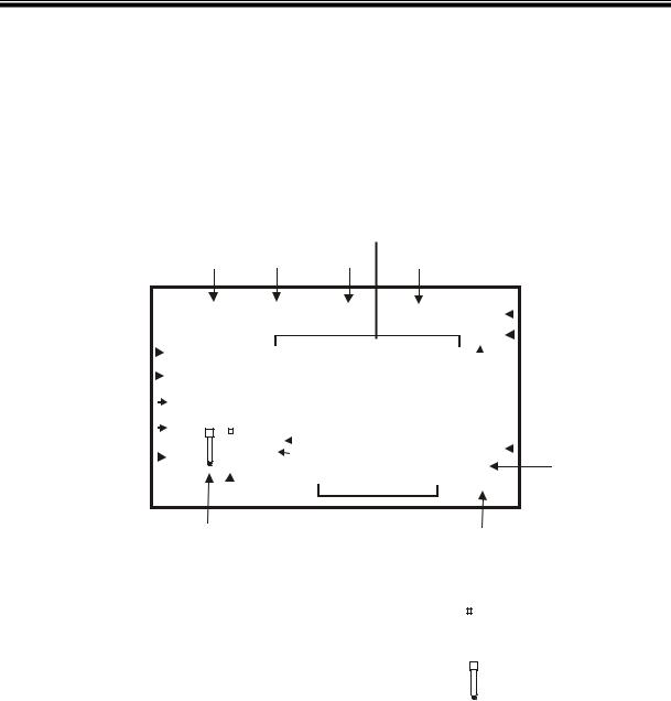
2.1Display
The LCD has a primary and secondary display.
•The primary display shows the measured pH or mV values.
•The secondary display shows the measured temperature.
The display also shows error messages, keypad functions and program functions.
Primary Display
1 |
2 |
3 |
4 |
|
|
|
|
|
|
|
SETUP MEAS CAL MEM |
R.mV |
|
|
|
5 |
|
|||||||||||||||||||
|
|
|
|
|
|
|
|
|
|
|
||||||||||||||||||||||
18 |
|
|
|
|
|
READY |
|
|
|
|
|
|
pH % |
|
|
6 |
|
|||||||||||||||
|
|
|
|
|
|
|
|
|
|
|
|
|
||||||||||||||||||||
|
|
|
|
|
|
|
|
|
|
|
|
|
|
|
|
|
|
|
|
|
|
|
||||||||||
16 |
|
|
|
|
|
ON |
-1.8.8.8 |
|
|
|
|
|
|
|
|
|
|
7 |
|
|||||||||||||
17 |
|
|
|
|
|
HOLD |
|
|
|
|
|
|
|
|
|
|
|
|
|
|
|
|
|
|
|
|
||||||
|
|
|
|
|
|
|
OFF |
|
|
MEM |
|
|
|
1.8.8.8 |
°C °F |
|
|
|
8 |
|
||||||||||||
|
|
|
|
|
|
|
|
|
|
|
|
|
|
|
|
|||||||||||||||||
|
|
|
|
|
|
|
|
|
|
|
|
|
|
|
|
|||||||||||||||||
|
|
|
|
|
|
|
|
|
|
|
|
|
|
|
|
|
|
|
|
|
||||||||||||
15 |
|
|
|
|
|
|
|
|
|
|
|
|
ERR |
|
|
|
|
|
|
|
||||||||||||
|
|
|
|
|
|
|
|
|
|
|
|
|
|
|
|
|
|
|
|
|
|
|||||||||||
|
|
|
|
|
|
|
|
|
|
|
|
|
|
- |
|
|
|
pHATC |
9 |
|
||||||||||||
|
|
|
|
|
|
|
|
|
|
|
|
|
|
|
|
|
|
|
|
|
|
|
|
|||||||||
|
|
|
|
|
|
|
|
|
|
|
|
|
|
|
|
|
|
|
|
|
|
|
|
|
|
|
|
|
|
|
|
|
|
|
|
|
|
|
|
14 13 |
12 |
11 |
|
|
10 |
|
|
|
|
|
|
|
|
||||||||||||
|
|
|
|
|
|
|
|
|
|
|
|
|
|
|
|
|
||||||||||||||||
|
|
|
|
|
|
|
|
|
|
|
|
|
|
|
|
|
|
Secondary Display |
|
|
|
|
|
|
|
|
|
|
|
|
||
|
|
|
|
|
|
|
|
|
|
|
|
|
|
Figure 1: Active LCD screen |
|
|
|
|
|
|
|
|
|
|
|
|
|
|||||
|
|
|
|
|
|
|
|
|
|
|
|
|
|
|
|
|
|
|
|
|
|
|||||||||||
|
1. SETUP - Setup mode |
|
|
|
|
|
|
7. pH - pH indicator |
|
|
|
|
|
|
|
|
|
|
|
|
|
|||||||||||
|
|
|
|
|
|
|
|
|
|
|
|
|
|
|
|
|
|
|
||||||||||||||
|
indicator |
|
|
|
|
|
|
|
|
|
|
|
|
|
13. |
|
|
- Low battery indicator |
|
|||||||||||||
|
|
|
|
|
|
|
|
|
|
|
|
|
|
|
|
|
|
|
|
|
|
|
||||||||||
|
|
|
|
|
|
|
|
|
|
|
|
|
|
|
|
|||||||||||||||||
|
2. MEAS - Measurement mode |
8. °C°F - Temperature |
|
|
|
|
|
|
|
|
|
|
|
|
|
|||||||||||||||||
|
|
|
|
|
|
|
|
|
|
|
|
|
||||||||||||||||||||
|
|
|
|
|
|
|
|
|
|
|
|
|
||||||||||||||||||||
|
indicator |
|
|
|
|
|
|
indicator |
|
|
|
|
|
14. |
|
|
|
- Electrode indicator |
|
|||||||||||||
|
|
|
|
|
|
|
|
|
|
|
|
|
|
|
|
|
|
|
|
|
|
|
|
|||||||||
|
|
|
|
|
|
|
|
|
|
|
|
|
|
|
|
|||||||||||||||||
|
3. CAL - Calibration indicator |
9. pH - pH buffer selection |
15. |
|
|
|
- Calibration buffer |
|
||||||||||||||||||||||||
|
|
|
|
|||||||||||||||||||||||||||||
|
|
|
|
|||||||||||||||||||||||||||||
|
|
|
|
|
|
|
|
|
|
|
|
|
indicator |
|
|
|
|
|
|
|
|
|
||||||||||
|
|
|
|
|
|
|
|
|
|
|
|
|
|
|
|
|
|
|
|
|
|
|||||||||||
|
|
|
|
|
|
|
|
|
|
|
|
|
|
|
|
|
|
indicator |
|
|
|
|
|
|
|
|||||||
|
|
|
|
|
|
|
|
|
|
|
|
|
|
|
|
|
|
|
|
|
|
|
|
|
|
|
||||||
|
|
|
|
|
||||||||||||||||||||||||||||
|
4. MEM - Memory recall mode |
10. ATC - Automatic |
16. ON – READY/Auto HOLD set |
|
||||||||||||||||||||||||||||
|
indicator |
|
|
|
|
|
|
Temperature Compensation |
|
|
|
|
up enable indicator. |
|
||||||||||||||||||
|
|
|
|
|
|
|
|
|
|
|
|
|
indicator |
|
|
|
|
|
OFF – READY set up disable |
|
||||||||||||
|
|
|
|
|
|
|
|
|
|
|
|
|
|
|
|
|
|
|
|
indicator |
|
|
|
|
|
|
|
|||||
|
5. R.mv - Relative millivolt (For |
11. MEM - Memory location |
17. HOLD – Hold indicator |
|
||||||||||||||||||||||||||||
|
pH 110 only)& millivolt |
|
|
|
|
|
|
indicator |
|
|
|
|
|
|
|
|
|
|
|
|
|
|
|
|
|
|
||||||
|
indicator (For both model) |
|
|
|
|
|
|
|
|
|
|
|
|
|
|
|
|
|
|
|
|
|||||||||||
|
6. % - Percentage indicator |
12 ERR - Error indicator |
18. READY – Ready indicator |
|
||||||||||||||||||||||||||||
|
|
|
|
|
|
|
|
|
|
|
|
|
|
|
|
|
|
|
|
|
|
|
|
|
|
|
|
|
|
|
|
|
|
|
|
|
|
|
|
|
|
|
|
|
|
|
|
|
|
|
|
|
|
|
|
|
|
|
|
|
|
|
|
|
|
2
Instruction Manual |
CyberScan pH 11 / 110 |
|
|
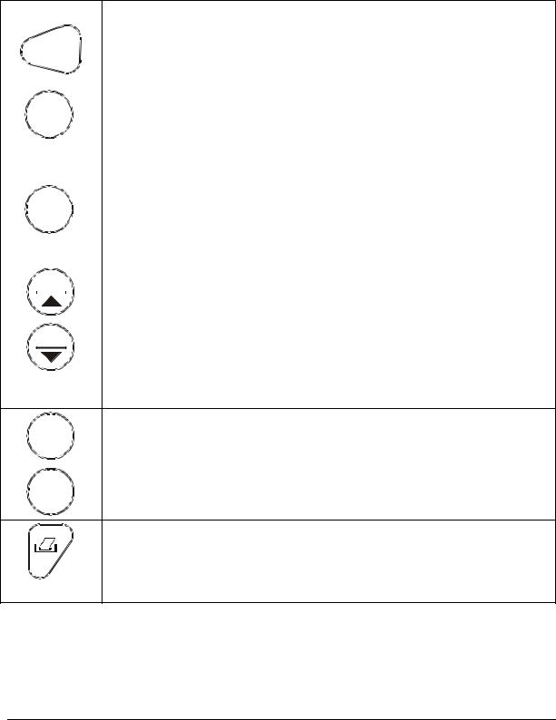
2.2Keypad
A large membrane keypad makes the instrument easy to use. Each button, when pressed, has a corresponding graphic indicator on the LCD (Figure 2 on previous page). Some buttons have several functions depending on its mode of operation.
|
|
|
KEY |
FUNCTION |
|||
|
|
|
|
ON |
• ON/OFF - Powers on and shuts off the meter. The meter will start in a |
||
|
|
|
|
measurement mode similar to the last measurement mode it is in before |
|||
|
|
|
|
OFF |
|||
|
|
|
|
being switched off. |
|||
|
|
|
|
|
|
|
|
|
|
|
|
|
|
|
• CAL - Activates the pH or Relative mV calibration mode and when used |
|
|
|
CAL |
with the MODE key, it activates the temperature calibration mode. |
|||
|
|
MEAS |
|
• MEAS - Allows return to measurement mode when canceling or terminating |
|||
|
|
|
|
|
|
|
any operation. |
|
|
|
|
|
|
|
|
|
|
|
|
|
|
|
• HOLD - Activates/Deactivates freezing of the measured reading while in |
|
|
|
|
|
|
|
measurement mode. |
|
|
HOLD |
• ENTER - Confirms the calibration values in Calibration mode and the |
||||
|
ENTER |
selection in SETUP and Print Function mode. |
|||||
|
|
|
|
|
|
|
Scroll through the memory location and the stored data during memory |
|
|
|
|
|
|
|
recall. |
|
|
|
|
MI |
• MI (Memory Input) - Captures the measured readings of the pH, Relative |
||
|
|
|
|
mV or mV with its corresponding temperature values and stores them in |
|||
|
|
|
|
|
|
|
|
|
|
|
|
|
|
|
the memory. |
• MR (Memory Recall) - Retrieves the stored data from memory.
MR |
• ▲▼ - Sets the calibration values during Relative mV or temperature |
|
|
|
calibration. |
Scrolls through each SETUP and its sub group menu.
Scroll through Print Function menu and its parameters.
|
• SETUP - Activates the parameter setting menu to allow you to customise |
SETUP |
meter configuration, view calibration points and electrode offset data, |
|
select auto power off, reset meter, and clear memory. |
|
|
|
• MODE - Selects the measurement parameter option between pH with |
MODE |
temperature, Relative mV with temperature (only pH 110), and mV with |
|
temperature. |
• PRINT - Allows print of current measurement or stored data to either the printer or the computer.
(pH 110)
3
Instruction Manual |
|
CyberScan pH 11 / 110 |
|
|
|
|
|
|
|
|
|
|
|
|
|
|
|
|
|
|
|
|
|
|
|
|
|
|
|
|
|
ON |
|
|
|
|
|
|
|
|
|
|
|
|
|
|
|
|
|
|
ON |
||||||||||||||||||||
|
|
|
|
|
|
|
|
|
|
|
|
|
|
|
|
|
|
|
|
|
|
|
OFF |
|
|
|
|
|
|
|
|
|
|
|
|
|
|
|
|
|
|
|
OFF |
|
||||||||||||||||||
|
|
|
|
|
|
|
|
|
|
|
|
|
|
|
|
|
|
|
|
|
|
|
|
|
|
|
|
|
|
|
|
|
|
|
|
|
|
|||||||||||||||||||||||||
|
|
|
|
|
|
|
CAL |
|
|
HOLD |
|
|
|
|
|
CAL |
|
|
HOLD |
|||||||||||||||||||||||||||||||||||||||||||
|
|
|
|
|
|
|
|
|
|
|
|
|
|
|||||||||||||||||||||||||||||||||||||||||||||||||
|
|
|
|
|
|
|
||||||||||||||||||||||||||||||||||||||||||||||||||||||||
|
|
|
|
|
MEAS |
|
|
|
|
|
|
|
ENTER |
|
|
MEAS |
|
|
|
|
|
|
|
ENTER |
||||||||||||||||||||||||||||||||||||||
|
|
|
|
|
|
|
|
|
|
|||||||||||||||||||||||||||||||||||||||||||||||||||||
|
|
|
|
|
|
|
|
|
|
|
|
|
|
|
|
|
|
|
|
|
|
|
|
|
|
|
|
|
|
|
|
|
|
|
|
|
|
|
|
|
|
|
|
|
|
|
|
|
|
|
|
|
|
|
|
|
|
|||||
|
|
|
|
|
|
|
|
|
|
|
|
|
|
|
|
|
|
|
|
|
|
|
|
|
|
|
|
|
|
|
|
|
|
|
|
|
|
|
|
|
|
|
|
|
|
|
|
|
|
|
|
|
|
|
|
|
||||||
|
|
|
|
|
|
|
|
|
MI |
|
|
|
|
MR |
|
|
|
|
MI |
|
|
|
|
MR |
|
|||||||||||||||||||||||||||||||||||||
|
|
|
|
|
|
|
|
|
|
|
|
|
|
|
|
|
|
|
|
|
|
|
|
|
|
|
|
|
|
|
|
|
|
|
|
|
|
|
|
|
|
|
|
|
|
|
|
|
|
|
|
|
|
|||||||||
|
|
|
|
|
|
|
|
SETUP |
|
|
|
|
MODE |
|
|
SETUP |
|
|
MODE |
|||||||||||||||||||||||||||||||||||||||||||
|
|
|
|
|
|
|
|
|
|
|||||||||||||||||||||||||||||||||||||||||||||||||||||
|
|
|
|
|
|
|
|
|
|
|
|
|
|
|
|
|
|
|
|
|
|
|
|
|
|
|
|
|
|
|
|
|
|
|
|
|
|
|
|
|
|
|
|
|
|
|
|
|
|
|
|
|
|
|
|
|
|
|
|
|
|
|
|
|
|
|
|
|
|
|
|
|
|
|
|
|
|
|
|
|
|
|
|
|
|
|
|
|
|
|
|
|
|
|
|
|
|
|
|
|
|
|
|
|
|
|
|
|
|
|
|
|
|
|
|
|
|
|
|
|
|
|
|
|
|
|
|
|
|
|
|
|
|
|
|
|
|
|
|
|
|
|
|
|
|
|
|
|
|
|
|
|
|
|
|
|
|
|
|
|
|
|
|
|
|
|
|
|
|
|
|
|
|
|
|
|
|
|
|
|
|
|
|
|
|
|
|
|
|
|
|
|
|
|
|
|
|
|
|
|
|
|
|
|
|
|
|
|
|
|
|
|
|
|
|
|
|
|
|
|
|
|
|
|
|
|
|
|
|
|
|
|
|
|
|
|
|
|
|
|
|
|
|
|
|
|
|
|
|
|
|
|
|
|
|
|
|
|
|
|
|
|
|
|
|
|
|
|
|
|
|
|
|
|
|
|
|
|
|
|
|
|
|
|
|
|
|
|
|
|
|
|
|
|
|
|
|
|
|
|
|
|
|
|
|
|
|
|
|
|
|
|
|
|
|
|
|
|
|
|
|
|
|
|
|
|
|
|
|
|
|
|
|
|
|
|
|
|
|
|
|
|
|
|
|
|
|
|
|
|
|
|
|
|
|
|
|
|
|
|
|
|
|
|
|
|
|
|
|
|
|
|
|
|
|
|
|
|
|
|
|
|
|
|
|
|
|
|
|
|
|
|
|
|
|
|
|
|
|
|
|
|
|
|
|
|
|
|
|
|
|
|
|
|
|
|
|
|
|
|
|
|
|
|
|
|
|
|
|
|
|
|
|
|
|
|
|
|
|
|
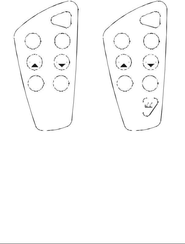
Keypad for pH 11 meter |
Keypad for pH 110 meter |
Figure 2: pH 11 and pH 110 keypads
4

|
Instruction Manual |
CyberScan pH 11 / 110 |
|
|
|
|
|
|
|
|
|
|
|
|
|
|
|
|
|
3 PREPARATION
3.1Inserting the Batteries
This meter is packaged with 4 “AAA” alkaline batteries required for operation. To insert the batteries into the meter, follow the procedure outlined below.
1.To open the battery compartment, press down the catch of the battery cover. See below.
2.Note the polarity and insert the batteries into the battery compartment correctly
3.Replace the battery cover into its original position, ensuring the catch is locked in position.
Your hand-held meter is now ready for operation.
LR03 'AAA' (AM4)
MADE IN S'PORE
Figure 4: Note battery's polarity
Figure 3: Open Battery Cover
5
Instruction Manual |
CyberScan pH 11 / 110 |
|
|
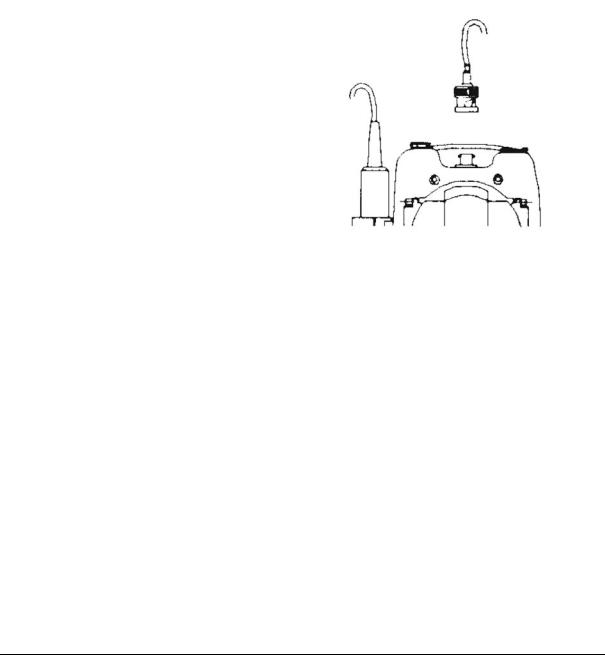
3.2 Connecting the pH Electrode Temperature Probe & Electrode
Holder
The pH 11/110 meter uses any standard pH, ORP, or Ion Selective Electrode (ISE) with a BNC connector. For Automatic Temperature Compensation (ATC), this meter requires a temperature probe with a phono-jack connector.
NOTE: It is important that water does not get into the BNC connector. Also avoid touching the connector with soiled hands.
3.2.1 To connect pH, ORP or ISE electrode
1.Insert the BNC connector from the electrode over the BNC connector socket on the meter.
2.Make sure the slots of the connector are in line with the posts of the socket.
3.Slide the BNC connector of the electrode over (Figure 5).
4.Rotate the connector clockwise until it locks.
5.To remove electrode, push and rotate the connector counterclockwise.
Figure 5: Insert the BNC connector from the electrode cable into the BNC socket on the meter.
6.While holding onto the metal part of the connector, pull it away from the meter.
7.Be careful not to use excessive force.
CAUTION: Do not pull on the probe cord or the probe wires might disconnect.
Refer to section 15 LIST OF ACCESSORIES section on page 65 for information on temperature probe and other electrodes.
6
Instruction Manual |
CyberScan pH 11 / 110 |
3.2.2 To connect the temperature probe:
The temperature probe (provided) uses a 2.5 mm phono jack to connect with the socket on the pH 11/110. Insert the jack fully into the socket (Figure
6).
Note: Calibrate your temperature probe when you replace the probe and when using a “3-in-One” combination pH and temperature probe. See section 4.5 - Temperature Calibration on page 16 for instructions.
Figure 6: Insert temperature probe
3.2.3Attaching the Electrode Holder to the Meter
The pH meter is designed to allow you to do a one hand operation for any measurement or calibration. For that purpose, two electrode holders are provided. They are designed for easy use and installation. Care must be taken to avoid use of excessive force in the process of attaching these components.
1.Locate the slot on the right-hand side of the meter.
2.Gently slide the flange of the holder into the slot on the meter. Make sure the holder is secured properly into the slot (Figure 7).
3.You can attach the electrode holder in different positions (Figure 9).
Figure 7: Insert electrode holder
3.2.4 To attach a second electrode holder:
The electrode holder is designed such that you can attach one holder onto another.
Up to two electrodes (using the BNC connector and phono-jack) can be used with the meter at any one time.
7

Instruction Manual |
CyberScan pH 11 / 110 |
1.Align the flange of the second electrode holder with the slot of the first holder
(Figure 8).
2.Slide the flange of the second holder into the slot of the first holder until the tops of the holders are aligned and secure.
Figure 8: To attach a second electrode holder
3.2.5Insert the electrode into the holder
1.Do not use excessive force when inserting electrodes into the holders.
2.Insert the pH electrode into the opening of the first holder until the top housing of the electrode touches the top of the holder.
3. If you are using a separate temperature probe, insert the probe into the opening of the second holder until the ridge on the housing touches the top of the holder.
Figure 9: Different positions for one hand operation
NOTE: The holder is designed for
probes 12 mm in diameter. Electrodes larger than 12 mm may not fit in the holder.
Forcing the electrode into the opening may damage the holder or your electrode.
The electrode holders can be attached in different positions for greater flexibility in measurement and storage purposes. Simply slide out the electrode holders and reorient into appropriate orientation before putting into position.
8
Instruction Manual |
CyberScan pH 11 / 110 |
3.3Connecting the AC/DC Adapter
Besides using four AAA-sized batteries as a power source, the pH 11/110 meter can also operate from the power mains using an AC/DC power adapter either at 120/220 VAC (sold separately). This is extremely useful if you have an A.C. power source available (e.g. laboratory).
Before plugging in, switch off the meter and the power source of adapter. This is a safety precaution that should be adhered to safeguard your meter.
1.Switch off the meter and power sources.
2.Select the correct AC/DC Adapter either at 120/220 VAC which matches your input mains voltage.
3.Select the correct output voltage of the AC/DC adapter. (Output Voltage: 9 to 15 V DC, Current: >=50 mA).
4.Gently insert the power adapter D.C. jack into the meter power socket.
5.Switch on the power source of the adapter followed by the meter.
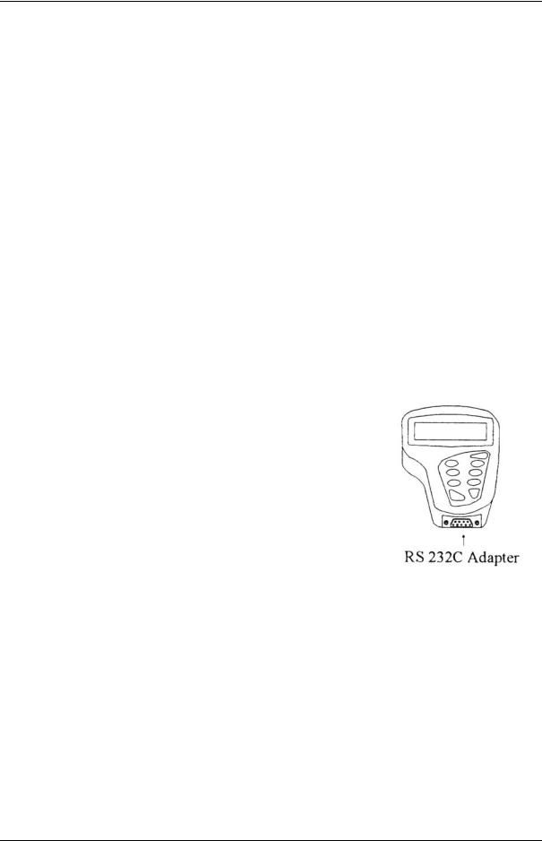
3.4Connecting the RS232C Cable (Only for pH 110)
The pH 110 meter provides a RS232C output for you to transmit your readings either to a printer or a computer via a cable. This is useful in instances where the meter is used for continuous monitoring of a certain process or experiment. Data output to the printer or the computer can then be evaluated.
The data is output in the ASCII format. This format allows the data to be imported by a wide variety of software that read ASCII data (e.g. Microsoft’s Excel, Lotus, Quattro-pro etc.). A complimentary Data Acquisition Software (DAS) is provided and it captures data transmitted into an ASCII file for later use.
Figure 10: Location of
RS232C
1.Open the printer port cover located at the bottom
end of the meter. Do not use excessive force when doing this. See Figure 10.
2.Noting the orientation of the RS232C connector, plug the male connector into the RS232C port of the meter.
3.Fasten the RS232C connector by fastening the two screws at the side of the male RS232C connector.
9

Instruction Manual |
CyberScan pH 11 / 110 |
3.4.1 RS232C Configuration
The pH 110 meter has a 9 pin female RS232C connector with the following pin out:
PIN NO. |
DESCRIPTION |
1 |
- |
2 |
Transmit Data |
3 |
- |
4 |
- |
5 |
CTS (Clear to Send) |
6 |
- |
7 |
GND (Ground) |
8 |
- |
9 |
- |
A one-to-one connection can be made with a 9 pin RS232C port of the computer.
5 |
4 |
3 |
2 |
1 |
9 |
8 |
7 |
6 |
In case pH 110 meter’s output has to be sent to a 25 pin RS232C connector, the following cable configuration may be used:
pH 110 |
25 pin connector |
2 (TxD) |
(RxD) 3 |
5 (CTS) |
(RTS) 4 |
7 (GND) |
(GND) 7 |
10

|
Instruction Manual |
CyberScan pH 11 / 110 |
|
|
|
|
|
|
|
|
|
|
|
|
|
|
|
|
|
4 CALIBRATION
4.1Important Information on Meter Calibration
When you re-calibrate your meter, previous pH and Relative mV calibration points are replaced on a point by point basis. For example, if you previously calibrated your meter at pH 4.01, 7.00, and 10.01, and you have now re-calibrated at pH 7.00, the meter retains the old calibration data at pH 4.01 and pH 10.01. To view current calibration points, see section 9.3 - P2.0: Viewing Previous Calibration Data on page 38.
To completely re-calibrate your meter, or when you use a replacement probe, it is best to set the meter to its factory defaults and re-calibrate the meter at all points. To reset the meter to its factory defaults, see section 9.6.2 - User Reset on page 43.
4.2Preparing the Meter for Calibration
Before starting calibration, make sure you are in the correct measurement mode.
When you switch on the meter, the meter starts up in the units last used. For example, if you shut the meter off in “mV” units, the meter will read “mV” units when you switch the meter on.
Be sure to remove the protective electrode storage bottle or rubber cap of the electrode before calibration or measurement. If the electrode has been stored dry, wet the electrode in tap water for 10 minutes before calibrating or taking readings to saturate the pH electrode surface and minimise drift.
Wash your electrode in deionised water after use, and store in electrode storage solution. If storage solution is not available, use pH 4.01 or 7.00 buffer solution.
Do not reuse buffer solutions after calibration. Contaminants in the solution can affect the calibration, and eventually the accuracy of the measurements. See section 15.3 -
Calibration Solutions on page 67 for information on our high-quality pH buffer solutions.
It is recommended that you perform at least a 2-Point Calibration using standard buffers that adequately cover the expected measurement range prior to measurement. 1-Point Calibration can also be used for quick measurements. Make sure that the calibration point is close to the sample value to be measured.
11

Instruction Manual |
CyberScan pH 11 / 110 |
|
|
4.2.1 pH 11 meter calibration
The pH 11 meter is capable of up to 5-point pH calibration to ensure accuracy across the entire pH range of the meter. You can select from the following buffer options:
•USA buffers --- pH 1.68, 4.01, 7.00, 10.01, and 12.45.
•NIST buffers --- pH 1.68, 4.01, 6.86, 9.18, and 12.45.
4.2.2 pH 110 meter calibration
The pH 110 meter features four separate internationally recognised buffer standards.
Select the buffer standard you require in section 9.2.2 - P1.2: Select Calibration Buffer Options on page 35.
This meter is capable of up to 6-point pH calibration, depending on the buffer standard selection. You can select from the following buffer options:
•USA buffers --- pH 1.68, 4.01, 7.00, 10.01, and 12.45.
•NIST buffers --- pH 1.68, 4.01, 6.86, 9.18, and 12.45.
•DIN buffers --- pH 1.09, 3.06, 4.65, 6.79, 9.23, and 12.75.
•PWB (Low Ionic): pH 4.10 and 6.97
The meter automatically recognises and calibrates to these standard buffer values, which makes pH calibration faster and easier.
12
Instruction Manual |
CyberScan pH 11 / 110 |
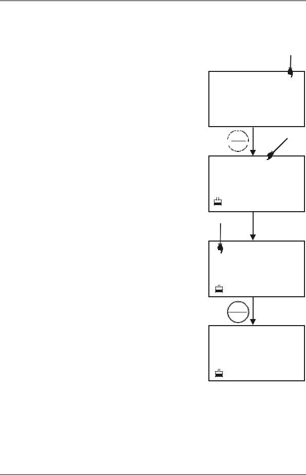
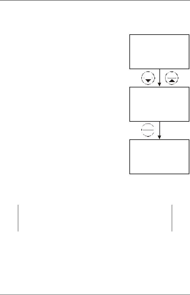
4.3pH Calibration with ATC
NOTE: We recommend that you perform at least 2-point calibration using standard buffers that bracket (one above and one below) the expected sample range.
1.If necessary, press the MODE key to select pH mode. The pH indicator appears in the upper right hand corner of the display.
2.Rinse the probe thoroughly with de-ionised water or a rinse solution. Do not wipe the probe; this causes a build-up of electrostatic charge on the glass surface.
3.Dip the probe into the calibration buffer. The end of the probe must be completely immersed into the sample. Stir the probe gently to create a homogeneous sample.
4.Press CAL/MEAS key to enter pH calibration mode. The CAL indicator will be shown. The primary display will show the measured reading while the smaller secondary display will indicate the pH standard buffer solution.
5.Wait for the measured pH value to stabilise
(The READY indicator will be shown only if it is activated in the set up menu).
6.Press HOLD/ENTER key to confirm calibration. The meter is now calibrated to the current buffer.
See figure on right.
MEAS
7.16 pH
°C
22.3 ATC
CAL
 MEAS
MEAS 
CAL
pH
7.16
7.00 pH
|
CAL |
READY |
7.16 pH |
|
7.00 pH |
|
HOLD |
|
ENTER |
|
CAL |
READY |
7.00pH |
7.00 pH
Figure 11: pH Calibration
sequence
13

Instruction Manual |
CyberScan pH 11 / 110 |
|
|
7.Rinse the probe with de-ionised water or a rinse solution, and place it in the next pH buffer.
8.Follow steps 5 and 6 for additional calibration points. See Figure 12.
9.When all the calibration points set in the Unit Configuration Setup (see P1.3 Select Number of pH Calibration Points on page 36) are completed, the meter returns to Measurement mode automatically. However, if you wish to terminate the calibration without completing the number of points as set in the Unit Configuration Setup menu, press CAL/MEAS to return to pH measurement mode.
CAL
READY 4.15 pH
4.01 pH
 HOLD
HOLD 
 ENTER
ENTER
CAL
READY 4.01 pH
4.01 pH
Figure 12: Proceed to next calibration point
NOTES:
1.To exit from pH calibration mode without confirming calibration, DO NOT press ENTER in step 6. Press
CAL/MEAS instead.
2.To limit the number of pH buffer values available during calibration, see P1.3 Select Number of pH Calibration Points on page 36.
14
Instruction Manual |
CyberScan pH 11 / 110 |
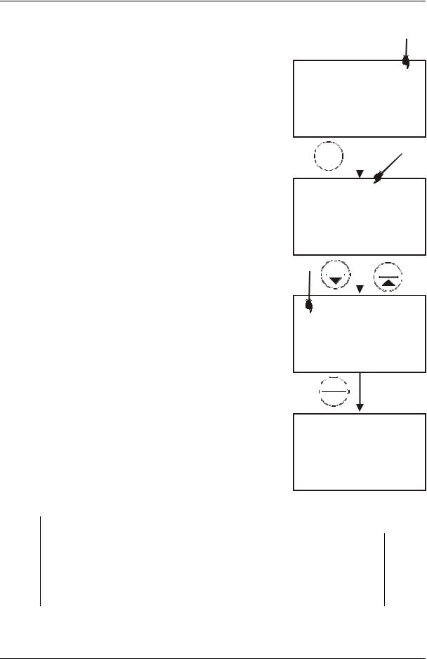
4.4mV Calibration (Offset) (Only for pH 110)
With pH 110 meter, you can perform a calibration or an offset of up to ±150 mV. Note: For Oxidation reduction Potential (ORP) or Redox measurements, an ORP electrode must be used.
1.While in the measurement function, press MODE to enter the mV mode. The mV indicator appears in the upper right hand corner. See figure at right.
2.Press the CAL/MEAS key. The CAL indicator appears above the primary display. The primary display shows the relative mV reading and the secondary display shows the absolute mV value.
•If you have never calibrated relative mV or if the meter has been reset, the value shown in the primary display is the same as the absolute mV value.
•“R.” annunciator will appear once mV calibration is performed, an indication of mV offset.
3.Press the MI/▲ or MR/▼keys to enter the relative mV value that matches your desired reading.
4.Press the HOLD/ENTER key to confirm the reading and to return to the measurement mode.
The primary display now shows the relative mV reading.
NOTES:
MEAS
133.4 |
mV |
||||||
|
|||||||
|
|
|
|
24.5 |
°C |
||
|
|
|
|
ATC |
|||
|
CAL |
|
|
|
|||
|
|
|
|
||||
|
MEAS |
|
|
|
|
||
|
|
|
|
|
|
|
|
|
|
|
|
CAL |
mV |
||
133.4 |
|||||||
|
|||||||
|
|
|
|
133.4 |
|
||
|
|
MR |
|
MI |
|
||
|
|
|
|
||||
|
|
|
|
|
CAL |
|
|
|
|
|
|
|
|
||
READY |
|
|
mV |
||||
155.0
133.4
 HOLD
HOLD 
 ENTER
ENTER
MEAS
R.mV
READY
155.0
°C
24.5 ATC
Figure 13: mV calibration sequence
1.To view the mV offset value, see section 9.4.2 - View mV Offset on page 40.
2.To reset all calibration and offset values in memory to the factory default settings, see section 9.6.1 - Calibration Reset page 42.
15
Instruction Manual |
CyberScan pH 11 / 110 |
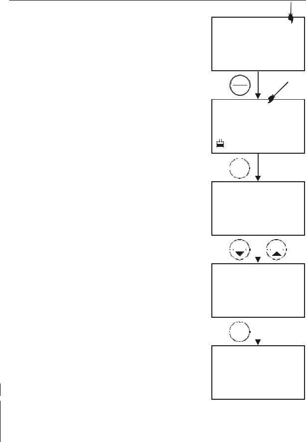
4.5Temperature Calibration
The temperature sensor is factory calibrated. Calibrate the temperature probe only if you suspect temperature errors may have occurred over a long period of time or if you have a replacement temperature probe. This procedure offers offset adjustment of probe to ensure more accurate temperature measurement.
1.Make sure the ATC probe (or temperature connector of the electrode) is connected to the phono-socket (see Figure 6).
2.Switch the meter on. The ATC annunciator will appear at the right-hand side of the LCD. Press the MODE key to select pH mode.
3.Press the CAL/MEAS key to enter pH calibration mode. The CAL indicator will appear above the primary display.
MEAS
7.16 pH
°C
22.3 ATC
CAL
MEAS
CAL
pH
7.16
7.00 pH

 MODE
MODE
CAL
4. While in pH calibration mode, press the MODE |
22.3 |
key to enter temperature calibration mode. The |
|
primary display shows the measured |
|
temperature reading according to the last set |
|
|
|
|
|
22.3 |
°C |
|||
|
|
|
|
|
ATC |
|||||
offset1 and the secondary display shows the |
|
|
|
|
|
|
|
|
|
|
|
|
|
|
|
|
|
|
|
|
|
factory calibrated temperature measurement. |
|
|
MR |
|
|
MI |
|
|||
5. Dip the ATC probe (or electrode) into a solution |
|
|
|
|
|
|
|
|
|
|
|
|
|
|
|
|
|
|
|
|
|
of known temperature (i.e. a temperature bath). |
|
|
|
|
|
|
CAL |
|
||
Allow time for the temperature probe to |
|
|
|
|
|
22.0 |
||||
stabilise. |
|
|
|
|
|
|||||
6. Scroll with the MI/▲ or MR/▼ keys to set the |
|
|
|
|
|
|||||
|
|
|
|
|
|
|
|
|
°C |
|
|
|
|
|
|
|
22.3 ATC |
||||
correct temperature value (i.e. the temperature |
|
|
|
|
|
|
||||
of the temperature bath). You can adjust the |
|
|
|
|
|
|
|
|
|
|
reading in increments of 0.1°C. |
|
|
HOLD |
|
|
|
|
|
|
|
|
ENTER |
|
|
|
|
|
||||
|
|
|
|
|
|
|
||||
7. Once you have selected the correct |
|
|
MEAS |
|
|
|
|
|
||
temperature, press the HOLD/ENTER key. The |
|
|
|
|
|
|
pH |
|||
|
7.16 |
|||||||||
READY |
|
|||||||||
meter automatically returns to pH measurement |
|
|||||||||
|
|
|||||||||
mode. See Figure 14. |
|
|
||||||||
|
|
|
|
|
22.0 |
|
°C |
|||
|
|
|
|
|
|
|
||||
NOTES: |
|
|
|
|
|
|
ATC |
|||
You can offset the temperature reading up to ±5°C from |
Figure 14: Temperature |
|||
original reading. |
||||
calibration |
||||
To exit this program without confirming the temperature |
||||
|
|
|||
calibration value, DO NOT press ENTER. Press CAL/MEAS instead. |
|
|||
|
|
|
|
|
1 It displays the value being measured currently, offset by the last calibration. |
|
|
||
16 |
|
|
||
Instruction Manual |
CyberScan pH 11 / 110 |
5 MEASUREMENT
This meter is capable of taking measurements with automatic or manual temperature compensation. Automatic temperature compensation only occurs when a temperature sensor is plugged into the meter. If there is no temperature sensor plugged into the meter, the default manual temperature setting is automatically 25.0
°C. You can manually set the temperature to match your working conditions using a separate thermometer.
NOTE: Remove the protective rubber cap or soaker bottle of the electrode before proceeding with measurement. Take care not to exert too much force as this may cause damage to the electrode.
5.1Automatic Temperature Compensation
For automatic temperature compensation (ATC) simply plug the temperature probe into the meter. The ATC indicator will light up on the LCD.
NOTE: If you are using a temperature probe, the probe must be submersed in the liquid you are measuring.
MEAS
pH
7.05
°C
24.5 ATC
Figure 15: ATC indicator
17
Instruction Manual |
CyberScan pH 11 / 110 |
5.2Manual Temperature Compensation
IMPORTANT: For manual compensation, you must disconnect probe. The [ATC] annunciator will disappear from the LCD.
1.Switch the meter on. Press the MODE key to select pH mode.
2.Press the CAL/MEAS key to enter pH calibration mode. The CAL indicator will appear above the primary display.
3. While in pH calibration mode, press the MODE |
MR |
key to enter temperature calibration mode. The |
|
primary display act as the adjustable |
|
temperature setting and the secondary display |
|
shows the default temperature value of 25°C or |
|
indicates the last set temperature setting. |
|
4.Check the temperature of your sample using an accurate thermometer.
the temperature
CAL
25.0
25.0 °C
MI
CAL
30.0
25.0 °C
5.Press the MI/▲ or MR/▼ keys to set the temperature to the measured value from step 4.
6.Press HOLD/ENTER key to confirm the selected temperature and to return to the pH measurement mode.
7.The meter will now compensate pH readings for the manually set temperature.
See Figure on right.
 HOLD
HOLD
 ENTER
ENTER
MEAS
READY 7.05pH
 30.0 °C
Figure 16: Manual temperature compensation
NOTES:
To exit this program without confirming the manual temperature compensation value, DO NOT press ENTER in step 6. Press CAL/MEAS instead.
18

Instruction Manual |
CyberScan pH 11 / 110 |
5.3Taking Measurements
Be sure to remove the electrode soaker bottle or protective rubber cap on the electrode before measurement.
To take readings:
1.Rinse the probe with de-ionised or distilled water before use to remove any impurities adhering to the probe body. If the pH electrode has dehydrated, soak it for 30 minutes in electrode storage solution or 2M – 4M KCl solution (sold separately).
MEAS
pH
8.23
°C
21.3 ATC
2.Press ON to switch on meter. The MEAS
annunciator appears on the top center of the
LCD. The ATC indicator appears in the lower
right-hand corner to indicator Automatic Temperature Compensation (section
5.2 on Manual Temperature Compensation).
3.Dip the probe into the sample.
When dipping the probe into the sample, the sensor or the glass bulb of the electrode must be completely immersed into the sample. Stir the probe gently in the sample to create a homogeneous sample.
4.Allow time for the reading to stabilise. Note the reading on the display.
5.To toggle between pH and mV (or Rel mV) readings, press the MODE key.
5.3.1Taking measurements with READY indicator selected on
If the READY indicator has been activated, the READY annunciator lights when the reading is stable2 *. You can switch the READY indicator on or off in SETUP program. See 9.2.1 - P1.1: READY Indicator and Auto Hold function on page 34.
5.3.2 Taking measurements with the AUTO HOLD feature selected on
This feature is available on model pH 110 only.
When a reading is stable for more than 5 seconds, the AUTO HOLD feature will automatically “HOLD” the reading. The “HOLD” indicator appears on the left side of the display. Press the HOLD/ENTER key to release the reading. Switch the Auto
Hold feature on or off in SETUP program in section 9.2.1 - P1.1: READY Indicator and Auto Hold function on page 34.
2 The READY indicator appears and the reading holds until the measured value exceeds the tolerance (±0.02 pH; ±0.2 mV <400; ±2 mV > 400). Then, the READY annunciator turns off.
19
 Loading...