


Instruction Manual
PC 510
Bench pH/Conductivity Meter
Technology Made Easy ...
68X090816
Rev. 3 12/03
Preface
Thank you for choosing the PC 510 pH and Conductivity bench meter series.
This manual serves to explain the use of the PC 510 bench meter. The manual functions as a step-by- step operational guide to help you familiarise with the meter’s features and as a handy reference guide.
This instruction manual is written to cover as many anticipated applications and uses of the PC 510 bench meter as possible. If there are doubts in the use of the meter, please do not hesitate to contact the nearest Authorised Distributors.
Eutech Instruments/ Oakton Instruments cannot accept any responsibility for damage or malfunction to the meter caused by improper use of the instrument.
The information presented in this manual is subject to change without notice as improvements are made, and does not represent a commitment on the part of Eutech Instruments Pte Ltd/ Oakton Instruments.
Note: Eutech Instruments Pte Ltd/ Oakton Instruments reserves the right to make improvements in design, construction, and appearance of our products without notice.
Copyright © 2001 All rights reserved.
Eutech Instruments Pte Ltd
Oakton Instruments
Rev. 3 12/03
|
|
|
TABLE OF CONTENTS |
|
|
1 |
|
INTRODUCTION |
1 |
|
|
2 |
|
METER INFORMATION |
1 |
|
|
|
2.1 |
Meter parts |
1 |
|
|
|
2.2 |
Customised LCD |
1 |
|
|
|
2.3 |
Slide-out card |
1 |
|
|
|
2.4 |
Rear instrument panel |
1 |
|
|
|
2.5 |
AC/DC adapter |
2 |
|
|
|
2.6 |
Electrodes |
2 |
|
|
|
2.7 |
Electrode holder |
2 |
|
|
3 |
|
KEYPAD FUNCTIONS |
2 |
|
|
|
3.1 |
Keypad |
2 |
|
|
|
3.2 |
Display |
4 |
|
|
4 |
|
PREPARATION |
5 |
|
|
|
4.1 |
Connecting the Sensor Electrode |
5 |
|
|
|
4.1.1 |
To connect the pH electrode: |
5 |
|
|
|
4.1.2 |
To connect the conductivity/temperature probe: |
5 |
|
|
|
4.2 |
Connecting the A.C. Adapter |
5 |
|
|
5 |
|
CALIBRATION |
6 |
|
|
|
5.1 |
Important information on meter calibration |
6 |
|
|
|
5.2 |
Preparing the meter for calibration |
6 |
|
|
|
5.3 |
pH calibration |
7 |
|
|
|
5.3.1 |
Preparing for pH calibration |
7 |
|
|
|
5.3.2 |
Before starting |
7 |
|
|
|
5.3.3 |
To calibrate pH |
7 |
|
|
|
5.4 |
Conductivity/TDS calibration |
9 |
|
|
|
5.4.1 |
Preparing for conductivity/TDS calibration |
9 |
|
|
|
5.5 |
TDS Calibration |
11 |
|
|
|
5.5.1 |
Calibrating for TDS directly |
11 |
|
|
|
5.6 |
Calibration with Conductivity Standard and TDS factor |
11 |
|
|
|
5.6 |
Calibration with Conductivity Standard and TDS factor |
12 |
|
|
|
5.7 |
Temperature Calibration |
13 |
|
|
6 |
|
MEASUREMENT |
14 |
||
|
6.1 |
Taking pH Measurements |
14 |
|
|
|
6.1.1 |
Automatic Temperature Compensation |
14 |
|
|
|
6.1.2 |
Manual Temperature Compensation (pH) |
14 |
|
|
|
6.1.3 |
Taking pH Measurements |
15 |
|
|
|
6.2 |
Taking Conductivity or TDS Measurement |
15 |
|
|
|
6.2.1 |
Automatic Temperature Compensation |
15 |
|
|
|
6.2.2 |
Manual Temperature Compensation |
16 |
|
|
|
6.2.3 |
Setting a manual temperature compensation value |
17 |
|
|
|
6.2.4 |
Taking Measurements (Conductivity or TDS) |
17 |
|
|
|
6.2.5 |
Using Auto and Manual Ranging Function (for conductivity & TDS) |
18 |
|
|
7 |
|
HOLD FUNCTION |
20 |
||
8 |
|
ADVANCED SETUP FUNCTIONS |
20 |
||
|
8.1 |
Advanced SETUP mode Overview |
22 |
|
|
|
8.2 |
P1.0: Viewing previous pH calibration data |
25 |
|
|
|
8.3 |
P2.0: Viewing pH electrode data |
26 |
|
|
|
8.4 |
P3.0: pH Measurement configuration |
27 |
|
|
|
8.4.1 |
P3.1: READY Indicator and auto endpoint function |
28 |
|
|
|
8.4.2 |
P3.2: Selecting number of pH calibration points |
29 |
|
|
|
8.4.3 |
P3.3 Selecting USA or NIST buffer |
29 |
|
|
|
8.4.4 |
P3.4 Selecting °C or °F |
30 |
|
|
|
8.5 |
P4.0: Resetting to factory default settings (pH) |
31 |
|
|
|
8.6 |
P5.0: Viewing previous conductivity calibration data |
32 |
|
|
|
8.7 |
P6.0: Viewing conductivity probe data |
33 |
|
|
|
8.8 |
P7.0: Conductivity or TDS measurement configuration |
34 |
|
|
|
8.8.1 |
P7.1: READY indicator and auto endpoint function |
34 |
|
|
|
8.8.2 |
P7.2: Selecting °C or °F |
35 |
|
|
|
8.8.3 |
P7.3: Selecting Automatic or Manual Temperature Compensation |
35 |
|
|
|
8.8.4 |
P7.4: Setting the TDS factor |
36 |
|
|
|
8.9 |
P8.0: Temperature |
37 |
|
|
|
8.9.1 |
P8.1: Selecting the temperature coefficient |
37 |
|
|
|
8.9.2 |
P8.2: Adjusting the normalisation temperature |
38 |
|
|
|
8.9.3 |
P9.0: Resetting to factory default settings (conductivity) |
38 |
|
|
9 |
PROBE CARE AND MAINTENANCE |
39 |
|
9.1 |
pH Electrode care |
39 |
|
9.2 |
Conductivity electrode |
40 |
|
10 |
TROUBLE SHOOTING GUIDE |
41 |
|
11 |
ERROR MESSAGES |
42 |
|
12 |
SPECIFICATIONS |
43 |
|
13 |
ACCESSORIES |
44 |
|
14 |
ADDENDUM 2: CALCULATING TDS CONVERSION FACTORS |
48 |
|
15 |
ADDENDUM 3: STANDARD pH BUFFERS |
48 |
|
16 |
ADDENDUM 4: CALCULATING TEMPERATURE COEFFICIENTS |
49 |
|
17 |
ADDENDUM 5: METER FACTORY DEFAULT SETTINGS |
50 |
|
18 |
WARRANTY |
51 |
|
19 |
RETURN OF ITEMS |
51 |
|
Instruction Manual |
PC 510 |
1 INTRODUCTION
Thank you for selecting the PC 510 pH and Conductivity bench meter. This step-by-step instruction manual gives you a detailed description on the use and operation of features on the meter. This PC 510 pH and Conductivity bench meter is designed to be user-friendly while providing unprecedented levels of accuracy, repeatability and reliability.
The PC 510 is an advanced microprocessor-based (ASIC - Application Specific Integrated Circuit) ideal for routine measurement that best meets discerning user’s individual needs. This multi-parameter meter reads pH, mV, Conductivity, Total Dissolved Solids (TDS) and temperature (°C or °F). It has splash-proof keypad, simultaneous pH/mV/Conductivity/TDS and temperature display on a large angled custom LCD. This instruction manual is illustrated with useful hints and diagrams that show which specific key-presses to access for each function.
2 METER INFORMATION
The PC 510 meter is packaged in a corrugated box that is made of environment-friendly materials and can be re-cycled.
2.1Meter parts
The instrument is designed to give an aesthetic look as well as ergonomic functionality. A large custom dual LCD is provided at an angle for optimum viewing. A splash-proof keypad with audible tactile response gives you a good feel of the instrument. A slide-out instruction card offers a handy reference. Listed below are the major components of the meter.
2.2Customised LCD
The PC 510 bench meter is characterised by large dual custom LCD (Liquid Crystal Display). The display has also mode annunciators for pH, temperature, mV, conductivity and TDS readings. The secondary (lower) display shows the temperature readings simultaneously with the primary (upper) display of measured mode. Special annunciators such as graphical symbols, error messages, measurement units and modes of operation are arranged around the primary and secondary displays to give a comprehensive display. The integration of graphics and error messages into the LCD provides you a higher level of user-friendliness and easy readability.
2.3Slide-out card
A plastic slide-out card is provided at the bottom of the PC 510 bench meter. The function of this card is to provide a quick guide to the functions of the individual keys as well as to provide a useful troubleshooting reference.
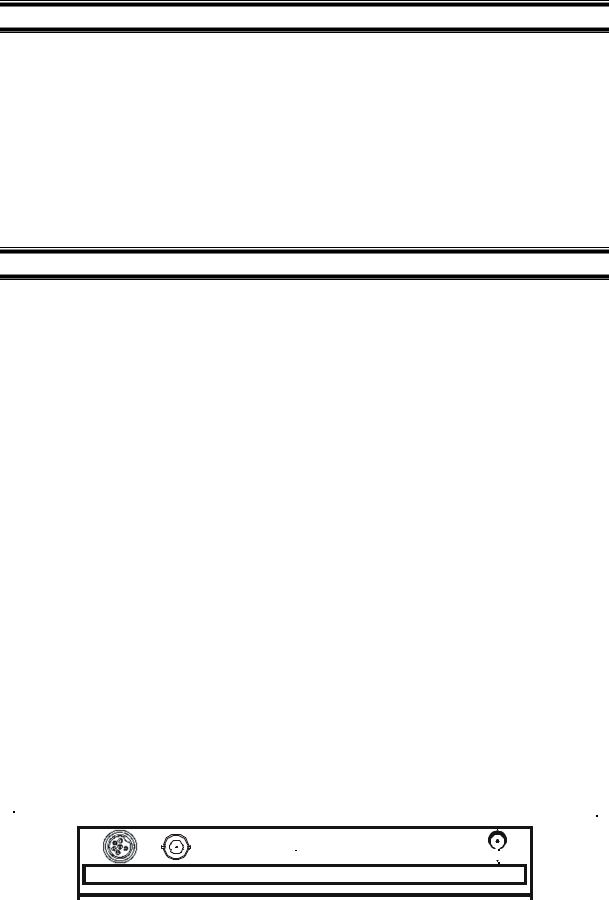
2.4Rear instrument panel
The PC 510 bench meter provides three connectors at the rear of the meters. These connectors are labeled CON/TEMP, pH and DC.
|
|
|
|
|
|
|
|
|
|
|
|
|
|
|
|
|
|
|
|
|
|
|
|
|
|
|
|
|
|
|
|
|
|
|
|
|
|
|
|
CON/TEMP pH |
|
DC |
|
|
|||
|
|
|
|
|
|
|
|
|
|
|
|
|
|
|
|
|
Figure 1 : View of meter rear panel |
|
|
||||
|
|
|
|
|
|
|
|||||
1
Instruction Manual |
PC 510 |
Connector |
Function |
|
CON/TEMP |
For connecting 6-pins conductivity/TDS sensor with built-in temperature sensor to the |
|
meter or optional temperature probe for use with pH electrode (when applicable). |
||
|
Always make sure that the connector is clean and dry. |
|
pH |
For connecting pH sensor with a BNC connector to the meter. Always make sure that |
|
the connector is clean and dry. |
||
|
||
DC |
For connection to the AC power source to the power jack (DC). |
2.5AC/DC adapter
The AC/DC adapter converts the power mains voltage 120/220 VAC to low DC voltage for the PC 510 bench meter operation. Two basic models of adapters are available depending upon power supply specification of each country.
Description |
Order Code |
Voltage |
AC Adapter 120 V |
EC-120-ADA / 35615-07 |
110-120 V, 50-60 Hz |
AC Adapter 220 V |
EC-220-ADA / 35615-08 |
220-240 V, 50-60 Hz |
2.6 Electrodes
Your meter includes two probes:
•pH electrode with BNC connector
•conductivity probe with built-in temperature sensor with a notched 6-pin connector
The temperature sensor built into the conductivity probe will also compensate for pH readings as long as both probes are in your solution at the same time.
If you want to use a “3-in-1” pH probe with a built-in temperature sensor, or if you want to use a separate temperature probe, you will need to disconnect the conductivity probe to allow for connection of the separate temperature sensor.
2.7Electrode holder
The integral electrode holder serves as a handy holder for mounting the pH and conductivity/temperature probes during measurement or when idle.
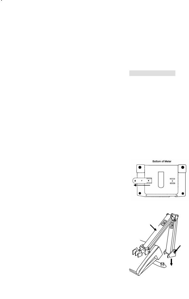
The bench meter’s base plate has a side metal bar to which you can attach an integral swivel electrode holder. You can mount the electrode holder on either right or left side of the meter.
To position the electrode arm:
Use a Philips screwdriver to remove the screw holding the
electrode holder. Slide the side metal bar until the second screw holder.
slot lines up with the original screw hole. Use the screw removed
earlier to secure the electrode holder into position. Note the side
3 KEYPAD FUNCTIONS
metal bar is reversible. If desired, remove screw holding electrode holder base and slide out of brackets. Slide base into brackets on
opposite side and tighten screws. See Figure 2.
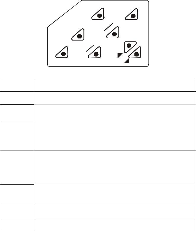
3.1 Keypad
To install electrode arm to the meter:
The PC 510 is equipped with large tactile response keypad for To mount the electrode arm into the metal rod on the side bar, ease of use. All keys have primary function with some keys having align the slot with the metal rod and base of electrode arm. Push secondary functions.
it downwards until it fully sits into position. Avoid using excessive force when fixing or removing. The electrode arm is ready for use.
NOTE: Move the base of electrode holder if you wish to swing the electrode holder about. To prevent the meter form toppling over causing accidental spills, DO NOT swing the body of the electrode holder.
Figure 2: To position electrode arm
Body of Electrode
Holder
Base of
Electrode
Holder
Side Metal Bar
Figure 3: Installing the
electrode arm
2
Instruction Manual |
PC 510 |
T E S
E D O M
|
D |
L |
|
O |
|
H |
|
|
|
|
R |
|
|
|
|
E |
|
E |
|
|
T |
|
|
||
N |
|
|
G |
||
E |
|
|
N |
|
|
|
A |
|
|
||
R |
|
|
|
||
|
|
|
|
|
|
L |
S |
|
A |
|
|
C |
A |
|
E |
|
|
M |
|
|
F F /O N O
ON/OFF
SET
MODE
HOLD
CAL/MEAS
ENTER/RANGE
Figure 4: Keypad
Powers the meter on or off. When meter is switched on, it starts in the mode the meter was last in when powered off.
Enters advanced setup mode. SETUP mode lets you customise meter preferences and defaults, and view calibration and probe data.
Measurement: Press MODE to toggle between pH, mV, conductivity and TDS.
Calibration: In calibration mode, press MODE to access temperature calibration.
Freezes the measured reading. To activate, press HOLD while in measurement mode. To release, press HOLD again.
Note: When auto endpoint feature is switched on, meter automatically holds reading after 5 seconds of stability. The HOLD indicator appears on the display. Press HOLD to release auto endpoint feature.
Toggles between Calibration and Measurement mode. Example: If you are in pH measurement mode, press CAL/MEAS to enter pH calibration mode.
Note: Temperature calibration is available from pH, TDS or Conductivity calibration mode.
In Setup mode: Press CAL/MEAS to return to main menu from sub menus. Press CAL/MEAS again to return to measurement mode from main menu.
ENTER: Press to confirm values in Calibration mode and to confirm selections in Setup mode.
RANGE: Press to switch to manual ranging in Conductivity or TDS mode.
Press |
in Setup mode to scroll up through subgroups. Also lets you increase the values |
in the conductivity, TDS and temperature calibration modes. |
|
Press |
in Setup mode to scroll down through subgroups. Also lets you decrease the |
values in the conductivity, TDS and temperature calibration modes.
3
Instruction Manual |
PC 510 |
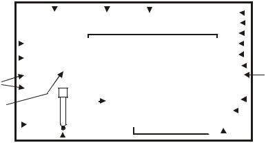
3.2Display
The PC 510 features a large dual display that shows the measured parameter in the primary display, plus temperature in °C or °F in the secondary display. It also features mode annunciators that describe the meter’s functions.
|
|
|
|
|
|
|
|
|
|
|
|
|
|
|
|
|
Primary Display |
|
|
|
|
|
|
|
|
|
|
||||
|
|
|
|
|
1 |
|
|
|
2 |
3 |
|
|
|
|
mV |
|
|
|
|
|
4 |
||||||||||
|
|
|
|
|
|
|
|
|
|
|
|
|
|
|
|
|
|
|
|
|
|
|
|
|
|
|
|
||||
|
|
|
|
|
SETUP |
MEAS |
CAL |
|
|
|
|
|
|
||||||||||||||||||
|
|
|
|
|
|
|
|
|
|
|
|||||||||||||||||||||
|
|
|
|
|
|
|
|
|
% |
|
|
|
|
|
5 |
||||||||||||||||
|
|
|
|
|
|
|
|
|
|
|
|||||||||||||||||||||
|
20 |
|
|
|
READY |
|
|
|
|
|
|
|
|
|
|
|
pH |
|
|
|
6 |
||||||||||
|
|
|
|
|
|
|
|
|
|
|
|
|
|
|
|
|
|
|
|||||||||||||
|
|
|
|
|
|
|
|
|
|
|
|
|
|
|
mS |
|
|
7 |
|||||||||||||
|
|
|
|
|
|
|
|
|
|
|
|
|
|
|
|
|
|||||||||||||||
|
18 |
|
|
|
ON |
|
-8.8.8.8ppm |
10 |
|||||||||||||||||||||||
|
19 |
|
|
|
HOLD |
|
|
|
|
|
|
|
|
|
|
|
|
µS |
|
|
8 |
||||||||||
|
|
|
|
|
|
|
|
|
|
|
|
K = |
|
|
|
|
|
|
|
|
|
ppt |
|
9 |
|||||||
|
|
|
|
|
|
|
|
|
|
|
|
|
|
|
|
|
|
|
|
|
|
|
|
|
|
|
|
|
|
||
|
16 |
|
|
|
OFF |
|
|
|
|
ERR |
|
|
|
|
|
°C °F |
|
11 |
|||||||||||||
|
|
|
|
|
|
|
|
|
|
|
|
|
|
||||||||||||||||||
|
|
|
|
|
|
|
|
|
|
|
|
|
|
|
|
|
|
|
|
||||||||||||
|
|
|
|
|
|
|
|
|
|
|
|
|
|
|
|
|
|
|
|||||||||||||
|
|
|
|
|
|
|
|
|
|
|
|
|
|
|
-1.8.8.8ATC |
|
|
|
|
|
|||||||||||
|
17 |
|
|
|
|
|
|
|
|
|
|
|
|
|
|
|
|
|
|
|
pH |
|
|
|
|
12 |
|||||
|
|
|
|
|
|
|
|
|
|
|
|
|
|
|
|
|
|
|
|
|
|
|
|
|
|
|
|
|
|
|
|
|
|
|
|
|
|
|
|
|
|
|
|
|
|
|
|
|
|
|
|
|
|
|
|
|
|
|
|
||||
|
|
|
|
|
|
|
|
|
|
|
|
|
|
|
|
|
|
|
|
|
|
|
|
|
|
|
|
|
|
|
|
|
|
|
|
|
|
|
|
|
|
|
|
|
|
|
|
|
|
|
|
|
|
|
|
|
|
|
|
|
|
|
|
|
|
|
|
|
|
|
|
|
|
|
15 |
14 |
|
Secondary |
|
Display 13 |
|
|
|
|
|
||||||||||
|
|
|
|
|
|
|
|
|
|
|
|
|
|
|
|
|
|
||||||||||||||
|
|
|
|
|
|
|
|
|
|
|
|
|
|
Figure 5: Full LCD Screen |
|
|
|
|
|
|
|
|
|
|
|||||||
1. |
SETUP mode indicator |
|
|
|
|
|
|
|
8. |
micro-Siemens indicator |
14. |
ERRor indicator |
|||||||||||||||||||
2. |
MEASurement mode indicator |
|
9. |
parts per thousand indicator |
15. |
probe indicator |
|||||||||||||||||||||||||
3. |
CALibration indicator |
|
|
|
|
|
|
|
10. |
parts per million indicator |
16. |
calibration solution indicator |
|||||||||||||||||||
4. |
mV indicator |
|
|
|
|
|
|
|
11. |
temperature indicator |
17. |
cell constant indicator |
|||||||||||||||||||
5. |
% indicator |
|
|
|
|
|
|
|
12. |
pH indicator |
|
|
|
|
|
18. |
ON/OFF indicator |
||||||||||||||
6. |
pH measurement indicator |
|
13. |
Automatic Temperature |
19. |
HOLD indicator |
|||||||||||||||||||||||||
|
|
|
|
|
|
|
|
|
|
|
|
|
|
Compensation (ATC) indicator |
|
|
|
|
|
|
|
|
|
|
|||||||
7. |
milli-Siemens indicator |
|
|
|
|
|
|
|
|
|
|
|
|
|
|
|
|
|
20. |
READY indicator |
|||||||||||
4

Instruction Manual |
PC 510 |
4 PREPARATION
4.1Connecting the Sensor Electrode
4.1.1To connect the pH electrode:
1.Slide the BNC connector of the probe over the BNC connector socket on the meter. Make sure the slots of the connector are in line with the posts of the socket. Rotate and push the connector clockwise until it locks.
2.To remove electrode, push and rotate the connector anti-clockwise. While holding onto the metal part of connector, pull it away from the meter
NOTE: Keep connector dry and clean. Do not touch connector with soiled hands.
CAUTION: Do not pull the probe cord or the probe wires might disconnect.
4.1.2To connect the conductivity/temperature probe:
1.Line up the notch and 6-pins on the probe connector with the holes in the connector located on the top of the meter. Push down and screw the metal sleeve to lock the probe connector into place. See Figure 1 on page 1 for the meter rear panel view.
2.To remove probe, unscrew the metal sleeve and slide up the probe connector. While holding onto the metal sleeve, pull probe away from the meter.
NOTE: Follow the same directions to connect an optional separate temperature element. Keep connector dry and clean. Do not touch connector with soiled hands.
CAUTION: Do not pull on the probe cord or the probe wires might disconnect.
4.2Connecting the A.C. Adapter
1.Before plugging in the A.C. adapter, switch off the meter and the power source of the A.C. adapter. This is a safety precaution that should be adhered to safeguard your meter.
2.The A.C. adapter should have the following settings:
Output voltage: 9 V D.C. Current: 500 mA
NOTE: Ensure that the input mains voltage (110/220/240 V) matches your adapter requirements.
3.Insert the D.C. jack into the socket at rear panel of the meter as shown in Figure 1on page 1.
4.Switch on the power to the adapter, followed by the meter.
5

Instruction Manual |
PC 510 |
5 CALIBRATION
5.1Important information on meter calibration
When you calibrate your meter, old calibration points are replaced on a “point by point” basis in pH, and on a “range by range” basis in conductivity or TDS.
For example:
•pH: if you previously calibrated your meter at pH 4.01, 7.00 and 10.01, and you recalibrate at pH 7.00, the meter retains the old calibration data at pH 4.01 and pH 10.01.
•Conductivity: if you previously calibrated your meter at 1413 µS in the 0 to 1999 µS range and you recalibrate at 1500 µS (which is also in the 0 to 1999µS range), the meter will replace the old calibration data (1413 µS) in that range. The meter will retain all calibration data in other ranges.
•TDS: If you previously calibrated your conductivity meter at 300 ppm in the 0 to 999 ppm range and you re-calibrate at 500 ppm (which is also in the 0 to 999 ppm), the meter will replace the old calibration data (300 ppm) in that range. The meter will retain all calibration data in other ranges.
To view current calibration points:
•pH: Program P1.0 in the SETUP section 8.2 page 38.
•Conductivity & TDS: Program P5.0 in the SETUP section, page 32.
To completely recalibrate your meter, or when you use a replacement probe, it is best to clear old calibration data by resetting the meter.
To reset the meter to its factory defaults:
•pH: Program P4.0 in the SETUP section, page 32.
•Conductivity & TDS: Program P9.0 in the SETUP section, page 38.
NOTE: Resetting the meter will set meter to factory defaults. Conductivity and pH must be reset separately.
For directions on how to calibrate your meter:
•See section 5.3 on page 7 for pH calibration
•See section 5.4 on pages 9 for conductivity calibration
•See section 5.5 on page 11 for TDS calibration
5.2Preparing the meter for calibration
Before starting calibration, make sure you are in the correct measurement mode. When you switch on the meter, the meter starts up in the measurement mode you shut it off in. For example, if you shut the meter off in pH measurement mode, the meter will be in the pH measurement mode when you switch the meter on.
Do not re-use calibration solutions after calibration. Contaminants in the solution can affect the calibration, and eventually the accuracy of the measurements. See section 13 on “Accessories” on page 44 for information on our high quality calibration solutions.
6
Instruction Manual |
PC 510 |
5.3pH calibration
NOTE: We recommend that you perform at least a 2-point calibration using standard buffers that bracket (one above and one below) the expected sample range.
5.3.1Preparing for pH calibration
This meter is capable of up to 5-point pH calibration to ensure accuracy across the entire pH range of the meter. Select from the following buffer options:
•USA: pH 1.68, 4.01, 7.00, 10.01 and 12.45
•NIST: pH 1.68, 4.01, 6.86, 9.18 and 12.45
The meter automatically recognises and calibrates to these standard buffer values, which makes pH calibration faster and easier.
NOTE: Selection of USA or NIST buffer standards must be done prior to calibration. Refer to Section 8.4 on P3.3 on page 29.
5.3.2Before starting
Be sure to remove the protective electrode storage bottle or rubber cap of the probe before calibration or measurement. If the electrode has been stored dry, hydrate the probe in tap water for 10 minutes before calibrating or taking readings to saturate the pH electrode surface and minimise drift.
Wash your probe in de-ionised water after use, and store in electrode storage solution. If storage solution is not available, use pH 4.01 or 7.00 buffer for short term storage. DO NOT store electrode in distilled or de-ionised water.
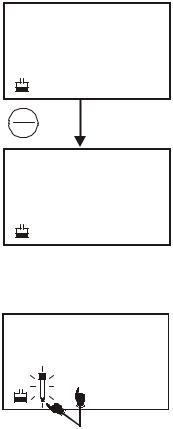
5.3.3To calibrate pH
1.If necessary, press the MODE key to select pH mode. The pH indicator appears in the upper right hand corner of the display.
2.Rinse the probe thoroughly with de-ionised water or rinse solution. Do not wipe the probe as this causes a build-up of electrostatic charge on the glass surface.
3.Dip the probe into the standard calibration buffer. The end of the probe must be completely immersed into the sample. Stir the probe gently to create a homogeneous sample.
NOTE: The temperature element is in the conductivity cell. For temperature compensated readings, dip the conductivity cell or ATC probe into the calibration buffer as well.
4.Press CAL/MEAS to enter pH calibration mode. The CAL indicator will be shown. The primary display will show the measured reading while the smaller secondary display will indicate the pH standard buffer solution.
5.Wait for the measured pH value to stabilise. If the READY indicator has been activated through the Setup, the READY appears when the reading is stable.
6.Press ENTER to confirm calibration. The meter is now calibrated to the current buffer. The lower display automatically scrolls through the remaining buffer options.
MEAS
7.16 pH
°C
22.3 ATC
CAL
MEAS
CAL
pH
7.16
7.00 pH
|
CAL |
READY |
7.16 pH |
|
7.00 pH |
ENTER |
|
RANGE |
|
|
CAL |
READY |
7.00pH |
7.00 pH
Figure 6: pH calibration
•If you are performing multi-point calibration, go to step 7.
7
Instruction Manual
• If you are performing one-point calibration, go to step 9.
7.Rinse the electrode with de-ionised water or rinse solution, and place it in the next pH buffer.
8.Follow steps 5 to 7 for additional calibration points.
9.When calibration is complete, press CAL/MEAS to return to pH measurement mode.
NOTE: To exit from pH calibration mode without confirming calibration, DO NOT press ENTER in step 6. Press CAL/MEAS instead.
If the selected buffer value is not within ±1.0 pH from the measured pH value: the electrode and buffer icon blink and the ERR annunciator appears in the lower left corner of the display.
To limit the number of pH buffer values available during calibration, see section 8.4 Setup P3.2 on page 29.
PC 510
|
CAL |
READY |
4.15 pH |
|
4.01 pH |
ENTER |
|
RANGE |
|
|
CAL |
READY |
4.01 pH |
4.01 pH
Figure 7: Next point calibration for pH 4.01
CAL
0.64pH
ERR 1.68pH
Figure 8: Err message and electrode icon will appear if incorrect buffer is used
8
Instruction Manual |
PC 510 |
5.4Conductivity/TDS calibration
The PC 510 has 5 measuring ranges. You can calibrate 1 point each of the measuring ranges (up to 5 points). If you are measuring values in more than 1 range, make sure to calibrate each of the ranges you are measuring. All new calibration data will over-ride existing stored calibration data for each measuring range you calibrate.
•If you are measuring in ranges near to or greater than 20 mS (10 ppt), or near to or lower than 100 µS (50 ppm), calibrate the meter at least once a week to get specified ±1% Full Scale accuracy.
•If you are measuring in the mid-ranges and you washed the probe in de-ionised water and stored it dry, calibrate the meter at least once a month.
•If you take measurements at extreme temperatures, calibrate the meter at least once a week.
5.4.1Preparing for conductivity/TDS calibration
For best results, select a standard value close to the sample value you are measuring. Alternatively, use a calibration solution value that is approximately 2/3 the Full-Scale value of the measurement range you plan to use. For example, in the 0 to 1999 µS conductivity range, a 1413 µS solution is a good solution for calibration.
See the table below for recommended calibration solution ranges.
Range |
Conductivity |
Recommended Calibration |
TDS Range |
Recommended Calibration |
|
Indicator |
Range |
Solution Range |
Solution Range |
||
|
|||||
|
|
|
|
|
|
r 1 |
0.00 to 19.99 µS |
6.00 to 17.00 µS |
0.00 to 9.99 ppm |
3.00 to 8.50 ppm |
|
|
|
|
|
|
|
r 2 |
0.0 to 199.9 µS |
60.0 to 170.0 µS |
10.0 99.9 ppm |
30.0 to 85.0 ppm |
|
|
|
|
|
|
|
r 3 |
0 to 1999 µS |
600 to 1700 µS |
100 to 999 ppm |
300 to 850 ppm |
|
|
|
|
|
|
|
r 4 |
0.00 to 19.99 mS |
6.00 to 17.00 mS |
1.00 to 9.99 ppt |
3.00 to 8.50 ppt |
|
|
|
|
|
|
|
r 5 |
0.0 to 199.9 mS |
60.0 to 170.0 mS |
10.0 to 200 ppt |
30.0 to 170.0 ppt |
|
|
|
|
|
|
Calibration Solution Ranges
Temperature Coefficient: These meters are factory set to a temperature coefficient of 2.1 % per °C. For most applications this will provide good results. See Program P8.1 on page 37 to set the temperature coefficient to different value. See Addendum 2, “Calculating Temperature Coefficients” to determine the appropriate temperature coefficient for your solution.
Normalisation Temperature: The factory default value for normalisation temperature is 25 °C. If you need to normalise to a value other than 25 °C, see Program P8.2 on page 38.
Do not reuse calibration solutions after calibration. Contaminants in the solution can affect the calibration, and eventually the accuracy of the measurements. Use fresh calibration solution each time you calibrate your meter.
All new calibration data will over-ride existing stored calibration data for each measuring range calibrated.
9
Instruction Manual
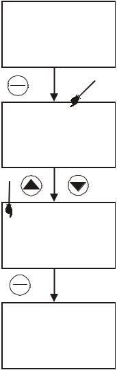
Calibrating for Conductivity:
1.If necessary, press the MODE key to select conductivity mode.
2.Rinse the probe thoroughly with de-ionised water or a rinse solution, then rinse with a small amount of calibration standard.
3.If necessary, ensure that the probe’s yellow probe guard is attached. Dip the probe into the calibration standard. Immerse the probe tip beyond the upper steel band. Stir the probe gently to create a homogeneous sample.
4.Wait for the measured conductivity value to stabilise. If the READY indicator has been activated (SETUP program P7.1 – see page 31), the READY annunciator lights when the reading is stable.
5.Press CAL/MEAS to enter conductivity or TDS calibration mode. The CAL indicator will appear in the upper right corner of the display.
6. Press the or key to change the value on the primary display to match the value of the calibration standard.
7.Press ENTER to confirm calibration value. The meter returns to the MEAS (measurement) mode.
8.Repeat steps 1 to 7 for other measuring ranges.
NOTES: When entering calibration mode, the meter will display the factory default value. If the meter was previously calibrated, the display may “jump” to the factory default / uncalibrated value when switching from measurement to calibration mode.
To exit from Conductivity calibration mode confirming calibration, DO NOT press the ENTER key in step 7. Press CAL/MEAS instead.
This will retain the meter’s old calibration data in the measuring range of the calibration.
You can offset the conductivity reading up to ±40% from default setting. If your measured value differs by more than ±40% clean or replace probe as needed, or use a calibration standard with a higher value as required.
PC 510
MEAS
1409 µS
°C
22.3 ATC
CAL
MEAS
CAL
1409µS
°C
22.3 ATC
|
CAL |
|
READY |
1413 µS |
|
|
1409 |
|
ENTER |
|
|
RANGE |
|
|
|
MEAS |
|
READY |
1413µS |
|
|
22.3 |
°C |
|
ATC |
|
Figure 9: Conductivity
calibration
A wide selection of high-quality calibration standards is available. See page 44 for more information.
10
Instruction Manual |
PC 510 |
5.5TDS Calibration
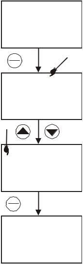
5.5.1Calibrating for TDS directly
The factory default setting for TDS conversion factor is 0.5. If your solution has a different TDS factor, you can improve calibration accuracy by setting the TDS factor prior to calibration. See Program P7.4 on page 36 for directions.
1.If necessary, press the MODE key to select TDS mode.
2.Rinse the probe thoroughly with de-ionised water or a rinse solution, then rinse with a small amount of calibration standard.
3.If necessary, ensure that the probe’s yellow probe guard is attached. Dip the probe into the calibration standard. Immerse the probe tip beyond the upper steel band. Stir the probe gently to create a homogeneous sample. Allow time for the reading to stabilise.
4.Press the CAL/MEAS to enter TDS calibration mode. The CAL indicator will appear in the upper right corner of the display.
5. Press the or key to change the value on the primary display to match the value of the calibration standard.
6.Press ENTER to confirm the calibration value. The meter returns to the MEAS (measurement) mode. See Figure 10.
7.Repeat steps 1 to 6 for other measuring ranges.
NOTES:
To exit from TDS Calibration mode without confirming calibration, DO NOT press ENTER key in step 6. Press CAL/MEAS instead. This will retain the meter’s old calibration data in the measuring range of the calibration. You can offset the TDS reading up to ±40% from the
default setting. If your measured value differs by more than ±40%, clean or replace probe as needed, or use a calibration standard with a higher value as required.
MEAS
265 ppm
°C
25.8 ATC
CAL
MEAS
CAL
265 ppm
°C
25.8 ATC
CAL
READY 300 ppm
265
ENTER
RANGE
MEAS
READY 300 ppm
°C
25.8 ATC
Figure 10: TDS calibration
11
Instruction Manual |
PC 510 |
5.6Calibration with Conductivity Standard and TDS factor
The concentration of salts dissolved in solution increases the conductivity of that solution. This relationship varies from salt to salt and is roughly linear over a given range for a given salt.
The TDS conversion factor is the number used by the meter to convert from conductivity to TDS.
Instead of calibrating for TDS directly (described above), you can calibrate the PC 510 bench meter by:
1.Calibrating to conductivity standards (as described above) and then
2.Entering the appropriate TDS conversion factor into the meter.
To determine the conductivity to TDS conversion factor for your solution:
•Addendum 1 on page 47 lists some commonly used conversion factors.
•Addendum 2 on page 48 describes how to calculate the TDS conversion factor for other solutions.
Enter the TDS conversion factor into your meter as described under Section 8.8, in Program P7.4, Setting the TDS Factor on page 36.
12
Instruction Manual |
PC 510 |
5.7Temperature Calibration
The conductivity electrode (EC-CONSEN91W / 35608-50) supplied has a built-in temperature sensor. Alternatively, a separate temperature sensing element can be used (such as temperature probe EC-WPPHTEM-01W / 35618-05), or a “3-in-1” pH/Temperature combination electrode with ATC connection.
The conductivity probe is factory calibrated. Temperature calibration is recommended only if you suspect temperature errors may have occurred over a long period of time, or if you have a replacement probe.
Temperature calibration is accessible during pH, conductivity or TDS calibration.
MEAS
7.16 pH
°C
22.3 ATC
CAL
MEAS
CAL
pH
7.16
7.00 pH
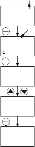
Temperature Calibration
1.Make sure the conductivity electrode, or temperature probe, or “3-in-1” electrode is attached to the 6-pin connector.
2.Switch the meter on.
3.Press the CAL/MEAS key to enter calibration mode (either from pH or conductivity mode). The CAL indicator will appear above the primary display.
MODE
CAL
22.3
22.3 °C
ATC
4.While in pH (or conductivity or TDS) calibration mode, press the MODE key to enter temperature calibration mode. The primary display shows the last set temperature value and the secondary display shows the temperature reading with zero offset.
5.Dip the ATC probe into a solution of known temperature (i.e. a temperature bath). Allow time for the temperature probe to stabilise.
CAL
22.0
22.3 °C
ATC
ENTER
RANGE
6. Scroll with the |
or |
key to set the correct temperature value (i.e. the |
|
temperature of the temperature bath). You can adjust the reading by 0.1 |
READY |
||
°C or °F increments. |
|
|
|
7.Once you have selected the correct temperature press the ENTER key. The meter automatically returns to measurement mode.
Figure 12:
NOTES:
MEAS
7.16 pH
°C
22.0 ATC
Temperature calibration in pH mode
•You can offset the temperature reading up to ±5° from default reading.
•To exit this program without confirming the temperature calibration value, DO NOT press ENTER, press CAL/MEAS in step 7 instead.
13
 Loading...