


Instruction Manual
CON 11 & CON 110
Handheld Conductivity/TDS/Temperature/RS232C Meter
68X361303 Rev. 1 - 12/03
Technology Made Easy ...

Preface
This manual serves to explain the use of the CON 11/110 Conductivity/TDS handheld meters. It functions as a handy reference step by step guide to help you operate the meter. It is written to cover as many anticipated application of the CON
11/110 meters as possible. If there are doubts in the use of the meter, please do not hesitate to contact the nearest Authorised Distributor.
Eutech Instruments / Oakton Instruments cannot accept any responsibility for damage or malfunction of the meter caused by improper use of the instruments.
The information presented in this manual is subjected to change without notice as improvements are made, and does represent a commitment on the part of Eutech Instruments Pte Ltd / Oakton Instruments.
Copyright © 2003 All rights reserved.
Eutech Instruments Pte Ltd
Oakton Instruments
Rev 1 - 12/03

Table of Contents
1 |
INTRODUCTION ....................................................................................................................................... |
1 |
|
2 DISPLAY AND KEYPAD FUNCTIONS.................................................................................................. |
2 |
||
|
2.1 |
DISPLAY ............................................................................................................................................... |
2 |
|
2.2 |
KEYPAD ................................................................................................................................................ |
3 |
3 |
PREPARATION.......................................................................................................................................... |
5 |
|
|
3.1 |
INSERTING THE BATTERIES ................................................................................................................... |
5 |
|
3.2 |
CONDUCTIVITY ELECTRODE INFORMATION.......................................................................................... |
6 |
|
3.3 |
CONNECTING THE ELECTRODE TO THE METER ...................................................................................... |
7 |
|
3.4 |
ATTACHING THE ELECTRODE HOLDER TO THE METER ......................................................................... |
8 |
|
3.4.1 Inserting the electrode into the electrode holder ............................................................................. |
8 |
|
|
3.5 |
CONNECTING THE AC/DC ADAPTER .................................................................................................... |
9 |
|
3.6 |
CONNECTING THE RS232C CABLE (ONLY FOR CON 110) ................................................................... |
9 |
|
3.6.1 |
RS232C Configuration .................................................................................................................. |
10 |
4 |
CALIBRATION ........................................................................................................................................ |
11 |
|
|
4.1 |
IMPORTANT INFORMATION ON METER CALIBRATION......................................................................... |
11 |
|
4.2 |
PREPARING THE METER FOR CALIBRATION ........................................................................................ |
12 |
|
4.3 |
TEMPERATURE CALIBRATION ............................................................................................................. |
13 |
|
4.4 |
SELECTION OF AUTOMATIC OR MANUAL CALIBRATION ..................................................................... |
14 |
|
4.5 |
AUTOMATIC CALIBRATION (FOR CONDUCTIVITY CALIBRATION ONLY) ............................................ |
15 |
|
4.6 |
MANUAL CALIBRATION (FOR CONDUCTIVITY & TDS CALIBRATION) ............................................... |
17 |
|
4.7 |
TDS CALIBRATION ............................................................................................................................. |
18 |
|
4.7.1 Calibrating for TDS Using Conductivity Standards & adjusting TDS factor ............................... |
18 |
|
|
4.7.2 Setting the TDS Conversion Factor............................................................................................... |
18 |
|
|
4.7.3 Calibrating for TDS using TDS standards .................................................................................... |
19 |
|
5 |
MEASUREMENT ..................................................................................................................................... |
20 |
|
|
5.1 |
AUTOMATIC TEMPERATURE COMPENSATION ..................................................................................... |
20 |
|
5.2 |
MANUAL TEMPERATURE COMPENSATION .......................................................................................... |
21 |
|
5.2.1 Setting the manual temperature compensation value.................................................................... |
22 |
|
|
5.3 |
TAKING MEASUREMENTS ................................................................................................................... |
23 |
|
5.3.1 Taking measurements with READY indicator selected on ............................................................ |
23 |
|
|
5.3.2 Taking measurements with the Auto HOLD feature selected on................................................... |
23 |
|
|
5.4 |
USING MANUAL RANGING FUNCTION ................................................................................................ |
24 |
|
5.4.1 |
Selecting manual range................................................................................................................. |
24 |
|
5.5 |
HOLD FUNCTION ............................................................................................................................... |
25 |
6 |
MEMORY FUNCTION............................................................................................................................ |
26 |
|
|
6.1 |
MEMORY INPUT .................................................................................................................................. |
26 |
|
6.2 |
MEMORY RECALL............................................................................................................................... |
27 |
7 PRINT FUNCTION (FOR CON 110 ONLY) ......................................................................................... |
28 |
||
|
7.1 |
USING CON 110 METER WITH PRINTER OR COMPUTER...................................................................... |
28 |
|
7.2 |
SENDING DATA TO COMPUTER OR PRINTER ....................................................................................... |
29 |
|
7.2.1 Printing Current Data Manually................................................................................................... |
30 |
|
|
7.2.2 Print Data on Timed Interval ........................................................................................................ |
30 |
|
|
7.2.3 Print Data from Stored Memory ................................................................................................... |
32 |
|
8 |
ADVANCED SETUP FUNCTION .......................................................................................................... |
34 |
|
|
8.1 |
ADVANCED SETUP MODE OVERVIEW ............................................................................................... |
36 |
|
8.2 |
P1.0: UNIT CONFIGURATION (COF).................................................................................................... |
38 |
|
8.2.1 P1.1: Selection of READY and Auto HOLD function.................................................................... |
38 |
|
|
8.2.2 P1.2: Selection of °C or °F ........................................................................................................... |
39 |
|
|
8.2.3 P1.3: Selection of Automatic or Manual Temperature Compensation.......................................... |
40 |
|
|
8.2.4 P1.4: Selection of TDS Conversion Factor ................................................................................... |
41 |
|
|
|
|
|

|
8.3 |
....................................................................................................P2.0: VIEWING CALIBRATION DATA |
42 |
|
|
8.4 |
P3.0 VIEWING ELECTRODE DATA ....................................................................................................... |
43 |
|
|
8.5 |
P4.0: AUTO OFF.................................................................................................................................. |
44 |
|
|
8.6 |
P5.0: RESET TO FACTORY DEFAULTS .................................................................................................. |
45 |
|
|
8.6.1 |
|
P5.1: Calibration Reset................................................................................................................. |
45 |
|
8.6.2 |
|
P5.2: User Reset............................................................................................................................ |
46 |
|
8.7 |
P6.0: MEMORY CLEAR........................................................................................................................ |
47 |
|
|
8.8 |
P7.0: TEMPERATURE........................................................................................................................... |
48 |
|
|
8.8.1 P7.1: Setting the temperature coefficient ...................................................................................... |
48 |
||
|
8.8.2 P7.2: Setting the normalisation temperature ................................................................................ |
49 |
||
|
8.9 |
P8.0: SELECTION OF CELL CONSTANT ................................................................................................. |
50 |
|
|
8.10 |
P9.0: AUTOMATIC AND SINGLE POINT CALIBRATION ......................................................................... |
51 |
|
|
8.10.1 |
P9.1: Selection of Automatic or Manual Calibration............................................................... |
51 |
|
|
8.10.2 |
P9.2: Selection of Single or Multi Point Calibration ............................................................... |
52 |
|
9 |
CYBERCOMM PORTABLE DAS (FOR CON 110 ONLY)................................................................. |
53 |
||
|
9.1 |
SYSTEM REQUIREMENTS..................................................................................................................... |
53 |
|
|
9.2 |
LOADING CYBERCOMM PORTABLE DAS............................................................................................ |
53 |
|
|
9.3 |
RUNNING CYBERCOMM PORTABLE .................................................................................................... |
59 |
|
|
9.3.1 |
|
Buttons & Check-Box.................................................................................................................... |
60 |
|
9.3.2 |
|
Menu.............................................................................................................................................. |
61 |
|
9.3.3 |
|
Communication Settings................................................................................................................ |
62 |
|
9.4 |
CAPTURING AND PRINTING DATA INTO COMPUTER USING DATA ACQUISITION................................ |
63 |
|
|
9.5 |
TROUBLE-SHOOTING GUIDE ............................................................................................................... |
64 |
|
10 |
ELECTRODE CARE AND MAINTENANCE....................................................................................... |
65 |
||
11 |
ERROR MESSAGES................................................................................................................................ |
66 |
||
12 |
TROUBLE SHOOTING........................................................................................................................... |
67 |
||
13 |
LIST OF ACCESSORIES ........................................................................................................................ |
68 |
||
|
13.1 |
REPLACEMENT METER AND METER ACCESSORIES.............................................................................. |
68 |
|
|
13.2 |
CALIBRATION SOLUTIONS .................................................................................................................. |
68 |
|
14 |
FACTORY DEFAULT SETTINGS ........................................................................................................ |
69 |
||
|
14.1 |
CON 11 FACTORY DEFAULT SETTING................................................................................................ |
69 |
|
|
14.2 |
CON 110 FACTORY DEFAULT SETTING .............................................................................................. |
70 |
|
15 |
SPECIFICATIONS ................................................................................................................................... |
71 |
||
16 |
CALIBRATION TIPS............................................................................................................................... |
73 |
||
17 |
CALCULATING TDS CONVERSION FACTORS............................................................................... |
73 |
||
18 |
CALCULATING TEMPERATURE COEFFICIENTS ........................................................................ |
74 |
||
19 |
WARRANTY............................................................................................................................................. |
75 |
||
20 |
RETURN OF ITEMS................................................................................................................................ |
75 |
||

Instruction Manual |
CON 11/110 |
1 INTRODUCTION
Thank you for selecting the CON 11/110 Conductivity/TDS handheld meter. These meters are microprocessor-based instruments and are designed to be handy, capable of allowing one-hand operation. Each has a large customised LCD for clear and easy reading. It also has user-friendly features, all of which are accessible through the splash-proof membrane keypad. It is a unique and intelligent instrument and has the capability to cater to the preferences of the discerning individual. You have one of the two models:
•CON 11 meter
•CON 110 meter
Your meter includes a conductivity electrode (ECCONSEN91W electrode constant K = 1.0) with built-in temperature sensor and batteries.
The basic model is the CON 11 which is capable of measuring Conductivity, TDS and Temperature.
The deluxe model is the CON 110 which measures the Conductivity, TDS and
Temperature and has a RS232C port that allows the meter to be connected to a computer or a printer via a cable for transferring data.
For power requirements, you can either use the 4 AAA-sized batteries or an AC/DC power adapter (sold separately).
Please read this manual thoroughly before operating your meter.
1
Instruction Manual |
CON 11/110 |
2 DISPLAY AND KEYPAD FUNCTIONS
2.1Display
The LCD has a primary and secondary display.
•The primary display shows the measured Conductivity/TDS values.
•The secondary display shows the measured temperature.
The display also shows error messages, keypad functions and program functions.
Primary Display
1 |
2 |
3 |
4 |
|
|
|
|
|
SETUP MEAS |
CAL MEM |
|
|
|
|
|
|
|
|
|
|
|
|
|||||||||||||||
18 |
|
|
|
|
READY |
|
|
1.8.8.8 |
mS |
|
|
5 |
|
||||||||||||||||||||
|
|
|
|
|
|
|
|||||||||||||||||||||||||||
15 |
|
|
|
|
ON |
|
|
µS |
|
|
|
|
|
6 |
|
||||||||||||||||||
17 |
|
|
|
|
HOLD |
|
K = |
|
|
|
|
|
|
|
|
ppt |
7 |
|
|||||||||||||||
16 |
|
|
|
|
OFF |
|
|
|
|
|
1.8.8.8 |
|
|
|
ppm |
|
|
|
|
|
8 |
|
|||||||||||
|
|
|
|
|
|
|
|
|
|
|
|
|
|
|
|
|
|
|
|
|
|
||||||||||||
14 |
|
|
|
|
|
|
|
|
|
|
ERR |
|
|
|
°C °F |
|
9 |
|
|||||||||||||||
|
|
|
|
|
|
|
|
|
|
|
|
|
|
|
|||||||||||||||||||
|
|
|
|
|
|
|
|
|
|
|
|
|
|
|
|
|
|
|
|||||||||||||||
|
|
|
|
|
|
|
|
|
|
|
|
|
|
|
|
|
|
||||||||||||||||
|
|
|
|
|
|
|
|
|
|
|
|
|
|
|
|
|
ATC |
|
|
|
|
|
|||||||||||
|
|
|
|
|
|
|
|
|
|
|
|
|
|
|
|
|
|
|
|
|
|
|
|
|
|
|
|
|
|
|
|
|
|
|
|
|
|
|
|
|
|
|
|
|
|
|
|
|
|
|
|
|
|
|
|
|
|
|
|
|
|
|
|||||
|
|
|
|
|
|
|
|
|
|
|
|
|
|
|
|
|
|
|
|
|
|
|
|
|
|
|
|
|
|
|
|
|
|
|
|
|
|
|
|
|
|
|
|
|
|
|
|
|
|
|
|
|
|
|
|
|
|
|
|
|
|
|
|
|
|
|
|
|
|
|
|
|
|
|
|
|
|
|
|
|
|
|
|
|
|
|
|
|
|
|
|
|
|
|
|
|
|
|
|
|
|
|
|
|
|
|
13 12 |
11 |
|
|
|
|
|
|
|
|
10 |
|
|
|
|
|
|
|
|||||||||||
|
|
|
|
|
|
|
|
|
|
|
|
|
|
|
|
|
|
|
|
||||||||||||||
|
|
|
|
|
|
|
|
|
|
|
|
|
|
|
|
|
|
Secondary Display |
|
|
|
|
|
||||||||||
|
|
|
|
|
|
|
|
|
|
|
|
|
|
Figure 1: Active LCD display |
|
|
|
|
|
|
|
|
|
|
|
|
|||||||
|
|
|
|
|
|
|
|
|
|
|
|
|
|
|
|
|
|
|
|
|
|
||||||||||||
1. SETUP - Setup mode |
|
|
7. ppt - Parts per |
thousand |
|
|
|
|
|
|
|
|
|
|
|
|
|
|
|||||||||||||||
|
|
|
|
|
|
|
|
|
|
|
|
|
|
|
|
||||||||||||||||||
indicator |
|
|
|
|
|
|
|
|
|
|
indicator |
|
|
13. |
|
|
|
|
- Electrode indicator |
|
|||||||||||||
|
|
|
|
|
|
|
|
|
|
|
|
|
|
|
|
|
|
|
|
|
|
|
|
|
|||||||||
|
|
|
|
|
|
|
|
|
|
|
|
|
|
|
|
|
|
|
|
|
|||||||||||||
2. MEAS - Measurement |
|
|
8. ppm - Parts per million |
14. |
|
|
|
|
- Calibration solution indicator |
|
|||||||||||||||||||||||
|
|
|
|
|
|
|
|||||||||||||||||||||||||||
|
|
|
|
|
|
|
|||||||||||||||||||||||||||
mode indicator |
|
|
|
|
|
|
|
|
|
|
indicator |
|
|
|
|
|
|
|
|||||||||||||||
|
|
|
|
|
|
|
|
|
|
|
|
|
|
|
|
|
|||||||||||||||||
|
|
|
|
|
|
|
|
|
|
|
|
|
|
|
|
|
|
|
|
|
|
|
|
|
|
||||||||
|
|
|
|
|
|
|
|
|
|||||||||||||||||||||||||
3. CAL - Calibration mode |
|
|
9. °C°F - Temperature indicator |
15. ON – READY/Auto HOLD set up |
|
||||||||||||||||||||||||||||
indicator |
|
|
|
|
|
|
|
|
|
|
|
|
|
|
|
|
|
|
|
|
enable indicator. |
|
|||||||||||
|
|
|
|
|
|
|
|
|
|
|
|
|
|
|
|
|
|
|
|
OFF – READY set up disable indicator |
|
||||||||||||
4. MEM - Memory recall |
|
|
10. ATC - Automatic |
16. K = - Cell Constant indicator. |
|
||||||||||||||||||||||||||||
mode indicator |
|
|
|
|
|
|
|
|
|
|
Temperature |
|
|
|
|
|
|
|
|
|
|
|
|
|
|
||||||||
|
|
|
|
|
|
|
|
|
|
|
|
|
|
|
Compensation indicator |
|
|
|
|
|
|
|
|
|
|
|
|
|
|
||||
5. ms - Mill siemens |
|
|
11. ERR - Error indicator |
17. HOLD – Hold indicator |
|
||||||||||||||||||||||||||||
indicator |
|
|
|
|
|
|
|
|
|
|
|
|
|
|
|
|
|
|
|
|
|
|
|
|
|
|
|
|
|
||||
|
|
|
|
|
|
|
|
|
|
|
|
|
|
|
|
|
|
|
|
||||||||||||||
6. µs - Micro siemens |
|
|
|
|
|
|
|
|
|
|
|
|
|
|
|
18. |
|
READY – Ready indicator |
|
||||||||||||||
|
|
|
|
|
|
|
|
|
|
|
|
|
|
|
|
|
|||||||||||||||||
indicator |
|
|
12. |
|
|
|
|
- Low battery indicator |
|
|
|
|
|
|
|
|
|
|
|
|
|
|
|||||||||||
|
|
|
|
|
|
|
|
|
|
|
|
|
|
|
|
|
|
|
|
|
|
|
|
||||||||||
|
|
|
|
|
|
|
|
|
|
|
|
|
|
|
|
|
|
|
|
|
|
|
|
|
|||||||||
|
|
|
|
|
|
|
|
|
|
|
|
|
|
|
|
|
|
|
|
|
|
|
|
|
|
|
|
|
|
|
|
|
|
2

Instruction Manual |
CON 11/110 |
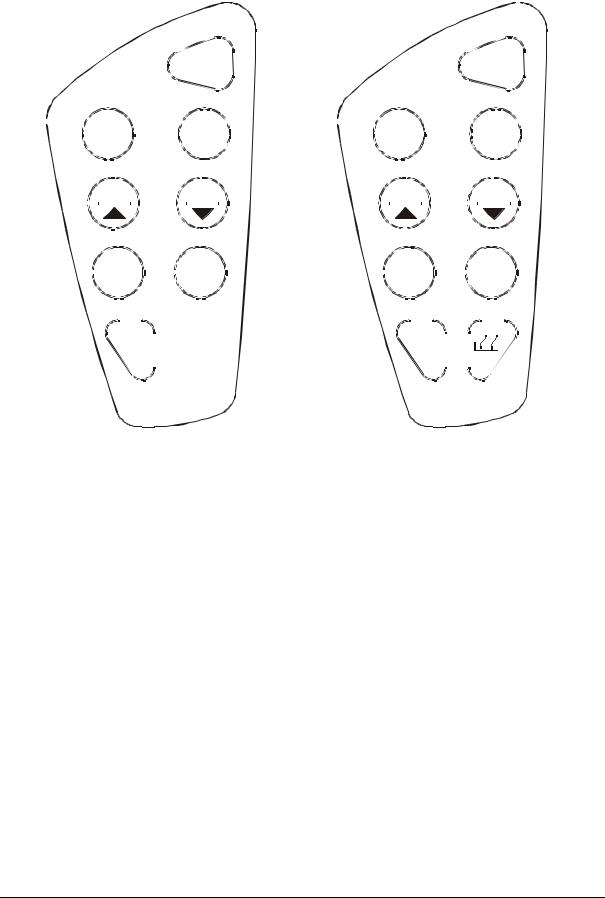
2.2Keypad
A large membrane keypad with tactile feedback makes the instruments easy to use
(Figure 2). Each button, when pressed, has a corresponding graphic indicator on the LCD. Some button has several functions depending on its mode of operation.
|
|
KEY |
|
FUNCTION |
|||
|
|
|
ON |
|
• ON/OFF - Powers on and shuts off the meter. The meter will start in the |
||
|
|
|
|
measurement mode it was in when last switched off. |
|||
|
|
|
OFF |
||||
|
|
|
|
|
|||
|
|
|
|
|
|
|
|
|
|
CAL |
|
|
• CAL - Activates the Conductivity or TDS calibration mode and when used |
||
|
|
|
|
with the MODE key, it activates the temperature calibration mode. |
|||
|
|
MEAS |
|||||
|
|
|
• MEAS - Allows return to measurement mode when canceling or |
||||
|
|
|
|
|
|
|
|
|
|
|
|
|
|
|
terminating any operation. |
|
|
|
|
|
|
|
• HOLD - Activates/Deactivates freezing of the measured reading while in |
|
|
HOLD |
|
measurement mode. |
|||
|
|
|
• ENTER - Confirms the calibration values in Calibration mode and the |
||||
|
ENTER |
|
|||||
|
|
selection in SETUP and Print Function mode. |
|||||
|
|
|
|
|
|
|
|
|
|
|
|
|
|
|
Scroll through the memory location and the stored data during memory |
|
|
|
|
|
|
|
recall. |
|
|
|
MI |
|
• MI (Memory Input) - Captures the measured readings of the Conductivity |
||
|
|
|
|
or TDS with its corresponding temperature values and stores them in |
|||
|
|
|
|
|
|
|
|
|
|
|
|
|
|
|
the memory. |
|
|
|
MR |
|
|
|
• MR (Memory Recall) - Retrieves the stored data from memory. |
|
|
|
|
|
• ▲▼ - Sets the calibration values during the manual Conductivity, TDS |
||
|
|
|
|
|
|
|
and Temperature calibration. |
Scrolls through each SETUP and its sub group menu.
Scroll through Print Function menu and its parameters.
|
|
|
• SETUPActivates the parameter setting menu to allow you to customise |
|
SETUP |
meter configuration, view calibration points and electrode offset data, |
|||
|
|
|
select auto power off, reset meter, clear memory, set temperature |
|
|
|
|
coefficient and normalisation temperature, select electrode cell |
|
|
|
|
constants and set auto & single point calibration selections. |
|
|
|
|
• MODE - Select the measurement parameter option between Conductivity |
|
MODE |
and TDS. When used during Conductivity or TDS calibration mode, it |
|||
|
|
|
activates the temperature calibration mode. |
|
|
|
|
|
|
|
|
|
• RANGE – Allows entry to Manual range selection. |
|
RANGE |
||||
|
||||
|
|
|
|
|
• PRINT - Allows transfer of current measurement or stored data to either the printer or the computer.
(CON110 only)
3
Instruction Manual |
CON 11/110 |
||
|
|
|
|
|
|
|
|
|
|
|
|
|
|
|
|
|
|
|
|
|
|
|
|
|
|
|
|
|
|
|
|
|
ON |
|
|
|
|
|
|
|
|
|
|
|
|
|
|
|
|
|
|
|
ON |
|||||||||||||||||||||
|
|
|
|
|
|
|
|
|
|
|
|
|
|
|
|
|
|
|
|
|
|
|
|
|
OFF |
|
|
|
|
|
|
|
|
|
|
|
|
|
|
|
|
|
|
|
|
OFF |
|
|
||||||||||||||||||
|
|
|
|
|
|
|
|
|
|
|
|
|
|
|
|
|
|
|
|
|
|
|
|
|
|
|
|
|
|
|
|
|
|
|
|
|
|
|
|
|
|
|||||||||||||||||||||||||
|
|
|
|
|
|
|
|
|
|
|
|
|
|
|
|
|
|
|
|
|
|
|
|
|
|
|
|
|
|
|
|
|
|
|
|
|
|
|||||||||||||||||||||||||||||
|
|
|
|
|
|
|
|
CAL |
|
|
|
|
|
|
|
HOLD |
|
|
|
CAL |
|
HOLD |
||||||||||||||||||||||||||||||||||||||||||||
|
|
|
|
|
|
|
||||||||||||||||||||||||||||||||||||||||||||||||||||||||||||
|
|
|
|
|
|
MEAS |
|
|
|
|
|
|
|
|
ENTER |
|
|
MEAS |
|
|
|
|
|
|
|
|
ENTER |
|||||||||||||||||||||||||||||||||||||||
|
|
|
|
|
|
|
|
|
|
|
|
|
|
|||||||||||||||||||||||||||||||||||||||||||||||||||||
|
|
|
|
|
|
|
|
|
|
|
|
|
|
|
|
|
|
|
|
|
|
|
|
|
|
|
|
|
|
|
|
|
|
|
|
|
|
|
|
|
|
|
|
|
|
|
|
|
|
|
|
|
|
|
|
|
|
|
|
|
||||||
|
|
|
|
|
|
|
|
|
|
|
|
|
|
|
|
|
|
|
|
|
|
|
|
|
|
|
|
|
|
|
|
|
|
|
|
|
|
|
|
|
|
|
|
|
|
|
|
|
|
|
|
|
|
|
|
|
|
|
|
|||||||
|
|
|
|
|
|
|
|
|
MI |
|
|
|
|
|
|
|
|
|
MR |
|
|
|
|
MI |
|
|
|
MR |
|
|||||||||||||||||||||||||||||||||||||
|
|
|
|
|
|
|
|
|
|
|
|
|
|
|
|
|
|
|
|
|
|
|
|
|
|
|
|
|
|
|
|
|
|
|
|
|
|
|
|
|
|
|
|
|
|
|
|
|
|
|
|
|
|
|
|
|
|
|||||||||
|
|
|
|
|
|
|
|
SETUP |
|
|
|
|
|
|
MODE |
|
|
SETUP |
|
|
|
|
MODE |
|||||||||||||||||||||||||||||||||||||||||||
|
|
|
|
|
|
|
|
|
|
|
|
|||||||||||||||||||||||||||||||||||||||||||||||||||||||
|
|
|
|
|
|
|
|
|
|
|
|
|
|
|
|
|
|
|
|
|
|
|
|
|
|
|
|
|
|
|
|
|
|
|
|
|
|
|
|
|
|
|
|
|
|
|
|
|
|
|
|
|
|
|
|
|
|
|
|
|
|
|
|
|
|
|
|
|
|
|
|
|
|
|
|
|
|
|
|
|
|
|
|
|
|
|
|
|
|
|
|
|
|
|
|
|
|
|
|
|
|
|
|
|
|
|
|
|
|
|
|
|
|
|
|
|
|
|
|
|
|
|
|
|
|
|
|
|
|
|
|
|
|
|
|
|
|
|
|
|
|
|
|
RANGE |
|
|
|
|
|
|
|
|
|
|
|
|
|
|
|
|
|
|
|
|
|
|
|
|
|
RANGE |
|
|
|
|
|
|
|
|
|
|
|
|
|
|
|
|
|
|
||||||||||||
|
|
|
|
|
|
|
|
|
|
|
|
|
|
|
|
|
|
|
|
|
|
|
|
|
|
|
|
|
|
|
|
|
|
|
|
|
|
|
|
|
|
|
|
|
|
|
|
|
||||||||||||||||||
|
|
|
|
|
|
|
|
|
|
|
|
|
|
|
|
|
|
|
|
|
|
|
|
|
|
|
|
|
|
|
|
|
|
|
|
|
|
|
|
|
|
|
|
|
|
|
|
|
|
|
|
|
|
|
|
|
|
|
|
|
|
|
|
|
|
|
|
|
|
|
|
|
|
|
|
|
|
|
|
|
|
|
|
|
|
|
|
|
|
|
|
|
|
|
|
|
|
|
|
|
|
|
|
|
|
|
|
|
|
|
|
|
|
|
|
|
|
|
|
|
|
|
|
|
|
|
|
|
|
|
|
|
|
|
|
|
|
|
|
|
|
|
|
|
|
|
|
|
|
|
|
|
|
|
|
|
|
|
|
|
|
|
|
|
|
|
|
|
|
|
|
|
|
|
|
|
|
|
|
|
|
|
|
|
|
|
|
|
|
|
|
|
|
|
|
|
|
|
|
|
Keypad for CON 11 meter |
Keypad for CON 110 meter |
Figure 2: CON 11 and CON 110 keypads
4

Instruction Manual |
CON 11/110 |
3 PREPARATION
3.1Inserting the Batteries
This meter is packaged with 4 “AAA” alkaline batteries required for its operation. To insert the batteries into the meter, follow the procedure outlined below.
1.Open the battery compartment by pressing down the catch of the battery cover.
2.Insert the batteries correctly according to the marked polarity of the battery compartment.
3.Close the battery cover, ensuring the catch is locked in position.
Your hand held meter is now ready for operation.
LR03 'AAA' (AM4)
MADE IN S'PORE
Figure 4: Note Battery
Polarity
Figure 3: Open Battery Cover
5
Instruction Manual |
CON 11/110 |
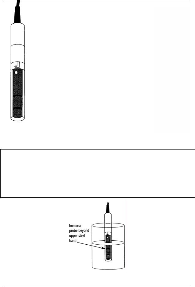
3.2Conductivity Electrode Information
Your meter includes a conductivity electrode (Part No: EC-
CONSEN91W/ 35608-50) Ultem / Stainless Steel electrodes with an electrode constant of K = 1.0. This conductivity / TDS electrode features a built-in temperature sensor for Automatic Temperature
Compensation (ATC). It has a specially designed housing that provides fast temperature response and reduces air bubble entrapment, which makes it easy to obtain accurate, stable readings.
Wetted parts include:
1.Polyetherimide PEI (Ultem®)
2.Polybutylene Terephthalate PBT (Valox®)
3.Stainless Steel (SS 304)
Proper use of electrode is essential to ensure that the optimum measurement is taken in a short time.
The removable protective plastic electrode guard is meant for simple periodic maintenance and it must be kept in tact during measurement and calibration.
Always immerse the electrode beyond upper steel band. |
|
|
Figure 5: Conductivity |
||
|
||
|
Electrode (EC-CONSEN91W/ |
|
|
35608-50) |
|
|
|
NOTE:
1.DO NOT remove the protective electrode guard during measurement and calibration as it may affect your readings.
2.We recommend that you do not submerge the electrode above the protective yellow cap. You can submerge the cable for brief periods of time, but not continuously.
Figure 6: Electrode immersion level
6
Instruction Manual |
CON 11/110 |
3.3Connecting the electrode to the meter
The CON 11 / 110 meter use the Conductivity / TDS electrode with a sturdy 6 pin connector which is easy to connect.
1.Insert the 6 pin female connector of the electrode to the 6 pins male connector on the meter. Rotate the locking ring clockwise until it locks.
2.To remove the electrode, simply rotate the connector’s locking ring counterclockwise and pull away gently for a complete removal.
CAUTION: Do not pull on the electrode cord to avoid internal wire breakages.
top view of 6-pin connector
Turn the Locking Ring clockwise or counterclockwise for attachment or detachment of electrode
Figure 7: Turn the locking ring to lock into place
7
Instruction Manual |
CON 11/110 |
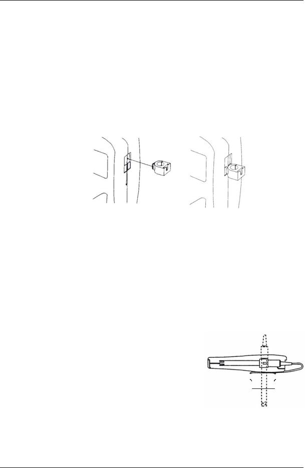
3.4Attaching the Electrode Holder to the Meter
The CON meter is designed to allow you to do a one hand operation for any measurement or calibration. For that purpose, one electrode holder is provided. They are designed for easy use and installation. Care must be taken to avoid use of excessive force in the process of attaching this component.
1.Locate the slot on the right side of the meter.
2.Gently slide the flange of the holder into the slot of the meter. Make sure the holder is secured properly into the slot.
3.The design of the electrode holder allows you to attach it to the meter in different positions.
Figure 8: Insert electrode holder
3.4.1 Inserting the electrode into the electrode holder
The holder is designed for electrodes 16 mm in diameter. Electrodes larger than 16 mm may not fit in the holder. Forcing the electrode into the opening may damage the holder or your electrode.
1.Do not use excessive force when inserting electrode into the holder.
2.Insert the conductivity electrode into the opening of the holder until the top housing of the electrode touches the top of the holder.
The electrode holder can be attached in different |
|
|
|
||
|
|
|
|||
positions for greater flexibility in measurement and |
|
|
|
||
storage purposes. |
|
|
|
||
1. |
Slide the electrode holder out from the slot of |
|
|
|
|
|
|
|
|||
|
the meter. |
Figure 9: One hand |
|||
2. |
Reorient its position into appropriate orientation |
||||
operation |
|||||
before putting back into the slot of the meter
8

Instruction Manual |
CON 11/110 |
3.5Connecting the AC/DC Adapter
Besides using the 4 “AAA” alkaline batteries as the power source, the CON 11/110 meter can also operate from the power mains using the AC/DC power adapter either at 120/220 VAC (sold separately) This is extremely useful if you have an AC power source available ( e.g. laboratory)
Please ensure that the meter and the power source of the adapter are switched off before plugging in as a safety precaution that should be adhered to safeguard your meter.
1.Switch off the meter and power sources.
2.Select the correct AC/DC Adapter either at 120/220 VAC which matches your input mains voltage.
3.Select the correct output voltage of the AC/DC adapter. (Output Voltage: 9 to
15 V DC, Current: >=50 mA).
4.Gently insert the power adapter D.C. jack into the meter power socket.
5.Switch on the power source of the adapter followed by the meter.
3.6Connecting the RS232C Cable (Only for CON 110)
The CON 110 meter provides an RS232C output for you to transmit your readings either to a printer or a computer via a cable. This is useful in instances where the meter is used for continuous monitoring of a certain process or experiment. Data output to the printer or the computer can be then evaluated.
The output data is in the ASCII format. This format allows the data to be imported by a variety of software that reads ASCII data (e.g. Microsoft’s Excel, Lotus, Quattro-pro etc.). A complimentary Data Acquisition Software (DAS) is provided and it captures data transmitted into an ASCII file for later use.
1.Gently detach the printer port cover located at the bottom end of the meter.
2.Plug the RS232C male connector into the RS232C port of the meter ensuring the correct orientation.
3.Secure the RS232C connector by fastening the two screws at the side of the male RS232C connector.
Figure 10: Location of RS232C
9

Instruction Manual |
CON 11/110 |
3.6.1 RS232C Configuration
The CON 110 meter has a 9 pin female RS232C connector with the following pin out.
PIN NO. |
DESCRIPTION |
1 |
- |
2 |
Transmit Data |
3 |
- |
4 |
- |
5 |
CTS (Clear to Send) |
6 |
- |
7 |
GND (Ground) |
8 |
- |
9 |
- |
A one to one connection can be made with a 9 pin RS232C port of the computer.
5 |
4 |
3 |
2 |
1 |
9 |
8 |
7 |
6 |
In case CON 110 meter’s output has to be sent to a 25 pin RS232C connector, the following cable configuration may be used:
CON 110 |
25 pin connector |
2 (TxD) |
(RxD) 3 |
5 (CTS) |
(RTS) 4 |
7 (GND) |
(GND) 7 |
10

Instruction Manual |
CON 11/110 |
4 CALIBRATION
4.1Important Information on Meter Calibration
Your meter has five measuring ranges. You have an option of calibrating your meter in a single point calibration for all the five ranges or for better accuracy; you can calibrate one point in each of the measuring ranges (up to five points). This selection of single point calibration and multi point calibration can be set in the SETUP menu
Program P9.2. See page 52 .
The following table lists the corresponding conductivity and TDS ranges. For either the single or multi point calibration, you should calibrate using a solution that falls between the values in the “recommended calibration solution range” column.
Conductivity Range |
Recommended |
|
Calibration |
|
Solution Range |
0 to 19.99 µS/cm, |
6.00 to 17.00 µS |
20.0 to 199.9µS/cm, |
60.0 to 170.0 µS |
200 to 1999 µS/cm; |
600 to 1700 µS |
2.00 to 19.99 mS/cm, |
6.00 to 17.00 mS |
20.0 to 199.9 mS/cm |
60.0 to 170.0 mS |
TDS Range |
Recommended |
|
Calibration Solution |
|
Range |
0.00 to 9.99 ppm |
3.00 to 8.50 ppm |
10.0 to 99.9 ppm |
30.0 to 85.0 ppm |
100 to 999 ppm; |
300 to 850 ppn |
1.00 to 9.99 ppt |
3.00 to 8.50 ppt |
10.0 to 99.9 ppt |
30.0 to 170.0 ppt |
Table 1: Recommended Calibration Solution Range in correspond to Conductivity / TDS
In single point calibration, when you recalibrate your meter, the old calibration will be replaced by the new one even if the new calibration is done in a different range from the old calibration. For example, if you have previously calibrated your conductivity meter at 1413 µS in 0 to 2000 µS range, and you recalibrate at 12.88 mS in 0 to
20.00 mS range, the new calibration will override the previous calibration in 0 to 2000 uS range.
In the case of multi point calibration, when you recalibrate your meter, old calibrations are replaced only on a range basis. For example, if you previously calibrated your conductivity meter at 1413 µS in 0 to 2000 µS range and you recalibrate at 1500 µS
(also in 0 to 2000 µS range), the meter will replace only the old calibration data (1413 µS) in that range. The meter will retain all calibration data in other ranges.
To completely recalibrate your meter, or when you use a replacement electrode, it is best to clear all calibration data. See page 45 for more information on calibration data clearance.
11

Instruction Manual |
CON 11/110 |
4.2Preparing the Meter for Calibration
Before starting calibration, make sure you are in the correct measurement mode.
For best results, select a standard value close to the sample value you are measuring. Alternatively use a calibration solution value that is approximately 2/3 the full-scale value of the measurement range you plan to use. For example, in the 0 to
2000 µS conductivity range, use a 1413 µS solution for calibration.
Perform calibration for all measurement ranges to ensure the highest accuracy throughout all measurement range. Note that CON 11/110 will not accept calibration values less than 2 µS/cm (1.0 ppm).
If you are measuring in solutions with Conductivity lower than 100 µS/cm or TDS lower than 50 ppm, calibrate the meter at least once a week to get good accuracy. If you are measuring in the mid ranges and you wash the electrode in deionised water and store it dry, calibrate the meter once a month. If you take measurements at extreme temperatures, calibrate at least once a week.
Ensure that you use new Conductivity standard solutions or sachets during calibration. Do not reuse standard solutions as it may be contaminated and affect the calibration and accuracy of measurements. Use fresh calibration solution each time you calibrate your meter. Keep solutions in a dry and cool environment if possible.
Always rinse the electrode with either tap water or rinse solution before and after each calibration/sample measurement to avoid cross-contamination.
NOTE: These meters are factory set to a temperature coefficient of 2.1% per °C. For most applications this will provide good results.
NOTE: The factory default value for normalisation temperature is 25 °C.
12
Instruction Manual |
CON 11/110 |
4.3Temperature Calibration
Your electrode features a built-in temperature sensor. The temperature sensor is
factory calibrated. Calibrate your sensor only if you suspect temperature errors may |
|
have occurred over a long period of time or if you have a |
|
replacement electrode. |
MEAS |
|
|
1.Make sure the electrode is attached to the 6-pin connector. The ATC annunciator will appear at the bottom right-hand corner of the LCD.
2.Switch the meter on. Press the CAL/MEAS key to
enter conductivity or TDS calibration mode. The CAL indicator appears above the primary display.
3.While in conductivity or TDS calibration mode, press the MODE key to enter temperature calibration mode. The primary display shows the current measured temperature reading based on the last set offset and the secondary display shows the current measured temperature reading based on factory default calibration.
1413 µS
°C
22.3 ATC
CAL
MEAS
CAL
1413 µS
1413
MODE
4.Dip the electrode into a solution of known temperature (i.e. a temperature bath). Allow time for the built-in temperature sensor to stabilise.
5.Scroll with the MI/▲ or MR/▼ keys to set the correct temperature value (i.e. the temperature of the temperature bath). You can adjust the reading in increments of 0.1 °C.
6.Once you have selected the correct temperature, press the HOLD/ENTER key to confirm. The meter will be calibrated and return to the measurement mode.
NOTES:
•To exit this program without confirming the temperature calibration value, DO NOT press HOLD/ENTER. Press CAL/MEAS instead.
•If the ATC indicator does not light up, see SETUP menu Program P1.3 to switch it on. See page 40.
•Since temperature readings affect the accuracy of conductivity / TDS measurements, it is strongly recommended to carry out a conductivity / TDS calibration after a temperature calibration is done.
CAL
22.3
22.3 °C
ATC
MI |
|
MR |
|
|
|
|
|
CAL
22.0
22.3 °C
ATC
HOLD
ENTER
MEAS
READY 1425 µS
°C
 22.0 ATC
Figure 11: Temperature
Calibration
13

Instruction Manual |
CON 11/110 |
4.4Selection of Automatic or Manual Calibration
This meter is capable of performing either automatic conductivity calibration or manual conductivity / TDS calibration.
In the automatic calibration mode, the meter automatically detects and verifies the appropriate known calibration standards solutions before accepting these particular calibration standards as one of its calibration values in a specific measurement range. This automatic calibration mode frees you from cumbersome calibration procedure.
The known calibration standards used for automatic calibration are:
Meter |
Temperature Normalisation |
Calibration Standards (Range) |
|
(tnr °C) |
|
CON |
25.0 °C |
84 µS (for 0 – 200 µS/cm) |
11/110 |
|
1413 µS (for 0 – 2000 µS/cm) |
|
|
12.88 mS (for 0.00 – 20.00 mS/cm) |
|
|
111.8 mS (for 0.0 – 200.0 mS/cm) |
|
20.0 °C |
76 µS (for 0 – 200 µS/cm) |
|
|
1278 µS (for 0 – 2000 µS/cm) |
|
|
11.67 mS (for 0.00 – 20.00 mS/cm) |
|
|
102.1 mS (for 0.0 – 200.0 mS/cm) |
|
Table 2: Conductivity Calibration Standards for Auto calibrations |
|
In the manual calibration, non-standard calibration values can be used for calibration.
You can manually input the appropriate values as your desired calibration standards in each specific range. This is useful when you have a customised calibration standard specifically unique for your application.
14

Instruction Manual |
CON 11/110 |
4.5Automatic Calibration (For Conductivity Calibration Only)
In the Automatic Calibration mode, the meter is capable of accepting either singlepoint or up to 4 points for multi-point calibration with maximum of 1 point per specific measurement range. Set up the automatic calibration mode in the SETUP menu Program P9.1 by setting to “YES”. See page 51 for the set up procedure.
The following procedure describes the method for a single point calibration to a 1413 µs conductivity calibration standard. Set the single point calibration mode to on in the
SETUP menu Program 9.2 by setting to ‘YES”. See page 52 for the single point calibration set up procedure.
1.If necessary, press the MODE key to select conductivity mode.
2.Rinse the electrode thoroughly with de-ionised water or a rinse solution, and then rinse with a small amount of calibration
standard.
3.Dip the electrode into the calibration standard. Immerse the electrode tip beyond the upper steel band. Stir the electrode gently to create a homogeneous sample. Allow time for the reading to stabilise.
4.Press CAL/MEAS to enter conductivity calibration mode. The CAL indicator will appear in the upper corner of the display. The current measured value will be displayed in the primary display whereas the value of the calibration standard will appear in the secondary display.
5.Press the HOLD/ENTER to confirm the
calibration value. The meter returns automatically to the measurement mode with the new calibrated value.
This single point calibration will apply to all the five ranges.
As for multi point calibration, set up the multi point calibration mode in the SETUP menu Program P9.2 by setting to ‘NO”.
MEAS
1356µS
°C
22.3 ATC
CAL
MEAS
CAL
1356µS
1413
HOLD
ENTER
MEAS 
READY 1413 µS
°C
22.3 ATC
Figure 12: Automatic
Conductivity Calibration
Repeat step 1 to 5 for every calibration point in each
measuring ranges using the known calibration solutions until all points have been calibrated if necessary.
15

Instruction Manual |
CON 11/110 |
|
|
IMPORTANT NOTES:
1.Meter allows a tolerance range of ±40% of its calibration standard. If the calibration standard is detected out of the tolerance range during the calibration mode, the meter will prompt by the toggling of the secondary display continuously between various calibration standard values. An error message “ERR” will be displayed for 3 seconds if you attempt to calibrate with a solution whose value is outside the tolerance range.
For instance: For 1413 µS conductivity calibration standard, 40% tolerance is from 848 µS to 1978 µS.
2.All new calibration data will over-ride existing stored calibration data for each measuring range calibrated.
3.It is important to use new conductivity calibration standards.
4.Low conductivity standard solution (less than 20 µS /cm) cannot be available easily. Such low conductivity standard will be contaminated as soon as it is exposed to the air. It is therefore for this reason automatic calibration in the first measurement range (0.00 to 20.0 µS /cm) of this meter is not possible.
16
Instruction Manual |
CON 11/110 |
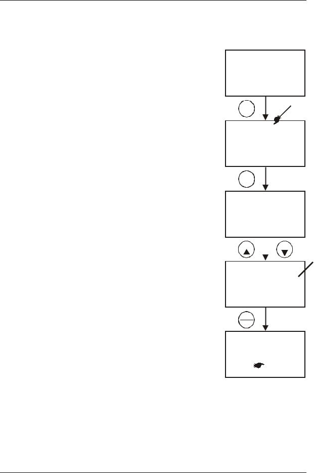
4.6Manual Calibration (For Conductivity & TDS Calibration)
In Manual Calibration mode, you can use customised Conductivity / TDS calibration standards (specific to your own application) and calibrate the meter. The following example shows the calibration sequence to 12.00 mS conductivity calibration standard. Set up the manual calibration mode in the SETUP menu Program P9.1 by setting to “NO”. See page 51.
The following procedure describes the method for a single point calibration. Set the single point calibration mode to on in the SETUP menu Program 9.2 by setting to ‘YES”. See page 52 for the single point calibration set up procedure.
1.If necessary, press the MODE key to select conductivity mode.
2.Rinse the electrode thoroughly with de-ionised water or a rinse solution, and then rinse with a small amount of calibration standard.
3.Dip the electrode into the calibration standard.
Immerse the electrode tip beyond the upper steel band (see Figure 6 in page 6). Stir the electrode gently to create a homogeneous sample. Allow time for the reading to stabilise.
4.Press CAL/MEAS key to enter conductivity calibration mode. The CAL indicator will appear in the upper corner of the display. The upper
(primary) display shows the measured value which is with respect to the last calibration while the lower (secondary) display shows the measured value with respect to the default calibration.
NOTE: To exit calibration without confirmation, press CAL/MEAS key again to go back to measurement mode.
5.Wait for the value to stabilise and press MI/▲ or
MR/▼ key and adjust the value in the upper display to the calibration standard used.
6.Press the HOLD/ENTER key to confirm. The meter returns to measurement mode with the new calibrated value.
MEAS
11.87mS
°C
22.3 ATC
CAL
MEAS
CAL
11.87mS
11.87
MI MR
CAL
12.00mS
11.87
HOLD
ENTER
MEAS 
READY 12.00mS
°C
22.3 ATC
This single point calibration will apply to all the five ranges. Figure13: Manual
Calibration
As for multi point calibration, set up the multi point calibration mode in the SETUP menu Program P9.2 by setting to ‘NO”.
Repeat step 1 to 6 for every calibration point (one in each measuring range) using the desired calibration solutions until all points have been calibrated.
17

Instruction Manual |
CON 11/110 |
4.7TDS Calibration
4.7.1 Calibrating for TDS Using Conductivity Standards & adjusting TDS factor
It is important to note that the increase in concentration of salts dissolved in solution increases the conductivity of that solution. This relationship varies from salt to salt and is roughly linear over a given range for a given salt. The TDS conversion factor is the number used by the meter to convert from conductivity to TDS.
Instead of calibrating for TDS directly using TDS calibration standard solutions, you can have TDS calibration by using the conductivity calibration method and enter the appropriate TDS conversion factor into the meter.
For more information regarding TDS Conversion Factor determination, please refer to page 73.
4.7.2 Setting the TDS Conversion Factor
The factory default setting for TDS conversion factor is 0.5.
If your solution has a different TDS factor, you can improve calibration accuracy by setting the TDS factor prior to calibration.
1.Press MODE key to select TDS mode.
2.Press Setup key to enter SETUP Menu.
3.Press the HOLD/ENTER key a few times to scroll through the sub programs until you view Program
P1.4
4.Press the HOLD/ENTER key again. The upper display shows a value and the lower display shows “tdS”.
5.Press the MI/▲ or MR/▼ keys to select your
calculated TDS conversion factor.
6.Press the HOLD/ENTER key to confirm selection and to return to the subgroup menu.
7.Press the CAL/MEAS key to return to
measurement mode.
NOTE: The set up program P1.4 for setting the TDS conversion factor is only activated when set up menu is entered while the meter is in the TDS measurement mode.
Only from TDS Measurement Mode
SETUP
SETUP
cof
p1.0
HOLD
ENTER
SETUP
ppt ppm
p1.4
HOLD
ENTER
SETUP
0.50 pptppm
MI |
|
MR |
|
|
|
|
|
SETUP
0.75ppt
ppm
Figure 14: Setting the TDS
Conversion Factor
18

Instruction Manual |
CON 11/110 |
|
|
4.7.3 Calibrating for TDS using TDS standards
After setting the correct TDS Factor, you can commence calibration in the TDS mode.
From the measurement mode,
1.If necessary, press the MODE key to select the TDS mode.
2.For the rest of the calibration process, repeat the similar step 2 to 6 as in the section of Manual Calibration on page 17, this time using the TDS calibration standards.
NOTE: You can offset the TDS reading up to ± 40% from the default setting. If your measured value differs by more than ± 40%, clean or replace electrode as needed.
19

Instruction Manual |
CON 11/110 |
5 MEASUREMENT
This meter is capable of taking measurements with automatic (ATC) or manual
(MTC) temperature compensation. Factory default is ATC on.
5.1Automatic Temperature Compensation
For automatic temperature compensation (ATC), simply attach the conductivity/TDS electrode to the meter. Ensure that the
ATC mode has been selected in the SETUP menu. The ATC indicator will light on the LCD.
NOTE: If the conductivity/TDS electrode is not properly attached to the meter or it has been damaged, the ATC indicator will blink and the temperature display will show
“Ur”.
MEAS
READY 1413 µS
°C
22.3 ATC
Figure 15: Automatic
Temperature Compensation
If the ATC indicator does not light and the temperature
display shows a reading, ATC mode may have been replaced with the manual temperature compensation mode in the meter’s SETUP menu. See page 21 Section
5.2 on Manual Temperature Compensation.
Automatic Temperature Compensation mode can be restored by setting the SETUP Menu Program P1.3 to YES.
20
 Loading...