


CON 400
Technolo
g
y
M
ade
E
a
s
y
.
.
.
Instruction Manual
CON 400 and CON 410
Waterproof Hand-held Conductivity/TDS Meter
68X248904
Rev 3 01/04

Preface
This manual serves to explain the use of the Waterproof CON 400/410 hand-held meters. It
functions in two ways, firstly as a step by step guide to help you to operate the meter.
Secondly, it serves as a handy reference guide. It is written to cover as many anticipated
applications of the Waterproof CON 400/410 meters as possible. If there are doubts in the
use of the meter, please do not hesitate to contact the nearest Authorised Distributor.
Eutech Instruments/ Oakton Instruments cannot accept any responsibility for damage or
malfunction to the meter caused by improper use of the instrument.
The information presented in this manual is subject to change without notice as improvements
are made, and does not represent a commitment on the part of Eutech Instruments Pte Lt d/
Oakton Instruments.
Copyright © 1999
Eutech Instruments Pte Ltd/ Oakton Instruments
All rights reserved.
Rev 3, 01/04

TABLE OF CONTENTS
1 INTRODUCTION ..............................................................................................1
2 DISPLAY AND KEYPAD FUNCTIONS.............................................................2
2.1 DISPLAY ....................................................................................................................2
2.2 KEYPAD.....................................................................................................................3
3 PREPARATION................................................................................................4
3.1 INSERTING THE BATTERIES.........................................................................................4
3.2 CONDUCTIVITY ELECTRODE INFORMATION ..................................................................5
3.3 CONNECTING THE PROBE TO THE METER.....................................................................6
4 CALIBRATION..................................................................................................7
4.1 IMPORTANT INFORMATION ON METER CALIBRATION.....................................................7
4.2 PREPARING THE METER FOR CALIBRATION.................................................................. 8
4.3 TEMPERATURE CALIBRATION......................................................................................9
4.4 CONDUCTIVITY CALIBRATION .................................................................................... 10
4.5 TDS CALIBRATION...................................................................................................12
4.5.1 Calibrating for TDS directly ........................................................................... 12
4.5.2 Calibration with Conductivity Standard and TDS factor................................ 13
5 MEASUREMENT............................................................................................15
5.1 AUTOMATIC TEMPERATURE COMPENSATION .............................................................15
5.2 MANUAL TEMPERATURE COMPENSATION ..................................................................16
5.2.1 Selecting Manual Temperature Compensation.............................................16
5.2.2 Setting a manual temperature compensation value......................................17
5.3 TAKING MEASUREMENTS..........................................................................................18
5.4 USING MANUAL RANGING FUNCTION.........................................................................19
5.5 HOLD FUNCTION.....................................................................................................20
6 MEMORY AND DATA INPUT FUNCTIONS...................................................21
6.1 MEMORY INPUT........................................................................................................ 21
6.2 MEMORY RECALL.....................................................................................................22
7 ADVANCED SETUP FUNCTIONS.................................................................23
7.1 ADVANCED SETUP MODE OVERVIEW.......................................................................25
7.2 P 1.0: MEMORY CLEAR (CLR).................................................................................. 27
7.3 P2.0: VIEWING CALIBRATION DATA ............................................................................28
7.4 P3.0: VIEWING PROBE DATA .....................................................................................29
7.5 P4.0: UNIT CONFIGURATION .....................................................................................30
7.5.1 P4.1: READY indicator and auto endpoint function ......................................30
7.5.2 P4.2 Selecting
°
C or
°
F................................................................................. 31
7.5.3 P4.3 Selecting Automatic or Manual Temperature Compensation.............. 32
7.5.4 P4.4 Setting the TDS factor .........................................................................33
7.6 P5.0 TEMPERATURE................................................................................................34
7.6.1 P5.1 Adjusting the temperature coefficient ..................................................34
7.6.2 P5.2 Adjusting the normalization temperature............................................. 35
7.7 P6.0 SELECTING THE CELL CONSTANT ......................................................................36
7.8 P7.0: SETTING THE REAL-TIME CLOCK.......................................................................37
7.9 P8.0: RESETTING TO FACTORY DEFAULT SETTINGS....................................................39

8 PROBE CARE AND MAINTENANCE.............................................................40
9 TROUBLE SHOOTING GUIDE.......................................................................41
10 ERROR MESSAGES..................................................................................42
11 SPECIFICATIONS......................................................................................43
12 ACCESSORIES..........................................................................................44
13 ADDENDUM 1: CALIBRATION TIPS ........................................................45
14 ADDENDUM 2: CALCULATING TDS CONVERSION FACTORS..............46
14.1 “PREPARING YOUR OWN TDS CALIBRATION STANDARDS”........................................... 46
15 ADDENDUM 3: CALCULATING TEMPERATURE COEFFICIENTS..........47
16 ADDENDUM 4: METER FACTORY DEFAULT SETTINGS .......................48
17 WARRANTY ...............................................................................................49
18 RETURN OF ITEMS...................................................................................50
Instruction Manual CON 400/410
- 1 -
1 INTRODUCTION
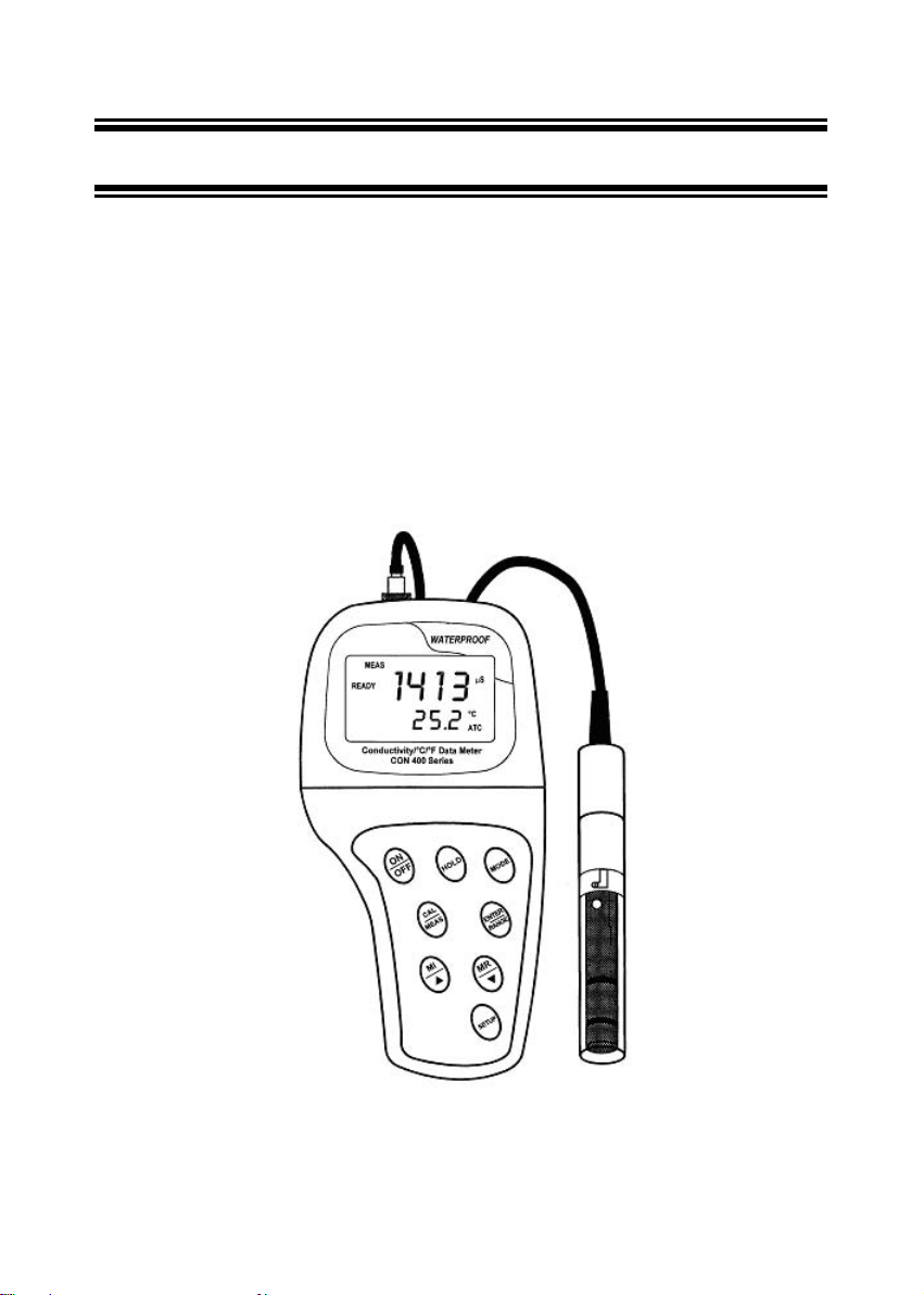
Thank you for selecting the CON 400/410 waterproof portable meter. This meter is a
microprocessor-based instrument that is designed to be user-friendly and allow one-hand
operation. It has a built-in real time clock, expanded memory, and many other user-friendl y
features, all of which are accessible through the membrane keypad. It is completely
WATERPROOF --- and it FLOATS! You have one of the following models:
• CON 400 meter: reads conductivity and temperature.
• CON 410 meter: reads conductivity, TDS and temperature.
Your meter includes 4 ‘AAA’ batteries and a conductivity electrode (cell constant K = 1.0) with
built-in temperature sensor. Please read this manual thoroughly before operating your meter.
Instruction Manual CON 400/410
- 2 -
2 DISPLAY AND KEYPAD FUNCTIONS
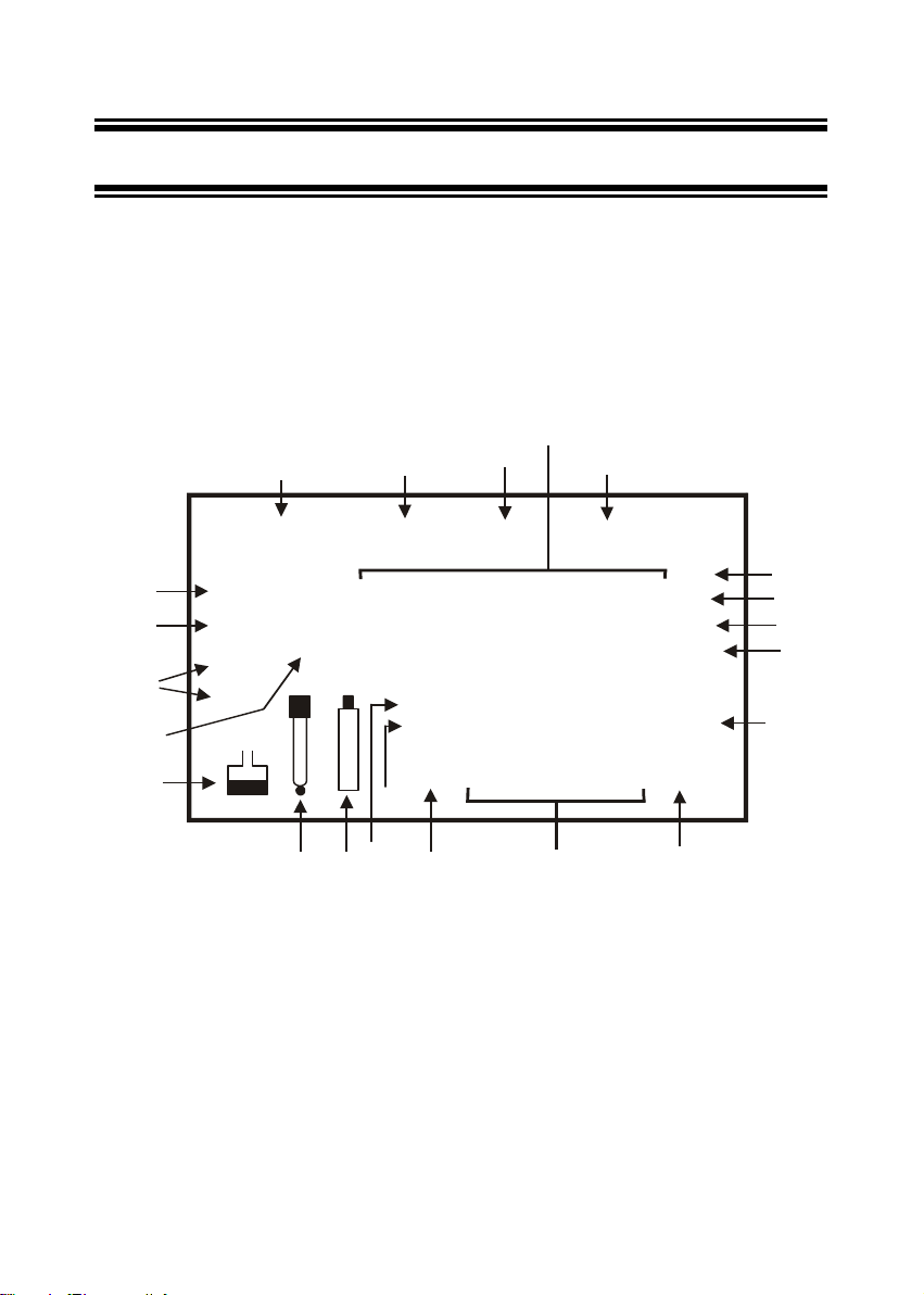
2.1 Display
The LCD has a primary and secondary display.
• The primary display shows the measured conductivity or TDS reading.
• The secondary display shows the measured temperature.
The display also shows error messages, keypad functions and program functions.
See Figure 1.
SETUP MEAS CAL MEM
Primary Display
Secondary Display
MEM
ERR
AM PM
ATC
°C °F
READY
HOLD
ON
OFF
-8.8.8.8
-1.8.8.8
12
3
4
5
6
7
8
9
1011
12
131415
16
17
18
19
20
mS
ppt
ppm
µ
S
K =
Figure 1: Full LCD Screen
1. SETup mode indicator 8. parts per million indicator (CON
410 meter only)
15. Probe indicator
2. MEASurement mode indicator 9. Temperature indicator 16. Calibration solution indicator
3. CALibration indicator 10. Automatic Temperature
Compensation indicator
17. Cell constant indicator
4. MEMory recall mode indicator 11. Clock indicator 18. ON / OFF indicator
5. millisiemens indicator 12. ERRor indicator 19. HOLD indicator
6. microsiemens indicator 13. MEMory location indicator 20. READY indicator
7. parts per thousand indicator
(CON 410 meter only)
14. Low battery indicator
Instruction Manual CON 400/410
- 3 -
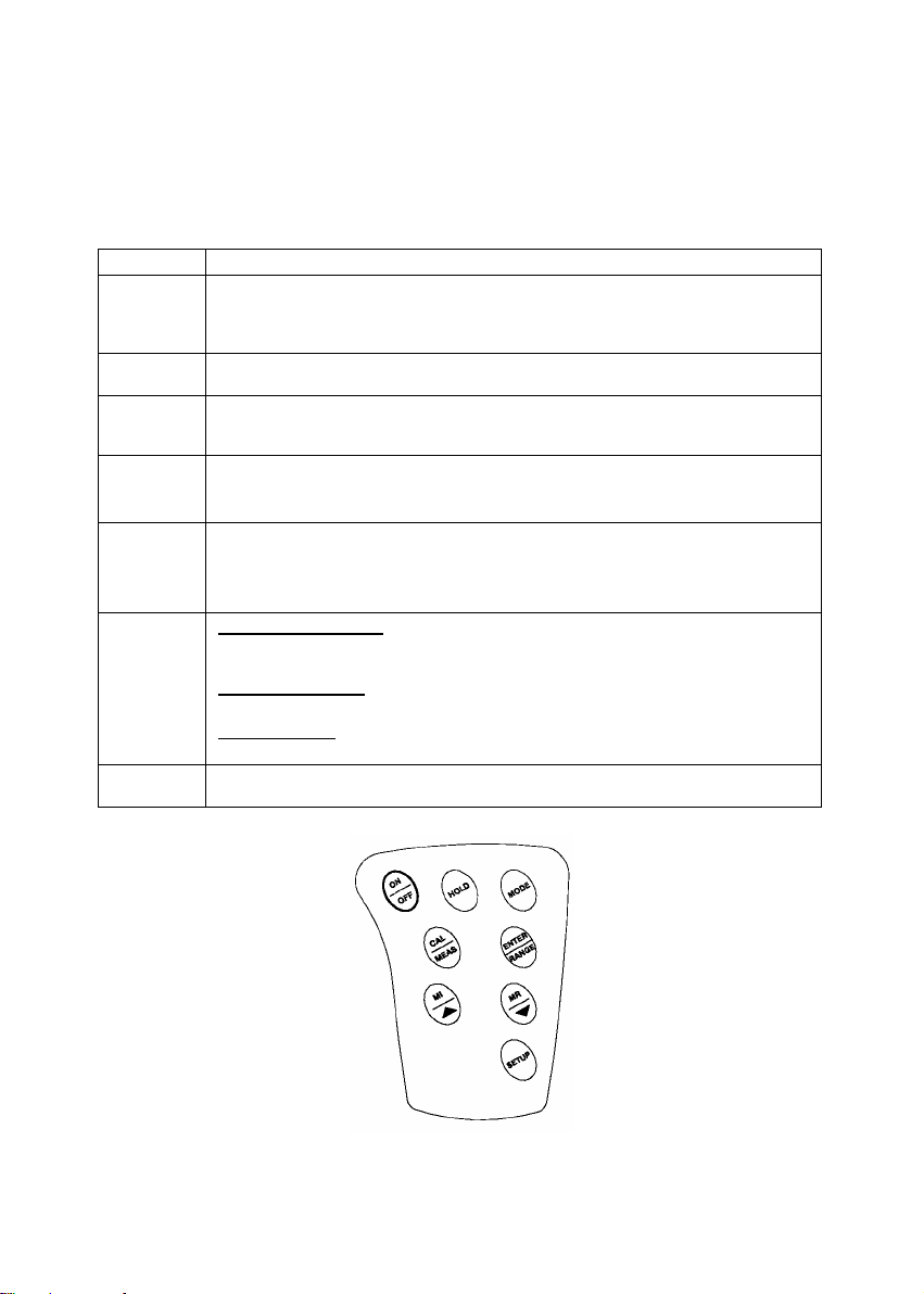
2.2 Keypad
The large membrane keypad makes the instrument easy to use. Each button, when pressed,
has a corresponding graphic indicator on the LCD. See Figure 2. Some buttons have several
functions depending on its mode of operation.
Key Function
ON/OFF Powers on and shuts off the meter. When you switch on the meter, the meter starts up
in the mode that you last switched off from. For example, if you shut the meter off in
TDS measurement mode (only in CON 410 meter), the meter will be in TDS
measurement mode when you switch the meter on.
HOLD Freezes th e m easured reading. To activate, press HOLD while in measurement mode.
To release, press HOLD again.
MODE Selects the measurement parameter.
~ CON 400 meter: Toggles between conductivity and time.
~ CON 410 meter: Toggles between conductivity, TDS and time.
CAL/MEAS Toggles between Calibration and Measurement mode.
NOTE: Temperature calibration is available from conductivity calibration mode; see
page 9 for directions.
ENTER /
RANGE
ENTER function: Press to confirm values in Calibration mode and to confirm selections
in SETUP mode.
RANGE function: Press to enter manual ranging function.
The MEAS indicator blinks while in manual ranging function.
MI/S and
MR/T
In Measurement mode:
Press MI/S (memory input) to store values with its corresponding temperature values in
the memory. Press MR/T (memory recall) to retrieve data from memory.
In Calibration mode:
Press to scroll through calibration values.
In SETUP mode:
Press to scroll through the setup subgroup programmes.
SETUP Takes you into the SETUP mode. This mode lets you customise meter preference and
defaults, and view calibration, electrode offset data and select cell constant.
Figure 2 - Keypad
Instruction Manual CON 400/410
- 4 -
3 PREPARATION
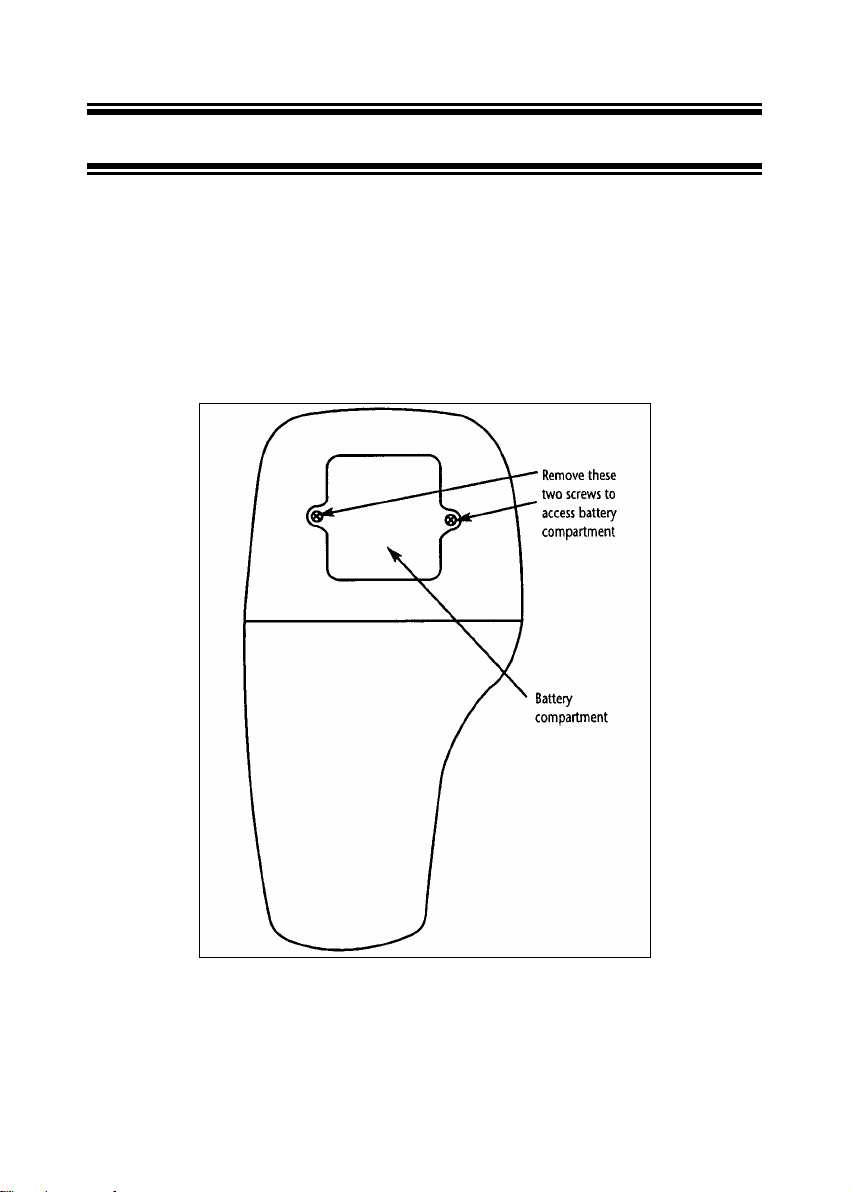
3.1 Inse rting the Batteries
Four AAA batteries are included with your meter.
1. Use a Philips screwdriver to remove the two screws holding the battery cover. See Figure
3 below.
2. Remove battery cover to expose batteries.
3. Insert batteries. Follow the diagram inside the cover for correct polarity.
4. Replace the battery cover into its original position using the two screws removed earlier.
Figure 3 - Back panel of meter showing meter compartment
Instruction Manual CON 400/410
- 5 -
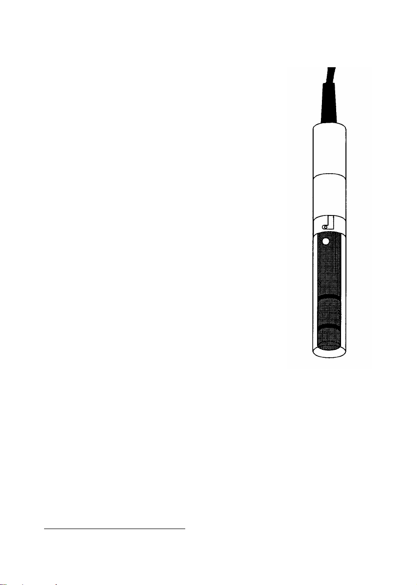
3.2 Conducti vity Electrode Information
The CON400/410 meter uses a conductivity / TDS cell with a
sturdy 6-pin connector.
Your meter includes a conductivity probe (Part No: EC-
CONSEN91W / 35608-50) Ultem / Stainless Steel cells with a cell
constant of K = 1.0. This conductivity / TDS cell features a built-in
temperature sensor for Automatic Temperature Compensation
(ATC). It has a specially designed housing that provides fast
temperature response and reduces air bubble entrapment, which
makes it easy to obtain accurate, stable readings.
Wetted parts include:
1. Polyetherimide (Ultem™)
2. Polybutylterphalate (Valox™)
1
3. Stainless Steel (SS 304)
NOTE: We recommend that you do not submerge the probe above
the protective yellow cap for prolonged periods. The protective
yellow cap can be removed for cleaning, but must be attached at
all times during calibration or measurment.
See Section 8 on page 40 for “Probe Care and Maintenance”
information.
1
Valox and Ultem are trademark names of General Electric Co.
Figure 4 - Conductivity probe
(EC-CONSEN91W/ 35608-50)
Instruction Manual CON 400/410
- 6 -
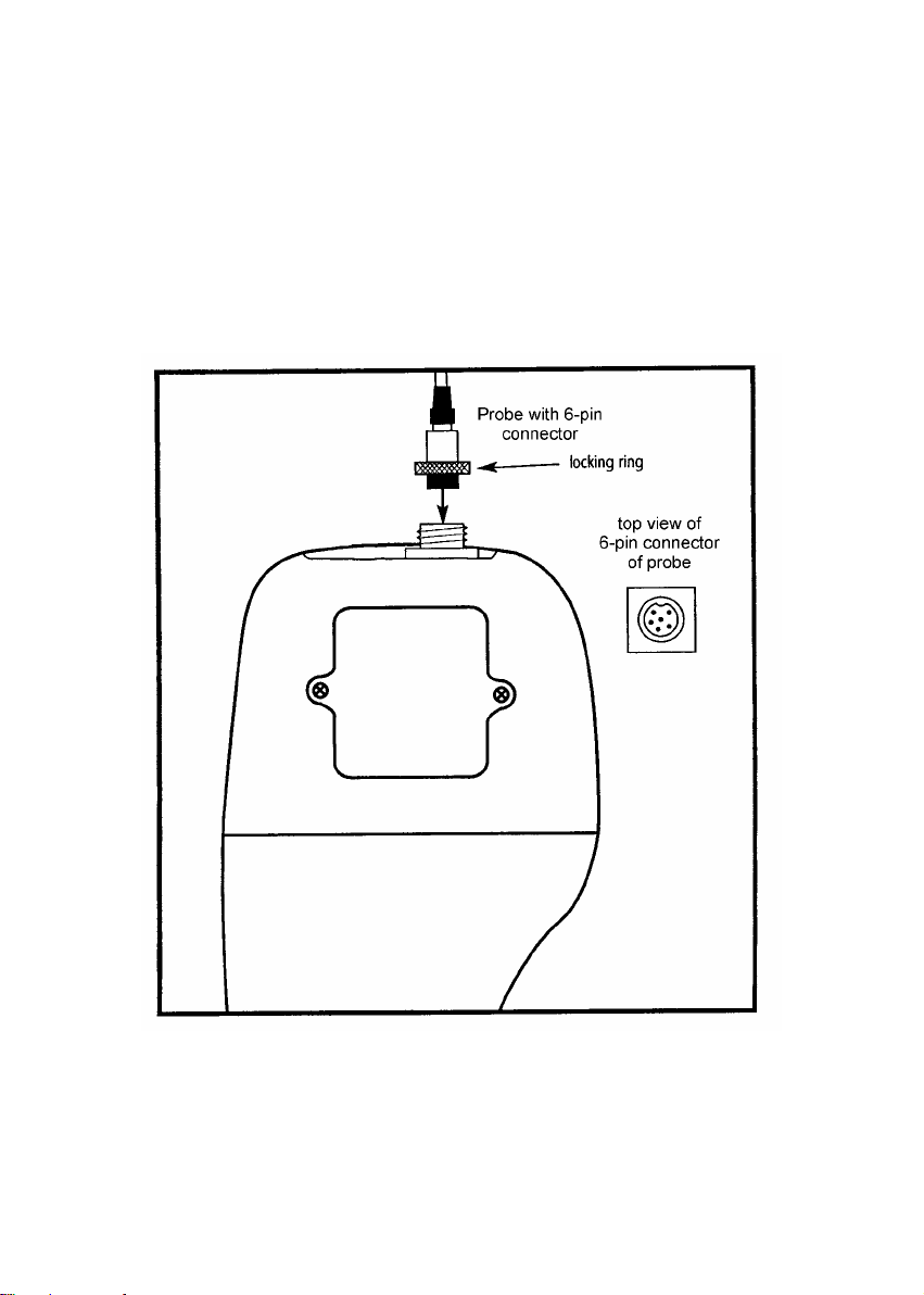
3.3 Connecting the p robe to the meter
1. Line up the notch and 6 pins on the meter with the holes in the 6-pin connector. Push
down and turn the locking ring clockwise to lock into place. See figure below.
2. To remove probe, turn the locking ring counterclockwise on the probe connector. Pull
probe away from the meter.
CAUTION: Do not pull on the probe cord or the probe wires might disconnect.
NOTE: Keep connectors clean. Do not touch connector with soiled hands.
Figure 5 - Connection for Conductivity probe (6-pin connector)
Instruction Manual CON 400/410
- 7 -
4 CALIBRATION
4.1 Imp ortant Information on Meter Calibrat ion
Your meter has five measuring ranges. You can calibrate one point in each of the measuring
ranges (up to five points). If you are measuring values in more than one range, make sure to
calibrate each of the ranges you are measuring.
To view current calibration points, see SETUP section Program 2.0 on page 28.
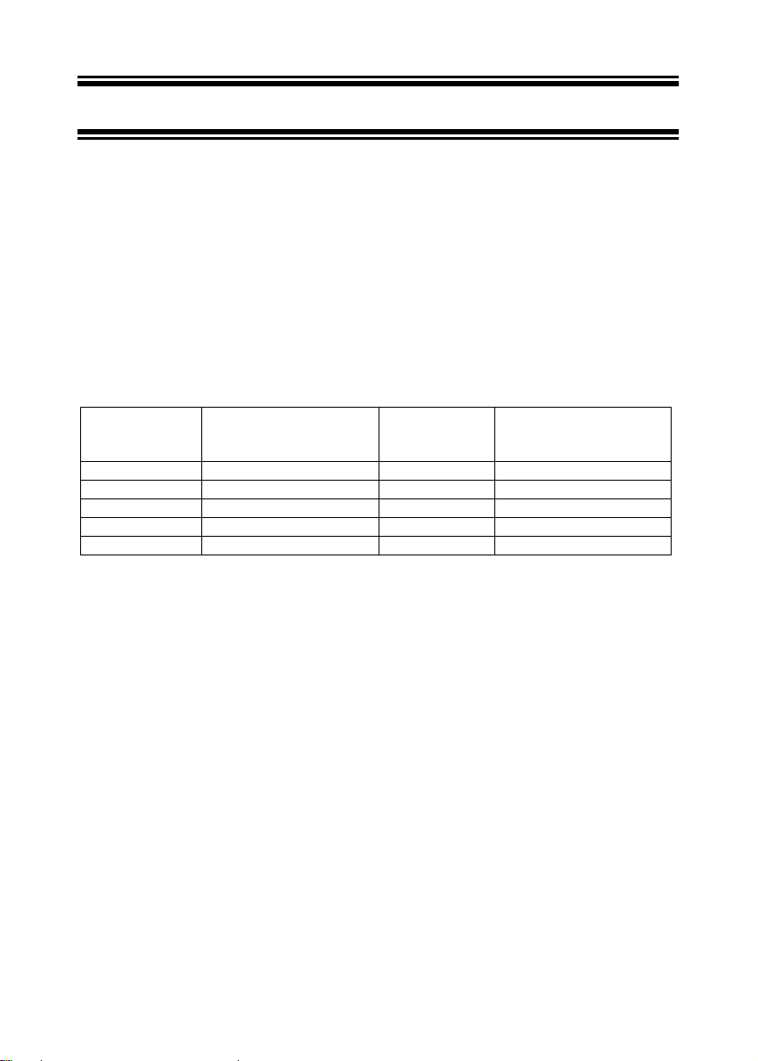
The following table lists the corresponding conductivity and TDS ranges. You should calibrate
each range using a solution that falls between the values in the “recommended calibration
solution range” column.
Conductivity
Measuring
Range
Recommended
Calibration Solution
Range
TDS Measuring
Range
Recommended
Calibration Solution
Range
0.00 Æ 19.99 µS 6.00 to 17.00 µS 0.00 Æ 9.99 ppm 3.00 to 8.50 ppm
0.0 Æ 199.9 µS 60.0 to 170.0 µS 10.0 Æ 99.9 ppm 30.0 to 85.0 ppm
0 Æ 1999 µS 600 to 1700 µS 100 Æ 999 ppm 300 to 850 ppm
0.00 Æ 19.99 mS 6.00 to 17.00 mS 1.00 Æ 9.99 ppt 3.00 to 8.50 ppt
0.0 Æ 199.9 mS 60.0 to 170.0 mS 10.0 Æ 200 ppt 30.0 to 170 ppt
When you recalibrate your meter, old calibrations are replaced on a range by range basis. For
example, if you previously calibrated your conductivity meter at 1413 µS in the 0 to 1999 µS
range and you recalibrate at 1500 µS (also in the 0 to 1999 µS range), the meter will replace
the old calibration data (1413 µS) in that range. The meter will retain all calibration data in
other ranges.
To completely recalibrate your meter, or when you use a replacement probe, it is best to clear
all calibration data in memory. To erase all the old conductivity and TDS calibration data
completely from memory, see SETUP section Program 8.0 on page 39.
For information on how to calibrate your meter:
• See section 4.3 for Temperature Calibration.
• See section 4.4 for Conductivity
• See section 4.5 for TDS Calibration (CON 410 meter only).
• See Addendum 1 for more calibration tips.

Instruction Manual CON 400/410
- 8 -
4.2 Prep aring the Meter for Calib ration
Before starting calibration, make sure you are in the correct measurement mode. When you
switch on the meter, the meter begins with the units you shut it off in.
For best results, select a standard value close to the sample value you are measuring.
Alternatively use a calibration solution value that is approximately 2/3 the full-scale value of
the measurement range you plan to use. For example, in the 0 to 1999 µS conductivity range,
use a 1413 µS solution for calibration.
Do not reuse calibration solutions after calibration. Contaminants in the solution can affect the
calibration, and eventually the accuracy of the measurements. Use fresh calibration solution
each time you calibrate your meter.
NOTE: Your meter is factory set to a temperature coefficient of 2.1% per °C. For most
applications this will provide good results. See Program P5.1 on page 34 to set the
temperature coefficient to different value. See Addendum 3, “Calculating Temperature
Coefficients” to determine the appropriate temperature coefficient for your solution.
NOTE: The factory default value for normalization temperature is 25 °C. If you need to
normalize to a value other than 25 °C, see Program P5.2 on page 35.
Instruction Manual CON 400/410
- 9 -
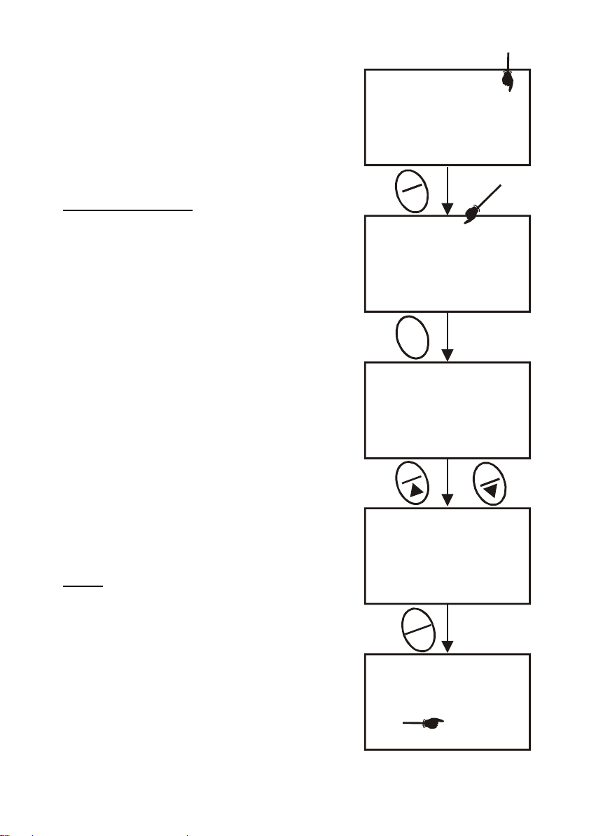
4.3 Te mperature Calibration
Your probe features a built-in temperature sensor. The
temperature sensor is factory calibrated. Calibrate your
sensor only if you suspect temperature errors that may
have occurred over a long period of time or if you have a
replacement probe.
Temperature Calibration
1. Make sure the cell is attached to the 6-pin connector.
The ATC annunciator will appear at the right-hand
side of the LCD*.
2. Switch the meter on. Press the MODE key to select
conductivity or TDS mode.
3. Press the CAL/MEAS key to enter conductivity or
TDS calibration mode. The CAL indicator appears
above the primary display.
4. While in conductivity or TDS calibration mode, press
the MODE key to enter temperature calibration
mode. The primary display shows the current
temperature reading and the secondary display
shows the factory default temperature value.
5. Dip the cell into a solution of known temperature (i.e.
A temperature bath). Allow time for the built-in
temperature sensor to stabilise.
6. Scroll with the MI/S or MR/T keys to set the correct
temperature value (i.e. the temperature of the
temperature bath). You can adjust the reading in
increments of 0.1 °C.
7. Once you have selected the correct temperature,
press the ENTER key.
* If the ATC indicator does not light up, see Program P4.3
to switch it on.
NOTES:
• You can offset the temperature reading up to ±5°C from
the original reading (default reading).
• To exit this program without confirming the temperature
calibration value, DO NOT press ENTER. Press
CAL/MEAS instead.
• If the ATC indicator does not light, see Prog ram P4.3,
on page 32 to switch it on.
• Since temperature readings affect the accuracy of the
conductivity/TDS measurements, it is strongly
recommended to carry out a conductivity/TDS
calibration after a temperature calibrati on is done.
Figure 10 - Temperature
Calibration
MEAS
1413
1413
ATC
°C
22.3
ATC
°C
22.3
MEAS
ATC
°C
22.0
CAL
CAL
ATC
°C
22.3
22.3
ATC
°C
22.0
22.3
CAL
C
A
L
M
E
A
S
READY
M
R
M
I
M
O
D
E
µ
S
µ
S
1425
µ
S
E
N
T
E
R
R
A
N
G
E
Instruction Manual CON 400/410
- 10 -
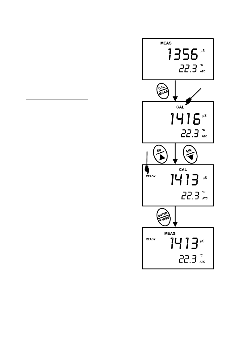
4.4 Conductivity Calibration
The CON 400 and CON 410 meters are capable of up
to 5-point conductivity calibration at one point per
conductivity range (0.00 - 19.99 µS; 0.0 - 199.9 µS; 0 -
1999 µS; 0.00 - 19.99 mS; 0.0 - 199.9 mS).
All new calibration data will over-ride existing stored
calibration data for each measuring range calibrated.
Calibrating for Conductivity:
1. If necessary, press the MODE key to select
conductivity mode.
2. Rinse the probe thoroughly with de-ionized (DI)
water or a rinse solution, then rinse with a small
amount of calibration standard.
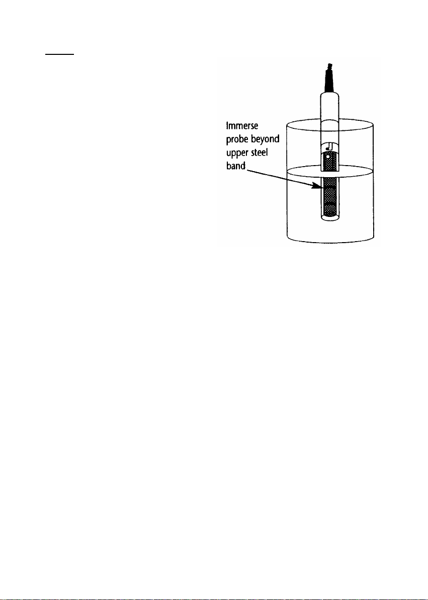
3. With the yellow probe guard attached, dip the
probe into the calibration standard. Immerse the
probe tip beyond the upper steel band. Stir the
probe gently to create a homogeneous sample.
Allow time for the reading to stabilizse.
See Figure 7.
4. Press CAL/MEAS to enter conductivity
calibration mode. The CAL indicator will appear
in the upper right corner of the display.
5. Press the MI/S or MR/T key to change the
value on the primary display to match the value
of the calibration standard referenced to your
normalisation temperature (usually 25°C).
6. Press ENTER to confirm calibration value. The
meter returns to the MEAS (measurement) mode.
7. Repeat steps 1 to 6 for other measuring ranges.
See figure 6.
Figure 6 - Conductivity Calibration
Instruction Manual CON 400/410
- 11 -
NOTES:
When entering calibration mode, the meter
displays the factory default value. If the meter
was previously calibrated, the display may
seem to “jump” to the factory default value
when switching from measurement to
calibration mode. This is expected.
To exit from Conductivity calibration
mode without confirming calibration, DO
NOT press the ENTER key in step 6. Press
CAL/MEAS instead. This will retain the
meter’s old calibration data in the measuring
range of the calibration.
You can offset the conductivity reading up to
±40% from factory default value. If your
measured value differs by more than ±40%,
clean or replace probe if needed.
The minimum offset reading allowable is
limited to 10% of full scale reading of the
range you are working in. The maximum offset reading allowed is the range full scale reading
Eutech Instruments/ Oakton Instruments offers a wide selection of high-quality calibration
standards. See page 44 for more information.
Figure 7 - Proper Immersion of
the conductivity probe
Instruction Manual CON 400/410
- 12 -
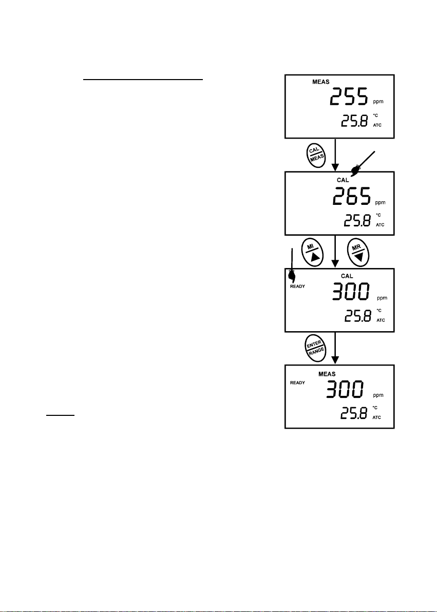
4.5 TDS Calibration
4.5.1 Calibrating for TDS directly
For CON 410 meter only
The factory default setting for the TDS conversion factor is
0.50. If your solution has a different TDS factor, you can
improve calibration accuracy by setting the TDS factor prior to
calibration. See page 33 for directions.
1. If necessary, press the MODE key to select TDS mode.
2. Rinse the probe thoroughly with DI water or a rinse
solution, then rinse with a small amount of calibration
standard.
3. With the yellow probe guard attached, dip the probe into
the calibration standard. Immerse the probe tip beyond
the upper steel band. Stir the probe gently to create a
homogeneous sample. Allow time for the reading to
stabilise.
4. Press CAL/MEAS to enter TDS calibration mode. The
CAL indicator will appear in the upper right corner of the
display.
5. Press the MI/S or MR/T to change the value on the
primary display to match the value of the calibration
standard referenced to your normalisation temperature
(usually 25°C).
6. Press ENTER to confirm the calibration value. The meter
returns to the MEAS (measurement) mode.
7. Repeat steps 1 to 6 for other measuring ranges.
NOTES
To exit from TDS Calibration mode without confirming
calibration, DO NOT press the ENTER key in step 6. Press
CAL/MEAS instead. This will retain the meter’s old calibration
data in the measuring range of the calibration.
You can offset the TDS reading up to ±40% from the default
setting. If your measured value differs by more than ±40%,
clean or replace probe as needed.
The minimum offset reading allowable is limited to 10% of full scale reading of the range you
are working in. The maximum offset reading allowed is the range full scale reading
Eutech Instruments/ Oakton Instruments offer a wide selection of high-quality calibration
standards. See page 44 for more information.
Figure 8 - TDS Calibration

Instruction Manual CON 400/410
- 13 -
4.5.2 Calibration with Conductivity Standard and TDS factor
For CON 410 meter only
The concentration of salts dissolved in solution increases the conductivity of that solution. This
relationship varies from salt to salt and is roughly linear over a given range for a given salt.
The TDS conversion factor is the number used by the meter to convert f rom conductivity to
TDS.
Instead of calibrating for TDS directly (described in Section 4.5.1), you can calibrate the CON
410 meter by:
1. calibrating to conductivity standards (as described on pages 10 to 11) and then
2. entering the appropriate TDS conversion factor into the meter.
To determine the conductivity to TDS conversion factor for your solution:
• Addendum 2 explains the formula to calculate the conductivity-to-TDS
conversion factor.
Enter the TDS conversion factor into your meter as described under Section 7.5.4, in P4.4
Setting the TDS Factor on page 33.
 Loading...