


Instruction Manual
pH 1000/ pH 2500
Bench pH/Ion Meter
68X090800 Rev. 5 07/03
Technology Made Easy ...
Instruction Manual |
pH 1000/ 2500 |
Instruction Manual |
pH 1000/ 2500 |
Preface
Thank you for choosing the pH 1000/ 2500 bench meter series.
This manual serves to explain the use of the pH 1000/ 2500 Bench meter. The manual functions in two ways, firstly as a step-by-step operational guide to help you familiarize with the meter’s features and functions. Secondly, it serves as a handy reference guide.
This instruction manual is written to cover as many anticipated applications and uses of the pH 1000/ 2500 bench meter as possible. If there are doubts in the use of the meter, please do not hesitate to contact the nearest Authorized Distributors.
Eutech Instruments/ Oakton Instruments cannot accept any responsibility for damage or malfunction to the meter caused by improper use of the instrument.
The information presented in this manual is subject to change without notice as improvements are made, and does not represent a commitment on the part of Eutech Instruments Pte Ltd/ Oakton Instruments.
Note: Eutech Instruments Pte Ltd/ Oakton Instruments reserves the right to make improvements in design, construction, and appearance of our products without notice.
Copyright © 1998 All rights reserved.
Eutech Instruments Pte Ltd
Oakton Instruments
Rev. 5 07/03
Instruction Manual |
pH 1000/ 2500 |
|
|
|
TABLE OF CONTENTS |
|
1 |
INTRODUCTION |
1 |
||
2 |
METER INFORMATION |
1 |
||
|
2.1 |
Meter Parts |
1 |
|
|
2.2 |
Customized LCD |
1 |
|
|
2.3 |
Slide Out Card |
1 |
|
|
2.4 |
Rear Instrument Panel |
1 |
|
|
2.5 |
AC/DC-Adapter |
2 |
|
|
2.6 |
Electrode |
2 |
|
3 |
KEYPAD FUNCTIONS |
3 |
||
|
3.1 |
Primary & Secondary Functions of Keypad |
3 |
|
4 STARTING UP THE METER |
6 |
|||
|
4.1 |
Connecting the Sensor Electrode |
6 |
|
|
4.2 |
Connecting the Temperature Probe |
6 |
|
|
4.3 |
Connecting the AC/DC Adapter |
6 |
|
|
4.4 |
Connecting the Chart Recorder |
6 |
|
|
4.5 |
Connecting RS232C Cable |
6 |
|
5 TURNING THE METER ON AND OFF |
7 |
|||
6 |
CALIBRATION |
8 |
||
|
6.1 |
pH Calibration (With ATC) |
8 |
|
|
6.1.1 1 Point pH Calibration |
8 |
||
|
6.1.2 |
Option 1 - Standard Buffers |
8 |
|
|
6.1.3 |
Option 2 - Non-Standard Buffers |
9 |
|
|
6.2 |
Multi-Point pH Calibration (Up to 5 Points) |
9 |
|
|
6.3 |
Special Topic: CAL EDIT (for Custom/Non-Standard Buffers) |
10 |
|
|
6.4 |
pH Calibration (without ATC) |
10 |
|
|
6.5 |
Relative mV Calibration |
11 |
|
|
6.6 |
Ion Calibration (for pH 2500 only) |
12 |
|
|
6.7 |
Temperature Calibration |
13 |
|
7 MEASUREMENT: READY, CONTINUOUS AND HOLD |
14 |
|||
|
7.1 |
Measurement in the READY Mode |
14 |
|
|
7.2 |
Measuring in the Continuous Mode |
14 |
|
|
7.3 |
HOLD Function |
14 |
|
|
7.3.1 Holding and Releasing a Measured Value |
14 |
||
|
7.4 |
Measuring pH |
15 |
|
|
7.5 |
Measuring mV |
15 |
|
|
7.6 |
Measuring Relative mV |
16 |
|
|
7.7 |
Measuring Ion (for pH 2500 only) |
16 |
|
8 SETUP FUNCTIONS AND KEYS |
17 |
|||
9 PROGRAM 1: LAST CALIBRATION TIME, DATE AND TEMPERATURE |
18 |
|||
10 PROGRAM 2: MEMORY RESET AND AUTO-OFF FUNCTION |
19 |
|||
11 PROGRAM 3: SET CURRENT TIME AND DATE |
19 |
|||
12 PROGRAM 4: COMMUNICATION SETUP |
20 |
|||
|
12.1 |
Switching pH Resolution |
22 |
|
|
12.2 Setting the READY Indicator |
22 |
||
|
12.3 Setting the Audible Beep |
22 |
||
|
12.4 Viewing pH Electrode Offset |
22 |
||
|
12.5 Viewing pH Electrode Slope |
22 |
||
|
12.6 Viewing Ion Electrode Slope (for pH2500 only) |
22 |
||
|
12.7 Setting the High and Low Setpoint Alarm (pH/mV/Relative mV) |
23 |
||
|
12.8 Setting & Activating the Timer |
23 |
||
|
12.9 |
Setting the Timer |
24 |
|
|
12.10 |
Activating the Timer |
24 |
|
|
12.11 Memory Input Functions and Options |
25 |
||
|
12.12 Print Functions and Options |
26 |
||
|
12.12.1 |
Print Function Options |
26 |
|
13 TROUBLESHOOTING AND ERROR MESSAGES |
27 |
|||
Instruction Manual |
pH 1000/ 2500 |
14 ELECTRODE CARE |
28 |
|
14.1 |
Electrode Activation |
28 |
14.2 |
Electrode Maintenance |
28 |
14.3 |
Storing pH/ORP electrodes |
28 |
15 |
METER SPECIFICATIONS |
29 |
16 |
ACCESSORIES |
30 |
17 WARRANTY |
32 |
|
18 RETURN OF ITEMS |
32 |
|

Instruction Manual |
pH 1000/ 2500 |
1 INTRODUCTION
Thank you for selecting pH1000/ 2500 bench meter. This step-by-step instruction manual gives you a detailed description on the use and operation of features on the meter. There are 2 models: pH1000 (pH/ mV/ Relative mV/ Temperature/ RS232C) and pH2500 (pH/ Ion/ mV/ Relative mV/ Temperature / RS232C). These meters are designed to be user-friendly while providing unprecedented levels of accuracy, repeatability and reliability.
The pH 1000/ 2500 bench meter is an advanced microprocessor-based (ASIC-Application Specific Integrated Circuit) ideal for routine measurement that best meets discerning user’s individual needs. This feature-rich meter has splash-proof keypad, simultaneous pH/ mV/ Ion and temperature display on a large angled custom LCD. Besides, the meter allows user customization via its SETUP feature, making the unit more powerful and user-friendly to cater to your individual needs. This instruction manual is illustrated with useful hints and diagrams that show which specific key-presses to access for each function.
2 METER INFORMATION
The pH 1000/ 2500 bench meter is packaged in a corrugated box which is made of environmentfriendly materials and can be re-cycled.
2.1Meter Parts
The instrument is designed to give an aesthetic look as well as ergonomic functionality. A large custom dual LCD is provided at an angle for optimum viewing. A splash proof keypad with audible tactile response gives you a good feel of the instrument. A slide-out instruction card offers a handy reference in case of doubts. Listed below are the major parts of the meter.
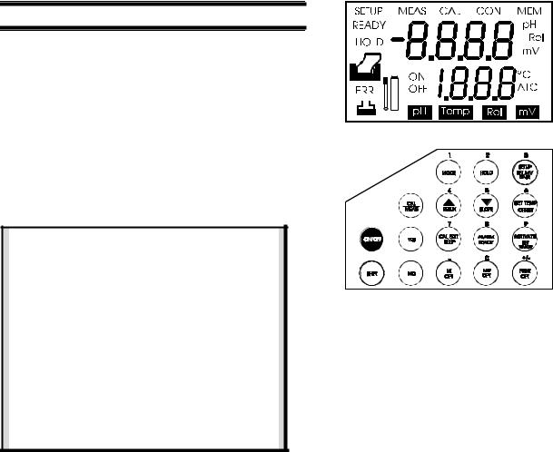
2.2Customized LCD
The pH 1000/ 2500 bench meter is characterized by large dual custom LCD (Liquid Crystal Display). The display has also mode annunciators for pH, temperature, relative mV and mV readings. The secondary (lower) display shows the temperature readings simultaneously with the primary (upper) display of measured mode. Special annunciators such as graphical symbols, error messages, measurement units and modes of operation are arranged around the primary and secondary displays to give a comprehensive display. The integration of graphics and error messages into the LCD provides you a higher level of user-friendliness and easy readability.
2.3Slide Out Card
A plastic slide out card is provided at the bottom of the bench meter. The function of this card is to provide a quick guide to the functions of the individual keys as well as to provide a useful trouble shooting reference.
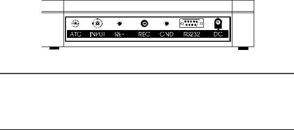
2.4Rear Instrument Panel
The pH 1000/ 2500 bench meter provides a set of connectors for the various accessories commonly used. In addition to all the connectors, pH 1000/ 2500 bench meter has an additional RS232C port to allow for data transmission between the meter and a printer or computer, Furthermore; it can be remotely controlled using a software from Eutech Instruments. Listed as follows are various connections available.
1
Instruction Manual |
pH 1000/ 2500 |
Connector |
Function |
ATC |
For phono jack connection from the temperature probe for Automatic Temperature |
|
Compensation. The probe should be a thermister type probe. |
INPUT |
For connecting sensors with a BNC connector to the meter. The meter accepts any pH, |
|
ORP or ISE electrode with a BNC connector. Always make sure that the connector is |
|
clean and dry. |
|
|
REF |
For connection to the pin tip type reference electrode normally used with half cell (mono) |
|
type pH or ISE electrodes. |
|
|
REC |
For connection to the strip chart recorder. |
|
|
GND |
For connection to the ground earth jack (standard pin tip connectors). |
|
|
RS232C |
For connection to the RS232C serial port. |
|
|
DC |
For connection to the AC power source to the power jack (DC). |
|
|
|
|
Rear View of the Meter
2.5AC/DC-Adapter
AC/DC adapters convert the power mains voltage 120/220 VAC to low DC voltage for the pH 1000/ 2500 bench meter operation. Two basic models of adapters are available depending upon power supply specification of each country. See accessories section.
2.6Electrode
Electrode is one of the most important parts of the meter. The electrode glass membrane is fragile and must be handled with care. A protective rubber cap containing a suitable storage solution to protect the glass membrane and to maintain activation of the glass membrane covers the pH electrode provided with the meter (when ordered). A special protective guide for use during measurements is enclosed to offer added protection against damage to the pH electrode glass bulb during operation. Maintenance of electrode is necessary from time to time. Please refer to Section 14 on Electrode Care.
2

Instruction Manual |
pH 1000/ 2500 |
3 KEYPAD FUNCTIONS
The pH 1000/ 2500 bench meter is equipped with large tactile response keypad for ease of use. All keys have primary function with some keys having secondary functions.
3.1Primary & Secondary Functions of Keypad
ON/OFF
Primary Function |
Turns meter on or off. |
|
|
Secondary Function |
None |
Numeric Value |
None |
|
|
|
|
SHIFT
Primary Function |
Press to access the secondary functions of the meter. |
Secondary Function |
None |
Numeric Value |
None |
|
|
YES
Primary Function |
Enter numeric values, confirm calibration points, or confirm and scroll program options |
|
or values selected. |
|
|
Secondary Function |
None |
Numeric Value |
None |
|
|
NO
Primary Function |
Use to cancel incorrectly selected numeric value or selection made. |
Secondary Function |
None |
|
|
Numeric Value |
None |
3

Instruction Manual |
pH 1000/ 2500 |
CAL/MEAS
Primary Function |
Press to toggle between measurement and calibration modes of the meter - pH, |
|
Temperature, mV, Relative mV and Ion. Also use as exit from SETUP mode, |
|
secondary functions and to abort operation while in calibration mode. |
|
|
Secondary Function |
None |
Numeric Value |
None |
|
|
1 / MODE
Primary Function |
Select one of four measurement modes: pH/mV/Relative mV/Ion. |
|
|
Secondary Function |
None |
Numeric Value |
1 |
|
|
|
|
2 / HOLD
Primary Function |
Freeze the displayed value. Allow you to print the held reading or store it into memory. |
Secondary Function |
None |
|
|
Numeric Value |
2 |
|
|
3 / SETUP / REL MV BASE
Primary Function |
Enter SETUP mode of the meter for customization of meter functions as well as view |
|
some diagnostic functions. |
|
|
Secondary Function |
Display the Relative mV base value while in Relative mV mode and Ion Electrode |
|
Slope while in the Ion mode. |
|
|
Numeric Value |
3 |
|
|
4 / ∆ / RESLN
Primary Function |
Select next higher pH buffer values in the pH calibration mode. Also used to scroll |
|
through SETUP mode options. |
|
|
Secondary Function |
Toggle the pH resolution between 0.01 pH and 0.1 pH. |
Numeric Value |
4 |
|
|
|
|
5 / / SLOPE
Primary Function |
Select the next lower pH buffer value option in pH calibration mode. Also used to |
|
scroll through some SETUP mode options. |
|
|
Secondary Function |
Display the percentage slope of the pH electrode when in the pH mode. While in Ion |
|
mode, it displays slope of ion electrode in mV/decade. |
Numeric Value |
5 |
|
|
|
|
6 / SET TEMP / OFFSET
Primary Function |
Press to calibrate ATC temperature probe or to set manual temperature. |
Secondary Function |
Displays the offset of pH electrode. This is useful as a diagnostic function to |
|
determine the quality of the probe that is connected to the meter. |
Numeric Value |
6 |
|
|
4

Instruction Manual |
pH 1000/ 2500 |
7 / CAL EDIT / BEEP
Primary Function |
Press to edit pH buffer value while you are in pH calibration mode. |
Secondary Function |
Turns on or off ‘beep’ sound whenever a key-press is depressed. |
|
|
Numeric Value |
7 |
|
|
8 / ALARM / READY
Primary Function |
Enter the high and/or low alarm values. |
|
|
Secondary Function |
Turns on or off the READY function. |
Numeric Value |
8 |
|
|
|
|
9 / ACTIVATE / SET TIMER
Primary Function |
Press to start timer countdown. |
Secondary Function |
Sets the time interval. |
Numeric Value |
9 |
|
|
|
|
. / MI / OPT
Primary Function |
Stores the displayed value into memory. |
Secondary Function |
Activate different Memory Input Options, these include: |
|
Data Log on Ready |
|
Data Log on Time Interval |
|
Set Time Interval for Data Log |
Numeric Value |
. (decimal point) |
|
|
0 / MR / OPT
Primary Function |
Recalls stored values from the memory in the Last-In-First-Out (LIFO) sequence. |
|
|
Secondary Function |
Activate different Memory Recall options. There are two options: |
|
Print all memory data |
|
Clear memory |
Numeric Value |
0 |
|
|
+/- / PRINT / OPT
Primary Function |
Output the displayed data through the serial/RS232C port. Can be activated in the |
|
measurement, HOLD functions and memory recall functions. |
|
|
Secondary Function |
Sets the different print options. There are three options: |
|
Print on ready |
|
Print on time interval |
|
Set print time interval |
Numeric Value |
+/- |
|
|
5
Instruction Manual |
pH 1000/ 2500 |
4 STARTING UP THE METER
4.1Connecting the Sensor Electrode
Slide the sensor electrode connector of the electrode over the INPUT BNC socket. Then push the connector into the socket and turn the connector clockwise to lock into position. Do not use excessive force. This applies to combination pH/ORP/ISE electrodes. For half-cell sensors where a reference electrode is used, connect the sensor connector to socket marked (REF). Always ensure that the connectors are dry when connection is done.
4.2Connecting the Temperature Probe
The temperature probe uses a phono jack to connect with the socket marked ATC on the meter. Insert the jack directly into the socket until it is firmly seated.
4.3Connecting the AC/DC Adapter
Ensure that the power to the AC/DC adapter is switched off. Slide the AC/DC adapter jack into the socket marked DC of the meter until it is firmly seated. For AC/DC adapter always ensure that the power mains voltage matches that of the adapter used. AC/DC adapters used should have the following specifications or settings. Output:- Voltage: 9 V DC Current: 500 mA.
NOTE: Ensure that the input power mains voltage (120/220 V) matches your adapter requirements.
4.4Connecting the Chart Recorder
The meter provides a recorder output of +/- 2000 mV for transmission of readings either to a chart recorder or to a data acquisition device (Analog/Digital Cards). When the chart recorder is in operation, continuous absolute mV readings will be charted. Note that readings are independent of the operating mode and is uncompensated and set to a one to one (1:1) ratio.
Where the charting is made in reference to ground potential, a cable is connected from the GND port of the meter to the chart recorder. Plug the phono connector to the meter at the designated port (marked REC). The tip (inner) connection should be wired to the high side of the recorder and the sleeve (outer) side should be wired to the low side of the recorder.
4.5Connecting RS232C Cable
Noting the orientation of RS232C connector, insert the 9-pin male connector from your device (a printer or computer) into the RS232C port (marked RS232) of the meter. Fasten the RS232C connector using the two screws at the side of the male RS232C connector. Do not over-tighten.
6
Instruction Manual |
pH 1000/ 2500 |
5 TURNING THE METER ON AND OFF
Once the AC/DC adapter is connected and powered on, the meter beeps and the full LCD lights up for a few seconds to display all segments as a self-diagnostic test of the LCD. Then the meter will display the current time.
To access the meter functions, press ON/OFF key. The meter beeps and performs a diagnostic test before going into the pH measurement [MEAS] mode. To turn the meter off, press ON/OFF key within the operation mode. The meter performs a self-diagnostic LCD test before displaying the current time.
IMPORTANT :
Remember to remove the protective cap from the electrode tip prior to measurement. Replace it in place after use or store electrode in some storage solution to avoid possible dehydration of glass bulb which may result in slow response.
In any case if the electrode is not in use for long period, condition the electrode by soaking into tap water for 1-2 hours before use.
Make sure to wash electrodes/probes before/after each sample measurements to prevent any carry-over of samples.
7
 Loading...