


 Loading...
Instruction Manual
CyberScan pH 10 & pH 100
Hand-held pH / mV / Temperature / RS 232 Meter
pH 10 Meter
pH/mV/°C
pH 100 Meter
pH/mV/°C/RS 232
68X007106 |
Technology Made Easy ... |
09/2001 rev 4
PREFACE
This manual serves to explain the use of the Standard CyberScan series hand-held meters. The models covered are the CyberScan pH 10 and the CyberScan pH 100 hand-held meters.
The manual functions in two ways, firstly as a step by step guide to help the user operate the meter. Secondly, it serves as a handy reference guide.
This instruction manual is written to cover as many anticipated applications of the CyberScan pH meters as possible. If there are doubts in the use of the CyberScan pH 10/100 meters, do not hesitate to contact the nearest Eutech Instruments Authorized Distributor.
Eutech Instruments cannot accept any responsibility for damage or malfunction to the meter caused by improper use of the instrument.
Remember to fill in the guarantee card and mail it back to your authorized distributor or Eutech Instruments Pte Ltd (address, contact details, email and homepage information are found on the back page of this manual).
The information presented in this manual is subject to change without notice as improvements are made, and does not represent a commitment on the part of the Eutech Instruments Pte Ltd.
Note: Lotus® 1-2-3 is a registered trademark of Lotus Corporation.
Excel ® is a registered trademark of Microsoft Corporation.
Copyright ©1993 Eutech Instruments Pte. Ltd. All rights reserved.
Revised in September 2001, revision 4 (version 5).
TABLE OF CONTENTS
1 |
INTRODUCTION |
1 |
|
2 DISPLAY AND KEYPAD FUNCTIONS |
2 |
|
|
2.1 |
Display |
2 |
|
2.2 |
Keypad |
3 |
|
3 |
PREPARATION |
5 |
|
3.1 |
Inserting the Batteries |
5 |
|
3.2 |
Connecting the pH Electrode, Temperature Probe & Electrode Holder |
6 |
|
3.3 |
Connecting the AC/DC Adapter |
8 |
|
3.4 |
Connecting the RS232C Cable (Only For CyberScan pH 100) |
9 |
|
4 |
CALIBRATION |
11 |
|
4.1 |
Preparing the Meter for Calibration |
11 |
|
4.2 |
pH Calibration with ATC |
12 |
|
4.3 |
pH Calibration (without ATC) |
14 |
|
4.4 |
Temperature Calibration |
15 |
|
4.5 |
Calibration Procedure for Relative mV Measurements (For pH 100 Only) |
17 |
|
4.6 |
Erasing Calibrated Values (For pH 100 only) |
18 |
|
5 |
MEASUREMENT |
19 |
|
5.1 |
Automatic Temperature Compensation |
19 |
|
5.2 |
Manual Temperature Compensation |
20 |
|
5.3 |
Taking Measurements |
21 |
|
6 |
HOLD FUNCTION |
22 |
|
7 MEMORY FUNCTION (FOR pH 100 ONLY) |
23 |
||
7.1 |
Memory Input |
23 |
|
7.2 |
Memory Recall |
24 |
|
8 PRINT FUNCTION (FOR pH 100 ONLY) |
25 |
||
8.1 |
Using the CyberScan pH 100 With The Printer |
25 |
|
8.2 |
Sending Data To Computer |
26 |
|
9 ADVANCED SETUP FUNCTIONS (FOR pH 100 ONLY) |
28 |
||
9.1 |
Program 1 – Software Initialization |
29 |
|
9.2 |
Program 2 – Electrode Data |
30 |
|
9.3 |
Program 3 –Meter Configuration |
32 |
|
9.4 |
Program 4 – Communication Setup |
34 |
|
10 CYBERCOMM PORTABLE - DATA ACQUISITION SOFTWARE |
|
|
|
|
(DAS FOR pH 100 ONLY) |
36 |
|
10.1 |
System Requirements |
36 |
|
10.2 |
Loading CYBERCOMM PORTABLE |
36 |
|
10.3 |
Running CYBERCOMM PORTABLE |
42 |
|
10.4 |
Capturing And Printing Data Into Computer Using CYBERCOMM PORTABLE |
46 |
|
10.5 |
Trouble-shooting Guide |
47 |
|
11 |
ELECTRODE CARE |
48 |
|
11.1 |
Electrode Maintenance |
48 |
|
11.2 |
Electrode Cleaning |
49 |
|
11.3 |
Electrode Activation |
49 |
|
11.4 |
Rejuvenation Procedure |
49 |
|
12 |
ERROR MESSAGES |
51 |
|
13 |
TROUBLE-SHOOTING |
52 |
|
14 INFORMATION ON pH MEASUREMENT & ELECTRODE |
53 |
||
14.1 |
pH Measurements |
53 |
14.2 |
Use of Standard pH Buffers |
54 |
14.3 |
Standard pH Buffers |
55 |
15 |
LIST OF ACCESSORIES |
56 |
15.1 |
Replacement Meter and Meter accessories |
56 |
15.2 |
Calibration Solutions |
57 |
15.3 |
Ion Selective Electrodes (ISE) |
57 |
15.4 |
pH & ORP Electrodes |
58 |
16 |
METER SPECIFICATIONS |
59 |
17 |
ADDENDUM 1: FACTORY DEFAULT SETTINGS (pH 100 ONLY) |
60 |
18 |
WARRANTY & RETURN OF ITEMS |
61 |

1 INTRODUCTION
Thank you for selecting Eutech Instruments standard CyberScan pH 10/100 meter. These meters are microprocessor-based instrument and are designed to be handy, capable of allowing one-hand operation. Each has a large custom dual LCD for clear and easy reading. It is a unique and intelligent instrument that has the capability to cater to the preferences of the discerning individual.
Both meters have many user-friendly features – all of which are completely accessible through the splash-proof membrane keypad. Your meter includes a temperature probe (EC-PHTEM- 01P), electrode holder, built-in meter stand and batteries. Eutech Instruments offer a wide selection of pH and ORP electrodes. Refer to “Accessories” section for more information.
The basic model is the CyberScan pH 10 which is capable of measuring pH, Temperature, and millivolt (mV).
The deluxe model is the CyberScan pH 100 which measures pH, Temperature, millivolt (mV) and relative millivolt (Rel mV). It has many advanced features and allows you to customize the meter settings. It also has a RS232C port that allows the meter to be connected to a computer or a printer via a cable for transferring data.
For power requirement, you can either use 4 AAA-sized batteries or an AC/DC power adapter (sold separately).
Please read this manual thoroughly before operating your meter.
1

2 DISPLAY AND KEYPAD FUNCTIONS
2.1Display
The LCD has a primary and secondary display.
•The primary display shows the measured pH or ORP values.
•The secondary display shows the measured temperature.
The display also shows error messages, keypad functions and program functions.
|
|
|
|
|
|
|
|
|
|
|
|
|
|
|
|
|
|
|
|
|
|
|
|
|
|
|
|
|
|
|
|
|
|
|
|
|
|
|
|
|
|
|
|
|
|
|
|
|
|
|
|
|
|
|
|
|
|
|
|
|
|
|
|
|
|
|
|
|
|
|
|
|
|
|
|
|
|
|
|
|
|
|
|
|
|
|
|
|
|
|
|
|
|
|
|
|
|
|
|
|
|
|
|
|
|
|
|
|
|
|
|
|
|
|
|
|
|
|
|
|
|
|
|
|
|
|
|
|
|
|
|
|
|
|
|
|
|
|
|
|
|
|
|
|
|
|
|
|
|
|
|
|
|
|
|
|
|
|
|
|
|
|
|
|
|
|
|
|
|
|
|
|
|
|
|
|
|
|
|
|
|
|
|
|
|
|
|
|
|
|
|
|
|
|
|
|
|
|
|
|
|
|
|
|
|
|
|
|
|
|
|
|
|
|
|
|
|
|
|
|
|
|
|
|
|
|
|
|
|
|
|
|
|
|
|
|
|
|
|
|
|
|
|
|
|
|
|
|
|
|
|
|
|
|
|
|
|
|
|
|
|
|
|
|
|
|
|
|
|
|
|
|
|
|
|
|
|
|
|
|
|
|
|
|
|
|
|
|
|
|
|
|
|
|
|
|
|
|
|
|
|
|
|
|
|
|
|
|
|
|
|
|
|
|
|
|
|
|
|
|
|
|
|
|
|
|
|
|
|
|
|
|
|
|
|
|
|
|
|
|
|
|
|
|
|
|
|
|
|
|
|
|
|
|
|
|
|
|
|
|
|
|
|
|
|
|
|
|
|
|
|
|
|
|
|
|
|
|
|
|
|
|
|
|
|
|
|
|
|
|
|
|
|
|
|
|
|
|
|
|
|
|
|
|
|
|
|
|
|
|
|
|
|
|
|
|
|
|
|
|
|
|
|
|
|
|
|
|
|
|
|
|
|
|
|
|
|
|
|
|
|
|
|
|
|
|
|
|
|
|
|
|
|
|
|
|
|
|
|
|
|
|
|
|
|
|
|
|
|
|
|
|
|
|
|
|
|
|
|
|
|
|
|
|
|
|
|
|
|
|
|
|
|
|
|
|
|
|
|
|
|
|
|
|
|
|
|
|
|
|
|
|
|
|
|
|
|
|
|
|
|
|
|
|
|
|
|
|
|
|
|
|
|
|
|
|
|
|
|
|
|
|
|
|
|
|
|
|
|
|
|
|
|
|
|
|
|
|
|
|
|
|
|
|
|
|
|
|
|
|
|
|
|
|
|
|
|
|
|
|
|
|
|
|
Figure 1: Full LCD Screen |
|
|
|
|
|
|
|
|
|
|
|
|
|
|
|
|||||||
1. SETup mode indicator |
|
9. pH buffer selection indicator |
|
|
|
16. ON & OFF indicator |
|||||||||||||||||||||||||||||||
2. MEASurement mode indicator |
|
10. Temperature indicator |
|
|
|
17. Low battery indicator |
|||||||||||||||||||||||||||||||
3. CALibration indicator |
|
11. Automatic Temperature |
|
|
|
18. Probe indicator |
|||||||||||||||||||||||||||||||
|
|
|
|
|
|
|
|
|
|
|
|
|
|
|
Compensation indicator |
|
|
|
|
|
|
|
|
|
|
|
|
|
|
|
|||||||
4. CONfirm indicator |
|
12. mV measurement mode |
|
|
|
19. Buffer indicator |
|||||||||||||||||||||||||||||||
|
|
|
|
|
|
|
|
|
|
|
|
|
|
|
indicator |
|
|
|
|
|
|
|
|
|
|
|
|
|
|
|
|||||||
5. MEMory recall mode indicator |
|
13. Rel mV measurement mode |
|
|
|
20. ERRor indicator |
|||||||||||||||||||||||||||||||
(For pH 100 only) |
|
|
|
indicator (For pH 100 only) |
|
|
|
|
|
|
|
|
|
|
|
|
|
|
|
||||||||||||||||||
6. pH indicator |
|
14. Temperature measurement |
|
|
|
21. Printer indicator (For pH 100 |
|||||||||||||||||||||||||||||||
|
|
|
|
|
|
|
|
|
|
|
|
|
|
|
mode indicator |
|
|
|
|
|
only) |
||||||||||||||||
7. Relative mV indicator (For pH |
|
15. pH measurement mode |
|
|
|
22. HOLD indicator |
|||||||||||||||||||||||||||||||
100 only) |
|
|
|
indicator |
|
|
|
|
|
|
|
|
|
|
|
|
|
|
|
||||||||||||||||||
8. mV indicator |
|
|
|
|
|
|
|
|
|
|
|
|
|
|
23. READY indicator |
||||||||||||||||||||||
2

2.2Keypad
A large membrane keypad with tactile feedback makes the instrument easy to use. Each button, when pressed, has a corresponding graphic indicator on the LCD (Figure 1). Some buttons have several functions depending on its mode of operation.
Key |
|
Function |
ON/OFF |
Powers on and shuts off the meter. The meter will start in pH measurement mode. |
|
HOLD |
Freezes the measured reading. To activate, press HOLD while in measurement |
|
|
mode. To release, press HOLD again. |
|
MODE |
Selects the measurement parameter. Default is pH measurement. Press MODE to |
|
|
toggle between pH, Temperature, Rel mV (only pH 100), mV, & back to pH |
|
|
measurement mode. |
|
|
|
|
CAL/MEAS |
Toggles between Calibration and Measurement mode. |
|
|
1. |
If you are in pH measurement mode, press CAL/MEAS to enter pH calibration |
|
|
mode. |
|
2. |
If you are in temperature measurement mode, press CAL/MEAS to enter |
|
|
temperature calibration mode. |
|
3. |
If you are in Rel mV (only in pH 100) measurement mode, press CAL/MEAS to |
|
|
enter Rel mV measurement calibration mode. |
|
While in SETup (only in pH 100) menu, pressing CAL/MEAS takes you out and into |
|
|
the measurement mode. |
|
CON |
CONfirm function: Press to confirm values in Calibration mode and to confirm |
|
|
selections in SETup mode. |
|
!/ " In Calibration mode:
1.If you are in pH calibration mode, press ! or " key scrolls up or down the buffer calibration values.
2.If you are in temperature calibration mode, press ! or " key to adjust temperature values in °C.
3.If you are in Rel mV (only in pH 100) calibration mode, press ! or " key to adjust mV values.
In SETUP mode (only in pH 100):
Press ! or " key to scroll through options in each SETup programs.
MI / MR (only In measurement mode (pH, Rel mV or mV) press MI (memory input) to store values in pH 100) with its corresponding temperature values in the memory. Press MR (memory recall)
to retrieve data from memory.
Allows you to print current measurement to either the printer or the computer.
(only in pH 100)
SETUP (only Takes you into the SETUP mode. This mode lets you customize meter preference in pH 100) and defaults, view calibration, electrode offset data, clear memory, change pH
resolution, and communication protocol setting.
3
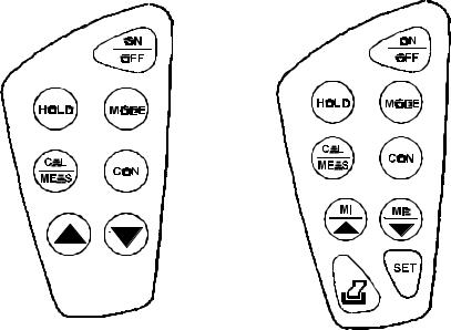
Figure 2: Keypad of pH 10 meter
Figure 3: Keypad of pH 100 meter
4
3 PREPARATION
3.1Inserting the Batteries
The CyberScan is packaged with 4 “AAA” alkaline batteries required for operation. To insert
the batteries into the CyberScan, follow the procedure outlined below.
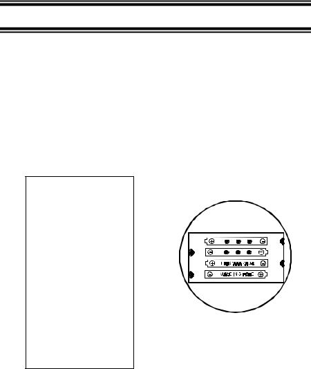
1.Use a Phillips Head screwdriver, remove the two screws (Figure 4) with the hinge closed.
2.Remove the battery cover. Note the polarity and insert the batteries into the battery compartment correctly (Figure 5).
3.Replace the battery cover into its position and screw back using the two screws removed earlier.
Your CyberScan hand-held meter is now ready for operation.
Figure 5: Battery position
Figure 4: Take out battery cover by removing 2 screws
5

3.2Connecting the pH Electrode, Temperature Probe & Electrode Holder
The Eutech Instruments CyberScan pH 10/100 meter uses any standard pH, ORP, or Ion Selective Electrode (ISE) with a BNC connector. For Automatic Temperature Compensation (ATC), this meter requires a temperature probe with a phono-jack connector.
NOTE: It is important that water does not get onto the BNC connector. Also avoid touching the connector with soiled hands.
3.2.1To connect pH, ORP or ISE electrode
1.Slide the electrode connector of the electrode over the BNC connector socket on the meter.
2.Make sure the slots of the connector are in line with the posts of the socket.
3.Slide the BNC connector of the probe over (Figure 6).
4.Rotate and push connector clockwise until it locks.
5. To remove electrode, push and rotate |
Figure 6: Connect pH or ORP electrode using BNC |
the connector anti-clockwise. |
|
6.While holding onto the metal part of
the connector, pull it away from the meter.
7.Be careful not to use excessive force.
CAUTION: Do not pull on the probe cord or the probe wires might disconnect.
Refer to “Accessories” section for information on temperature probe and other electrodes.
3.2.2To connect the temperature probe:
The temperature probe (provided) uses a phono jack to connect with the socket on the CyberScan. Insert the jack fully into the socket (Figure 7).
Figure 7: Connecting the temperature probe
6
3.2.3Attaching the electrode onto the electrode Holder
The CyberScan pH meter is packed with two electrode holders (provided). They are designed for easy use and installation. Care must be taken to avoid use of excessive force in the process of attaching these components.
1.Locate the slot on the right-hand side of the meter.
2.Gently slide the flange of the holder into the slot on the meter. Make sure the holder is secured properly into the slot (Figure 8).
3.You can attach the electrode holder in different positions (Figure 10).
Figure 8: Slide in the electrode holder
3.2.4To attach a second electrode holder:
The electrode holder is designed such that you can attach one holder onto another. Up to two electrodes (using the BNC connector and phono-jack) can be used with the CyberScan meter at any one time.
1.Align the flange of the second electrode holder with the slot of the first holder (Figure 9).
2.Slide the flange of the second holder into the slot of the first holder until the tops of the holders are aligned and secure.
Figure 9: Connecting 2 electrode holders together
7

3.2.5Insert the electrode into the holder
1.Do not use excessive force when inserting electrodes into the holders.
2.Insert the pH electrode into the opening of the first holder until the top housing of the electrode touches the top of the holder.
3.If you are using a separate temperature probe, insert the probe into the opening of the second holder until the ridge on the housing touches the top of the holder.
NOTE: The holder is designed for probes 12 mm in diameter. Electrodes larger than 12 mm may not fit in the holder. Forcing the electrode into the opening may damage the holder or your electrode.
The electrode holders can be attached in different positions for greater flexibility in measurement and storage purposes. Simply slide out the electrode holders and reoriented into appropriate
Figure 10: Different positions using electrode holder
orientation before putting into position.
3.3Connecting the AC/DC Adapter
Besides using four AAA-sized batteries as power source, the CyberScan pH 10/100 meter can also operate from the power mains using an AC/DC power adapter either at 120/220 VAC (sold separately). This is extremely useful if you have an A.C. power source available (e.g. laboratory).
Before plugging in, switch off the meter and the power source of adapter. This is a safety precaution that should be adhered to
safeguard your CyberScan meter.
Figure 11: Putting the AC Power Adapter
1.Switch off the meter and power sources.
2.Select the correct voltage of AC/DC Adapter. See Figure 11.
NOTE: Output Voltage: 12 V D.C.; Current: 500 mA. Ensure that the input mains voltage (120/240 VAC) matches your adapter requirements.
3.Insert the D.C. jack into the socket and switch on the power to the adapter, followed by the CyberScan meter.
8

3.4Connecting the RS232C Cable (Only For CyberScan pH 100)
The CyberScan pH 100 meter provides a RS232C output for you to transmit your readings either to a printer or a computer via a cable. This is useful in instances where the CyberScan meter is used for continuous monitoring of a certain process or experiment. Data output to the printer or the computer can then be evaluated.
The data is output in the ASCII format. This format allows the data to be imported by a wide variety of software that read ASCII data (e.g. Microsoft’s Excel, Lotus, Quattro-pro etc.). Eutech Instruments provides a complimentary Data Acquisition Software (DAS) that captures data transmitted into an ASCII file for later use.
Figure 12: Location of
RS232C Port (Only in pH
100)
1.Open the printer port cover located at the bottom end of the meter. Do not use excessive force when doing this. See Figure 12.
2.Noting the orientation of the RS232C connector, plug the male connector into the RS232C port of the CyberScan.
3.Fasten the RS232C connector by fastening the two screws at the side of the male RS232C connector.
3.4.1RS232C Configuration
The CyberScan pH 100 meter has a 9 pin female RS232C connector with the following pinout:
PIN NO. |
DESCRIPTION |
|
|
1 |
- |
|
|
2 |
Transmit Data |
|
|
3 |
- |
|
|
4 |
DSR (Data Set Ready) |
|
|
5 |
GND |
|
|
6 |
- |
|
|
7 |
CTS (Clear to Send) |
|
|
8 |
- |
|
|
9 |
- |
|
|
A one-to-one connection can be made with a 9 pin RS232C port of the computer.
9

Figure 13: Pin number position of the 9-pin RS 232C port
In case CyberScan pH 100 meter’s output has to be sent to a 25 pin RS232C connector, the
following cable configuration may be used:
CyberScan pH 100 |
25 pin connector |
2 (TxD) |
(RxD) 3 |
4 (DSR) |
(DTR) 20 |
5 (GND) |
(GND) 7 |
7 (CTS) |
(RTS) 4 |
1.CyberScan pH 100 uses hardware handshake i.e. CyberScan pH 100 expects both DSR and CTS lines to be active before it sends data.
2.If the [PRINT] key is pressed while the printer is not ready or if the printer is off, the CyberScan pH 100 meter displays error message by showing both the printer and the ERR annunciators blinking alternately, and awaits the printer to be ready (Figure 14).
3.While the meter is displaying printer error, you
may press CAL/MEAS key to return to the
measurement mode.
Figure 14: Error in printing
10

4 CALIBRATION
4.1Preparing the Meter for Calibration
Before starting calibration, make sure you are in the correct measurement mode. When you switch on the meter, the meter starts up in the pH measurement mode.
Before calibrating, select the correct mode by pressing the MODE key. There are 4 modes:
[pH] |
for pH measurements, |
|
|
[Temp] |
for Temperature measurements, |
|
|
[Rel] [mV] |
for Relative mV measurements (only for pH 100 meter) |
|
|
[mV] |
for millivolt measurements. |
|
|
Be sure to remove the protective electrode storage bottle or rubber cap of the electrode before calibration or measurement. If the electrode has been stored dry, wet the electrode in tap water for 10 minutes before calibrating or taking readings to saturate the pH electrode surface and minimize drift.
Wash your electrode in deionized water after use, and store in electrode storage solution. If storage solution is not available, use pH 4.01 or 7.00 buffer solution.
Do not reuse buffer solutions after calibration. Contaminants in the solution can affect the calibration, and eventually the accuracy of the measurements. Refer to Accessories for information on Eutech Instruments pH buffer solutions.
It is recommended that you perform at least a 2-Point Calibration using standard buffers that adequately cover the expected measurement range prior to measurement. 1-Point Calibration can also be used for quick measurements. Make sure that the calibration point is close to the sample value to be measured.
The CyberScan pH 10 & pH 100 meters are capable of multi-point calibration to ensure enhanced accuracy throughout the pH measurement range. The number of pH calibrations points and pH buffer standards used are:
Meter |
Number of Calibration Points |
Buffer Points (USA standard) |
|
|
|
pH 10 |
Up to 3 points |
pH 4.01, 7.00 & 10.01 |
|
|
|
pH 100 |
Up to 5 points |
pH 1.68, 4.01, 7.00, 10.01 & 12.45 |
|
|
|
11
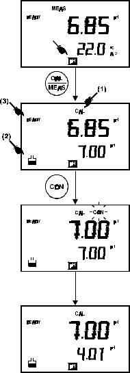
4.2pH Calibration with ATC
To activate the Automatic Temperature Compensation (ATC), simply plug in the temperature probe into the phono jack. The ATC indicator will be displayed on the LCD (Figure 15). If the ATC indicator is not displayed, it indicates that the temperature probe is either not properly connected to the instrument or is faulty.
1.Switching ‘ON’ the meter by pressing the
ON/OFF key.
2.All the LCD segments will be displayed momentarily for a few seconds to check that all segments are in working condition. Then, the LCD will switch to the [pH] measurement mode.
3.Select the [pH] mode using the MODE key. (See Figure 15 on right).
4.Rinse the electrode well with deionized water or rinse solution. (Do not wipe the electrode with tissue paper as this may cause a build-up of electrostatic charge on the glass surface!).
5.Dip the probe into the calibration buffer. The end of the probe must be completely immersed into the sample. Stir the probe gently to create a homogeneous sample.
6.Press the CAL key to calibrate the meter.
7.The display will show the [CAL] mode and the buffer icon as shown (see [1] & [2] in Figure 15).
8.The primary display will show the measured reading while the secondary display will indicate that pH 7.00 is ready for calibration.
9.Wait for the measured pH value to stabilize. The READY annunciator will light up. See [3] in Figure 15.
Figure 15: pH Calibration at pH 7.00
12

NOTE: In pH 100 meter, you can program the meter to turn off the ‘READY’
indicator through the SETup mode.
10.Press the CON key to confirm the calibration. The ‘CON‘ indicator flashes for one second and disappears.
11.Upon confirmation, the instrument is calibrated to the buffer indicated in the secondary display.
12. The secondary display automatically scrolls to the next pH buffer calibration option i.e. pH 10.01.
13. For 1-Point Calibration, this can be ignored and you can exit to the [MEAS] mode by selecting the CAL/MEAS key.
NOTE: The ‘Or’ indicator flashes if the selected buffer value is not within +/- 0.50 pH from the measured pH value.
14. To calibrate 2 or more points, press the Ml/! and MR/" key to scroll through the various buffer pH options.
15. Select the second pH buffer for calibration accordingly. Repeat steps 4 to 14 above.
16. Once calibration is confirmed at the second point,
Figure 16: Calibration for second point
you can proceed to calibrate at the third point without the need to return to Measurement mode. Just select the desired buffer by using Ml/! or MR/" key.
NOTE: For pH 100 meter you can check on which buffer calibration points were being calibrated using Program 2.2 under SETUP mode (see section 9.2.1 on Electrode Data).
NOTE: To exit from pH calibration mode without confirming calibration, DO NOT press CON in step 11. Press CAL/MEAS instead.
If the selected buffer value is not within ±1.0 pH from the measured pH value: the electrode and buffer icon blink and the ERR annunciator appears in the lower left corner of the display.
Figure 17: Err message and electrode icon will appear if incorrect buffer are used
13
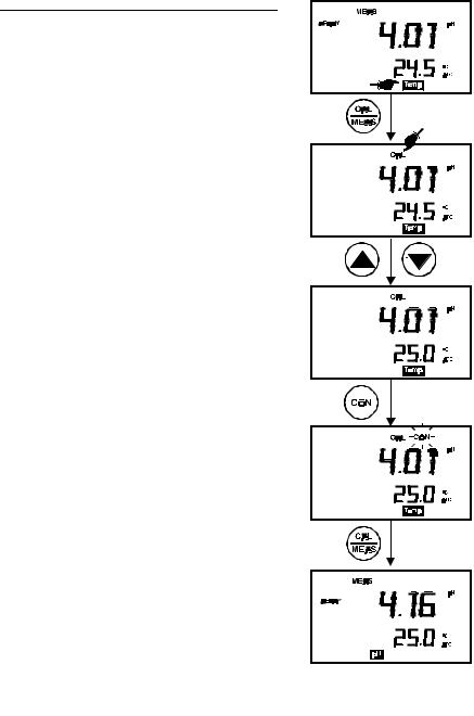
4.3pH Calibration (without ATC)
When the CyberScan meter is not used with a temperature probe, it is necessary to calibrate
the temperature first prior to pH calibration.
1.Calibrate for temperature as described in the procedure in Section 4.4.1 - Temperature Calibration Without ATC Probe.
2.Next, proceed with the pH calibration as described in the above section.
3.The meter is now calibrated at a fixed temperature.
NOTE: To exit this program without confirming the temperature calibration value, DO NOT
press CON. Press CAL/MEAS instead.
14
4.4 Temperature Calibration
The temperature sensor is factory calibrated. Calibrate the temperature probe only if you suspect the temperature errors that may have occurred over a long period of time or if you have a replacement temperature probe. This procedure offers offset adjustment of probe to ensure more accurate temperature measurement.
In the event where there is no temperature sensor, this procedure can also be performed for Manual Temperature Compensation (MTC).
4.4.1 Temperature Calibration Without ATC Probe
1. Switch the meter on. Press the MODE key to select temperature mode, [Temp].
2. Press the CAL/MEAS key to enter temperature calibration mode. The primary display indicates the pH value, and the secondary display shows the temperature.
3. Press ! or " key to select temperature value that matches the temperature reading shown in your reference thermometer.
4. Once you have selected the correct temperature, press CON key to confirm.
5. The CON indicator flashes for one second and disappears.
6. Press CAL/MEAS key to return to the pH measurement mode.
NOTE: To exit this program without confirming the temperature calibration value, DO NOT press CON. Press CAL/MEAS instead.
Figure 18: Temperature
Calibration
15
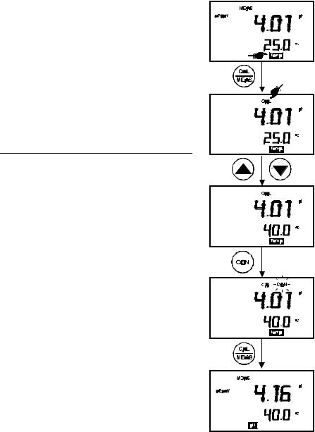
4.4.2 Temperature Calibration With ATC Probe
1. Make sure the ATC probe is attached to the meter. Refer to Figure 7 in Section 3.2.2.
2. Switch the meter on. Note the ATC indicator.
3. Press the MODE key to select temperature mode, [Temp].
4. Dip the ATC probe into a solution of known temperature (i.e. a temperature bath). Allow time for the temperature probe to stabilize.
5.Press the CAL/MEAS key to enter temperature
calibration mode. The primary display indicates the pH value, and the secondary display shows the temperature.
6. Press ! or " key to select temperature.
7. Once you have selected the correct temperature, press CON key to confirm.
8. The CON indicator flashes for one second and disappears.
9.Press CAL/MEAS key to return to the pH
measurement mode.
NOTE: To exit this program without confirming the temperature calibration value, DO NOT press CON. Press CAL/MEAS instead.
Figure 19: Temperature calibration with temperature probe
16
4.5Calibration Procedure for Relative mV Measurements (For pH 100 Only)
Relative millivolt calibration is used in ISE measurements, where it is common to use the lowest concentration mV value as the base value for measurements. All subsequent measurements will then be based on this reference value. For Relative mV calibration, carry out the following procedure:
1.Press the MODE key to enter the Relative mV mode.
2.The primary display shows the absolute mV reading while secondary display shows the
temperature.
3.On pressing the CAL key, the calibration mode is activated. The ‘CAL’ indicator is displayed on the LCD. The rest of the display remains the same.
4.With the Ml/! and MR/" keys, adjust the displayed absolute mV value to the base value required e.g. 350.0 mV (Figure 20).
NOTE: To exit this mode or re-enter the desired value without confirming, DO NOT press CON key. Press the CAL/MEAS key instead.
5.Press CON key to confirm the calibration. The CON indicator flashes for one second and disappears.
6.The LCD now displays 0 mV reading. The meter is now calibrated for Relative mV measurements.
7.On pressing the CAL/MEAS key, the meter returns to the measurement mode. The primary display now indicates the Relative mV readings, bearing in mind that the selected base value is 350.0 mV.
The value displayed is calculated as follows:
Displayed Value = (Absolute mV reading) – (Relative mV Base Value)
Figure 20: Relative mV calibration (For pH 100 only)
NOTE: For pH 100 model, you can check the Relative mV base value in the SETUP program P2.4.
17
Loading...