


Instruction Manual
CON 510
Bench Conductivity/TDS Meter
68X090820
Rev 2 01/04
Technology Made Easy ...
Preface
This manual serves to explain the use of the CON 510 bench meter. It functions in two ways, firstly as a step by step guide to help you to operate the meter. Secondly, it serves as a handy reference guide. It is written to cover as many anticipated applications of the meter as possible. If there are doubts in the use of the meter, please do not hesitate to contact the nearest Authorized Distributor.
Eutech Instruments/ Oakton Instruments cannot accept any responsibility for damage or malfunction to the meter caused by improper use of the instrument.
The information presented in this manual is subject to change without notice as improvements are made, and does not represent a commitment on the part of Eutech Instruments Pte Ltd/ Oakton Instruments.
Note: Eutech Instruments Pte Ltd/ Oakton Instruments reserves the right to make improvements in design, construction, and appearance of our products without notice.
Copyright © 2002 All rights reserved.
Eutech Instruments Pte Ltd
Oakton Instruments
Rev 2 01/04
TABLE OF CONTENTS
1 |
INTRODUCTION |
1 |
|
|
2 |
DISPLAY AND KEYPAD FUNCTIONS |
1 |
|
|
2.1 |
Display |
1 |
|
|
2.2 |
Keypad |
2 |
|
|
3 |
PREPARATION |
3 |
|
|
3.1 |
Conductivity Electrode Information |
3 |
|
|
3.2 |
Connecting the probe to the meter |
3 |
|
|
3.3 |
Connecting the AC/DC Adapter |
3 |
|
|
3.4 |
Connecting the Electrode Holder |
4 |
|
|
4 |
CALIBRATION |
5 |
|
|
4.1 |
Important Information on Meter Calibration |
5 |
|
|
4.2 |
Preparing the Meter for Calibration |
6 |
|
|
4.3 |
Calibration with Conductivity Standards and TDS factor |
6 |
|
|
4.4 |
Calibration for TDS Standards Directly |
6 |
|
|
4.5 |
Selection of Automatic or Manual Calibration |
6 |
|
|
4.6 |
Automatic Calibration |
7 |
|
|
4.7 |
Manual Calibration |
8 |
|
|
4.8 |
Temperature Calibration |
9 |
|
|
5 |
MEASUREMENT |
10 |
||
5.1 |
Automatic Temperature Compensation |
10 |
||
5.2 |
Manual Temperature Compensation |
11 |
||
5.3 |
Taking Measurements |
11 |
||
5.4 |
Using Manual Ranging Function |
12 |
||
5.5 |
HOLD Function |
12 |
||
6 |
MEMORY AND DATA INPUT FUNCTIONS |
13 |
||
6.1 |
Memory Input |
13 |
||
6.2 |
Memory Recall |
13 |
||
7 |
SETUP FUNCTIONS |
14 |
||
7.1 |
SETUP Mode Overview |
14 |
||
7.2 |
P1.0: Viewing Calibration Data |
15 |
||
7.3 |
P2.0: Viewing Electrode Diagnosis |
16 |
||
7.4 |
P3.0: Meter Configuration |
16 |
||
7.5 |
P4.0: Temperature |
18 |
||
7.6 |
P5.0 Mode of calibration |
20 |
||
7.7 |
P6.0 Selecting the cell constant |
21 |
||
7.8 |
P7.0: Resetting to factory default settings |
22 |
||
8 |
PROBE CARE AND MAINTENANCE |
23 |
||
9 |
TROUBLE SHOOTING GUIDE |
24 |
||
10 |
ERROR MESSAGES |
24 |
||
11 |
SPECIFICATIONS |
25 |
||
12 |
ACCESSORIES |
26 |
||
13 |
ADDENDUM 1: CALIBRATION TIPS |
27 |
||
14 |
ADDENDUM 2: CALCULATING TDS CONVERSION FACTORS |
27 |
||
15 |
ADDENDUM 3: CALCULATING TEMPERATURE COEFFICIENTS |
28 |
||
16 |
ADDENDUM 4: METER FACTORY DEFAULT SETTINGS |
29 |
||
17 |
WARRANTY |
30 |
||
18 |
RETURN OF ITEMS |
30 |
||
Instruction Manual |
CON 510 |
1 INTRODUCTION
Thank you for selecting the CON510 bench meter. This meter is a microprocessor-based instrument that is designed to offer advanced yet user-friendly features for discerning users - ideal for laboratory and plant applications. It measures Conductivity, Total Dissolved Solids (TDS) and temperature (oC/oF). It incorporates large memory capacity of up to 50 data sets and user-customisable functions – all are accessible through the membrane tactile keypad. A pull-out reference card (concealed at bottom of meter) provides a quick handy guide to the functions of the individual keys as well as useful troubleshooting hints for your reference.
The meter is packaged with a 2-ring Stainless Steel Ultem-body Conductivity/TDS electrode (cell constant K = 1.0) with built-in temperature sensor (Order Code: EC-CONSEN91W/ 35608-50) and an integral electrode holder. For the list of accessories refer to the Section 12 on Accessories.
Please read this manual thoroughly before operating your meter.
2 DISPLAY AND KEYPAD FUNCTIONS
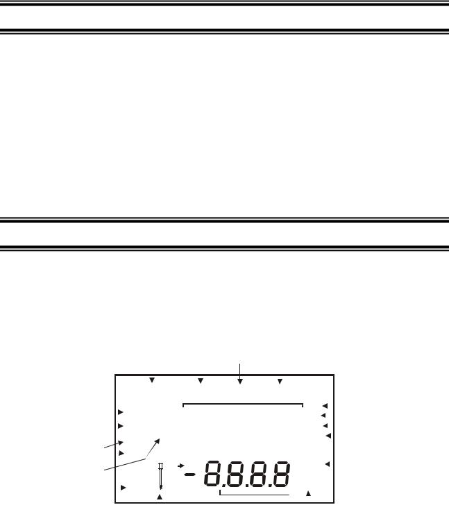
2.1Display
The LCD (Liquid Crystal Display) has an upper and lower display.
The upper display shows the measured conductivity or TDS reading.
The lower display shows the measured temperature.
The display also shows error messages, keypad functions and program functions.
Upper Display
|
|
|
|
|
|
|
|
|
|
|
1 |
|
|
|
2 |
3 |
|
4 |
|
|
|
|
|
|
|
|
|
|
|
|
|
|||||
|
|
|
|
|
|
|
|
|
|
CAL |
|
|
|
|
|
|
|
|
|
|
|
|
|
|
|
|||||||||||
|
|
|
|
SETUP |
|
MEAS |
MEM |
|
|
|
|
|
|
|
|
|
|
|
|
|||||||||||||||||
|
|
|
|
|
|
|
|
|
|
|
|
|
|
|
|
|
|
|
|
|
|
|
|
|
|
mS |
|
|
5 |
|||||||
17 |
|
|
|
READY |
-8.8.8.8 |
|
|
|
|
|||||||||||||||||||||||||||
|
|
|
|
|
||||||||||||||||||||||||||||||||
|
|
|
µS |
|
|
|
6 |
|||||||||||||||||||||||||||||
|
|
|
||||||||||||||||||||||||||||||||||
|
|
|
|
|
|
|||||||||||||||||||||||||||||||
15 |
|
|
|
ON |
|
|
|
ppt |
|
|
|
|
|
|
|
|
||||||||||||||||||||
16 |
|
|
|
HOLD |
|
|
|
|
|
|
|
|
|
|
|
|
|
|
|
|
7 |
|||||||||||||||
|
|
|
|
OFF |
|
|
|
|
K = |
|
|
|
|
|
|
|
|
|
ppm |
|
|
8 |
||||||||||||||
|
|
|
|
|
|
|
|
|
|
|
|
|
|
|
|
|
|
OC OF |
|
|
|
10 |
||||||||||||||
14 |
|
|
|
|
|
|
|
|
|
|
|
|
|
|
|
|
|
ERR |
|
|
|
|
|
|
|
|
||||||||||
|
|
|
|
|
|
|
|
|
|
|
|
|
|
|
|
|
|
|
|
|
|
|
|
ATC |
|
|
|
|
|
|
|
|
||||
13 |
|
|
|
|
|
|
|
|
|
|
|
|
|
|
|
|
|
|
|
|
|
|
|
|
|
|
|
|
|
|
|
|
||||
|
|
|
|
|
|
|
|
|
|
|
|
|
|
|
|
|
|
|
|
|
|
|
|
|
|
|
|
|
|
|
|
|||||
|
|
|
|
|
|
|
|
|
|
|
|
|
|
|
|
|
11 |
|
|
|
|
|
|
|
|
|
|
|
|
|
|
|
|
|
|
|
|
|
|
|
|
|
|
|
|
|
|
|
|
|
|
|
|
|
|
|
|
|
|
|
|
|
|
|
|
|
|
|
|
|
|
||
|
|
|
|
|
|
|
|
|
|
|
|
|
|
|
|
|
|
|
|
|
|
|
|
|
|
|
|
|
|
|
|
|
||||
|
|
|
|
|
|
|
|
|
|
|
|
12 |
|
|
|
Lower Display |
|
9 |
|
|
|
|
|
|
|
|
|
|||||||||
1. SETup mode indicator |
|
|
|
|
|
|
|
|
7. parts per thousand indicator (ppt) |
|
|
13. Calibration solution |
||||||||||||||||||||||||
|
|
|
|
|
|
|
|
|
|
|
|
|
|
|
|
|
|
|
|
|
|
|
|
|
|
|
|
|
indicator |
|||||||
2. MEASurement mode indicator |
|
8. parts per million indicator (ppm) |
|
|
14. Cell constant indicator |
|||||||||||||||||||||||||||||||
3. CALibration indicator |
|
|
|
|
|
|
|
|
9. Automatic Temperature Compensation 15. ON / OFF indicator |
|||||||||||||||||||||||||||
|
|
|
|
|
|
|
|
|
|
|
|
|
|
|
|
indicator |
|
|
|
|
|
|
|
|
|
|
|
|
|
|
|
|
|
|||
4. MEMory mode indicator |
|
|
|
|
|
|
|
|
10. Temperature scale indicator (oC oF) |
|
|
16. HOLD indicator |
||||||||||||||||||||||||
5. millisiemens indicator (mS) |
|
11. ERRor indicator |
|
|
|
|
|
|
|
17. READY indicator |
||||||||||||||||||||||||||
6. microsiemens indicator (µS) |
|
12. Probe indicator |
|
|
|
|
|
|
|
|
|
|
|
|
|
|
|
|
|
|||||||||||||||||
1
Instruction Manual |
CON 510 |
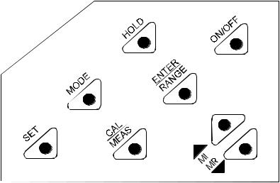
2.2Keypad
The splash-proof membrane tactile keypad allows easy key entry. Each button, when pressed, has a corresponding graphic icon or indicator displayed on LCD. Some buttons have several functions depending on its mode of operation.
Key |
Function |
ON/OFF |
Powers on and shuts off the meter. When you switch on the meter, the meter starts up in the mode |
|
that you last switched off from. For example, if you shut the meter off in TDS measurement mode, |
|
the meter will be in TDS measurement mode when you switch the meter on. |
HOLD |
Freezes the measured reading. To activate, press HOLD while in measurement mode. To release, |
|
press HOLD again. |
MODE |
Selects the measurement parameter. Toggles between conductivity and TDS. |
CAL/MEAS |
Toggles between Calibration and Measurement mode. |
|
NOTE: Temperature calibration is available from conductivity/TDS calibration mode. |
ENTER / |
ENTER function: Press to confirm values in Calibration mode and to confirm selections in SETUP |
RANGE |
mode. |
|
RANGE function: Press to enter manual ranging function. |
|
The MEAS indicator blinks while in manual ranging function. |
|
In Measurement mode: |
MI & MR |
Press MI (memory input) to store values with its corresponding temperature values in the memory. |
|
Press MR (memory recall) to retrieve data from memory (Last-In-First-Out Sequence). |
▼/▲ |
In Calibration mode: |
Press to scroll through calibration values. |
|
|
In SETUP mode: |
|
Press to scroll through the setup subgroup program. |
SETUP |
Takes you into the SETUP mode. This mode lets you customize meter preference and defaults, and |
|
view calibration data and select cell constant. |
2
Instruction Manual |
CON 510 |
3 PREPARATION
3.1Conductivity Electrode Information
The CON510 bench meter is supplied with a Conductivity/TDS electrode (with a sturdy locking 6-pin connector). This Conductivity/TDS electrode (Code No: ECCONSEN91W/ 35608-50) comes with Stainless Steel rings, cell constant of K = 1.0, and a built-in temperature sensor for Automatic Temperature Compensation (ATC). Its specially designed Ultem-body housing has good chemicalresistant properties. It provides fast temperature response and reduces air bubble entrapment, which makes it easy to obtain accurate, stable readings.
The probe materials used which have good chemical durability include:
1.Polyetherimide (Ultem) – protective probe guard
2.Polybutylterphalate (Valox) – sensor housing
3.Stainless Steel (SS 304) – 2 steel bands
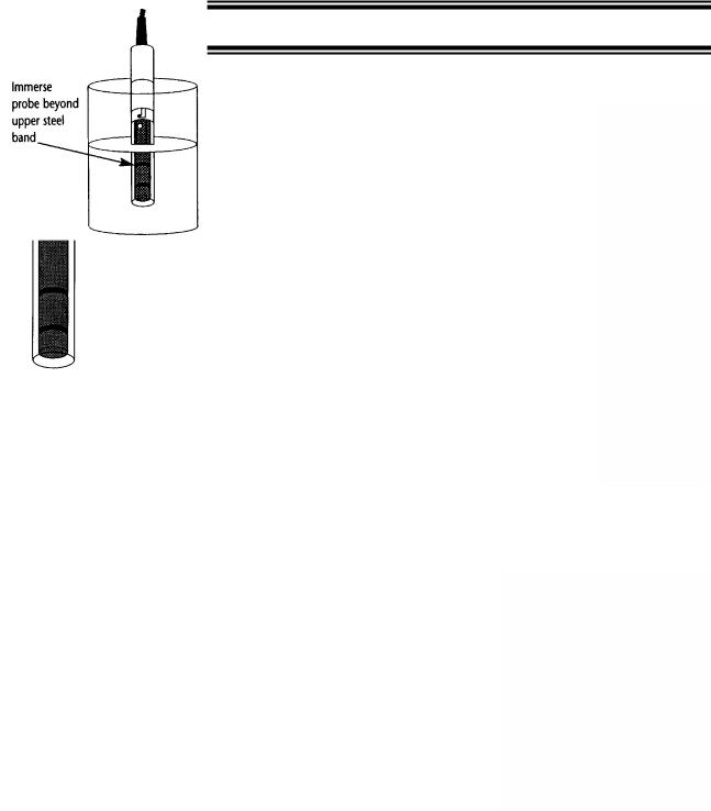
Proper use of probe is essential to ensure that the optimum measurement is taken in a short time. The removable protective plastic probe guard is meant for simple periodic maintenance and it must be kept in tact during measurement and calibration.
Always immerse the probe beyond upper steel band.
NOTE: DO NOT remove the protective probe guard during measurement and calibration as it may affect your readings.
NOTE: We recommend that you do not submerge the probe above the protective probe guard. You can submerge the cable for brief periods of time, but not continuously.
See Section 8 for “Probe Care and Maintenance” information.
3.2Connecting the Probe to the Meter
1.Align the notch and 6 pins on the meter with the holes in the 6-pin connector. Push down and turn the locking ring clockwise to lock into place.
2.To remove probe, turn the locking ring counterclockwise on probe connector until it is free. Pull probe gently away from the meter.
CAUTION: DO NOT pull on the probe cord or the probe wires might disconnect.
NOTE: Keep connectors clean. Do not touch connector with soiled hands.
3.3Connecting the AC/DC Adapter
Slide the AC/DC adapter jack into the socket marked DC of the meter until it is firmly seated. Ensure that the power to the AC/DC adapter is switched off. For AC/DC adapter always ensure that main voltage matches that of the adapter. AC/DC adapters used should have the following specifications or settings. Output: - Voltage: 9 VDC Current: 500 mA.
NOTE: Ensure that the input main voltage (110/220 V) matches your adapter requirements before connection.
3
Instruction Manual |
CON 510 |
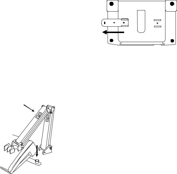
3.4Connecting the Electrode Holder
The integral electrode holder serves as a handy holder for a few electrodes or a separate temperature probe during measurement or when not in use.
This bench meter’s base plate has a side metal bar to which you can attach an integral swivel electrode holder. You can mount the electrode holder on either right or left side of the meter.
To position the electrode arm:
Use a Phillips screwdriver to remove the screw holding the electrode holder. Slide the side metal bar until the second screw slot lines up with the original screw hole. Use the screw removed earlier to secure the electrode holder into position. Note the side metal bar is reversible. If desired, remove screw holding electrode holder base and slide out of brackets, slide base into brackets on opposite side, and tighten screw.
Body of
Electrode
Holder
 Base of
Electrode
Holder
Side Metal Bar
To install the electrode arm to the meter:
To mount the electrode arm into the metal rod on the side bar, align the slot with the metal rod and base of electrode arm. Push it downwards until it fully sits into position. Avoid using excessive force when fixing or removing. The electrode arm is ready for use.
NOTE: Move the base of the electrode holder if you wish to swing the electrode holder. To prevent the meter from toppling over causing accidental spills, DO NOT swing the body of the electrode holder.
4
Instruction Manual |
CON 510 |
4 CALIBRATION
4.1Important Information on Meter Calibration
The CON 510 bench meter allows you to perform automatic calibration (only for Conductivity mode) or manual calibration (applicable to both Conductivity/TDS mode). The meter can calibrate either single point or multi-point up to 5 calibration points (manual mode) with a maximum of 1 point in each measurement range. Use single-point automatic calibration when calibrating using Conductivity standard calibration solutions (as mentioned in Section 4.6) as it suffices.
When calibrating using uncommon or non-standard Conductivity/TDS calibration solutions which are freshly prepared, use the manual calibration option as it allows you to manually set to the desired value to match the standards being used. However if you are measuring sample values in more than one range, it is recommended to calibrate each of the ranges which you are measuring to ensure best meter accuracy.
•If you are measuring in ranges near to or greater than 20 mS (10 ppt if TDS factor is set to 0.5), or near to or lower than 100 µS (50 ppm), calibrate the meter at least once a week to get specified ±1% Full Scale accuracy.
•If you are measuring in the mid-ranges and you washed the probe in de-ionized water and stored it dry, calibrate the meter at least once a month.
•If you take measurements at extreme temperatures, calibrate the meter at least once a week.
For best results, select a standard value close to the sample value you are measuring. Alternatively, use a calibration solution value that is approximately 2/3 the Full-Scale value of the measurement range you plan to use. For example, in the 0 to 2000 µS/cm conductivity range, a 1413 µS/cm solution is a good solution for calibration.
The following table lists all the corresponding conductivity and TDS ranges. You should calibrate each range using a suitable standards solution that falls between the values in the “recommended calibration solution range” column.
Range |
Conductivity |
Recommended |
TDS |
Recommended |
|||
Range |
Calibration Solution |
Range |
Calibration Solution |
||||
Indicator |
|||||||
|
|
Range |
|
|
Range |
||
|
|
|
|
|
|||
|
|
|
|
|
|
|
|
r 1 |
0 – 20.00 µS/cm |
6.00 |
- 17.00 µS/cm |
0 – 10.00 ppm |
3.00 |
- 8.50 ppm |
|
r 2 |
0 – 200.0 µS/cm |
60.0 |
- 170.0 µS/cm |
0 – 100.0 ppm |
30.0 |
- 85.0 ppm |
|
|
|
|
|
|
|
|
|
r 3 |
0 – 2000 µS/cm |
600 |
- 1700 µS/cm |
0 - 1000 ppm |
300 |
- 850 ppm |
|
r 4 |
0 – 20.00 mS/cm |
6.00 - 17.00 mS/cm |
0 – 10.00 ppt |
3.00 - 8.50 ppt |
|||
|
|
|
|
|
|||
r 5 |
0 – 200.0 mS/cm |
60.0 - 170.0 mS/cm |
0 - 100 ppt |
30.0 – 85.0 ppt |
|||
|
|
|
|
|
|
|
|
When you recalibrate your meter, old calibration values are replaced on that specific measurement range. For example, if you previously calibrated the meter at 1413 µS/cm in the 0 - 2000 µS/cm range and you recalibrate at 1500 µS/cm (in the same range of 0 - 2000 µS/cm), the meter will replace old calibration data (1413 µS/cm) in that range if the meter is in the multi-point calibration mode and the meter will retain all calibration data in other ranges. Or else, the calibration data replaces with new data for all ranges (in single-point calibration mode).
To view calibrated solutions and its corresponding cell constants at respective range, see SETUP main-menus P1.0 and P2.0.
To completely recalibrate your meter, or when you use a replacement probe, it is best to clear all the calibration data in the meter’s memory. To erase all the old conductivity and TDS calibration data completely from memory, see SETUP main-menu P7.0.
Temperature Coefficient: This meter is factory set to a temperature coefficient of 2.1 % per °C. For most applications this will provide good results. See SETUP sub-menu P4.1 to set the temperature coefficient to different value. See also Addendum 2, “Calculating Temperature Coefficients” to determine the appropriate temperature coefficient for your solution.
5
Instruction Manual |
CON 510 |
Normalization Temperature: The factory default value for normalization temperature is 25 °C. If you need to normalize to a value other than 25 °C, see SETUP sub-menu P4.2.
4.2Preparing the Meter for Calibration
Before starting calibration, make sure you are in the correct measurement mode. Otherwise press MODE key to toggle between measurement modes. When you switch on the meter, it starts up in the last unit of measure when you last shut off the meter.
DO NOT reuse calibration solutions after each calibration has been performed. Contaminants in the solution can affect the calibration, and eventually the accuracy of the measurements. Use fresh calibration solution each time you calibrate your meter. Always remember to rinse thoroughly with de-ionized water or a rinse solution after each calibration to prevent any carry-over.
NOTE: When entering calibration mode, the meter will display the uncalibrated value.
To abort or exit from any calibration mode or SETUP options without confirming any set values, DO NOT press the ENTER key. Press CAL/MEAS instead. This will retain the meter’s old calibration data in the specific measurement range or previous SETUP options.
4.3Calibration with Conductivity Standards and TDS factor
The concentration of salts dissolved in solution increases the conductivity of that solution. This relationship varies from salt to salt and is roughly linear over a given range for a given salt. The TDS conversion factor is the number used by the meter to convert from conductivity to TDS. Default is 0.50; allowed window is 0.40 to 1.00.
Instead of calibrating for TDS directly, you can calibrate the CON 510 bench meter by:
1.calibrating to conductivity standards and then
2.entering the appropriate TDS conversion factor into the meter.
To determine the conductivity to TDS conversion factor for your solution:
Addendum 2 lists some commonly used conversion factors.
Addendum 3 describes how to calculate the TDS conversion factor for other solutions.
Enter the TDS conversion factor into your meter as described under SETUP sub-menu P3.4.
4.4Calibration for TDS Standards Directly
The factory default setting for TDS conversion factor is 0.50. If your solution has a different TDS factor, you can improve the calibration accuracy by setting the correct TDS factor (0.40 to 1.00) prior to calibration in SETUP sub-menu P3.4.
4.5Selection of Automatic or Manual Calibration
This meter is capable of performing either automatic for Conductivity measurement mode or manual calibration method for both Conductivity and TDS measurement modes. In the automatic calibration mode, the meter automatically detects and verifies the appropriate known calibration standards solutions being calibrated before accepting these particular calibration standards as one of its calibration values in a specific measurement range. This automatic calibration mode frees you from cumbersome calibration procedure. While in the manual calibration, non-standards calibration values can be used for calibration, in which you can manually input the appropriate values as your desired calibration standards in each specific range.
Proceed to SETUP main-menu P5.0 to select the type of calibration method before performing calibration.
6
Instruction Manual |
CON 510 |
4.6Automatic Calibration (Only for Conductivity)
In the automatic calibration mode, the CON 510 bench meter is capable of accepting either single-point or up to 4 points for multi-point calibration with maximum of 1 point per specific measurement range using known calibration standards values which include: 84 µS/cm (0 – 200.0 µS/cm), 1413 µS/cm (0 – 2000 µS/cm), 12.88 mS/cm (0 – 20.00 mS/cm) and 111.8 mS/cm (0 – 200.0 mS/cm).
NOTE: You need to set your desired option i.e. number of calibration points in the SETUP main-menu P5.0 before performing calibration.
4.6.1Conductivity Automatic Calibration
1.If necessary, press the MODE key to select conductivity mode.
2.Rinse the probe thoroughly with de-ionized water or a rinse solution, then rinse with a small amount of calibration standard.
3.Dip the probe into the calibration standard. Immerse the probe tip beyond the upper steel band. Stir the probe gently to create a homogeneous sample. Allow time for the reading to stabilize.
4.Press CAL/MEAS to enter conductivity calibration mode. The [CAL] indicator will appear in the upper right corner of the display.
5.The lower display will scan and lock the closest set calibration values momentarily. Pressing before the set displayed value being locked will be prompted by an error message and remain in the calibration mode.
6.Wait for [READY] indicator to appear before pressing ENTER key to confirm calibration value. The upper display will show “dOnE” once the calibration is successfully performed. The meter returns to the [MEAS] measurement mode.
7.To abort calibration without confirming, press CAL/MEAS to revert back to measurement mode. No calibration is performed at this stage.
8.To perform the next point calibration in the multi-point calibration, repeat step 1-7 again until all points have been calibrated if necessary.
MODE
MEAS
READY
|
uS |
. |
oC |
ATC |
|
CAL |
|
MEAS |
|
 CAL
CAL
READY
uS
ENTER
RANGE
CAL
MEAS
MEAS
READY
uS

 .
. oC
oC
ATC
7
 Loading...