


E1
www.etoncorp.com
E1
MANUAL
AM/FM/SHORTWAVE/XM READY RADIO
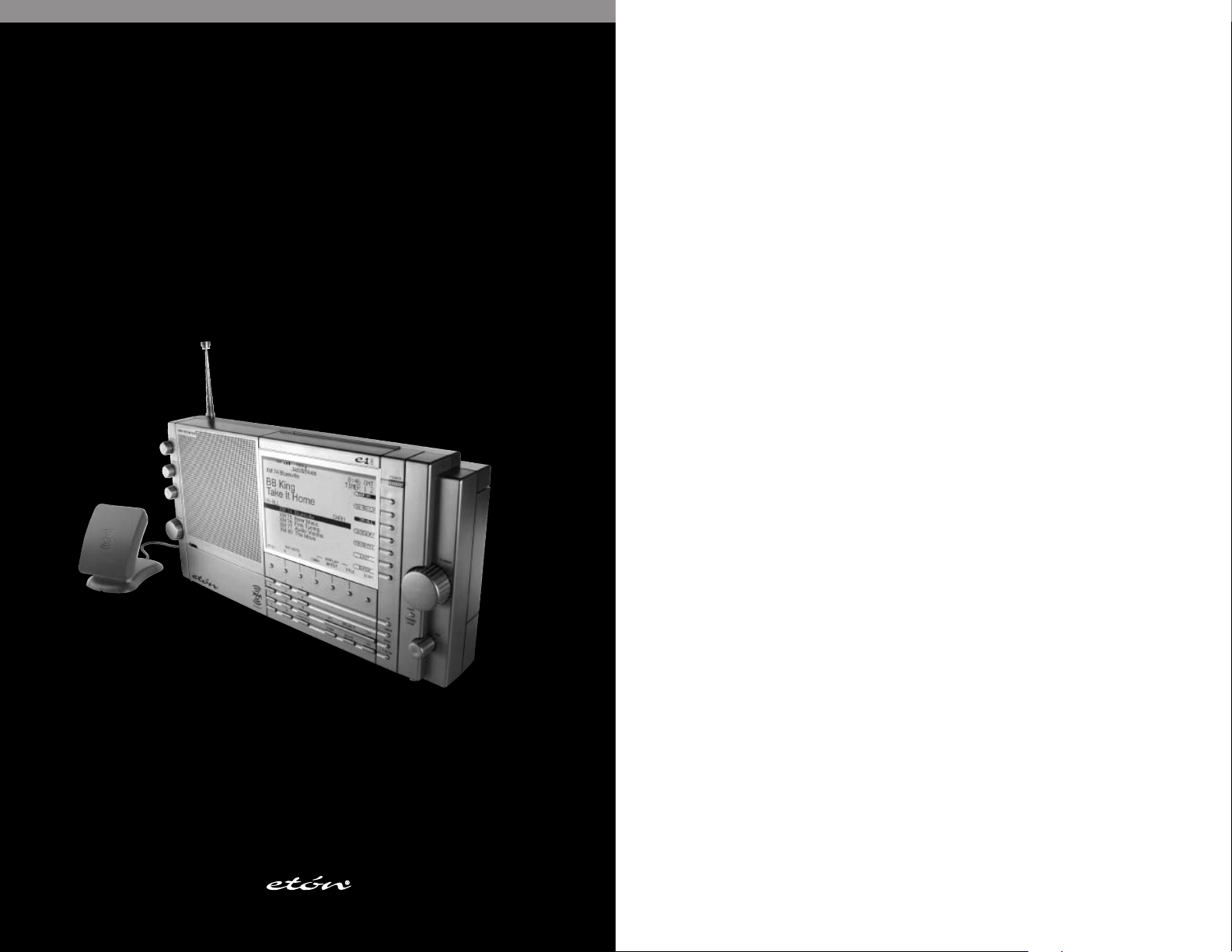
E1 AM/FM/Shortwave/XM Ready Radio
E1 MANUAL
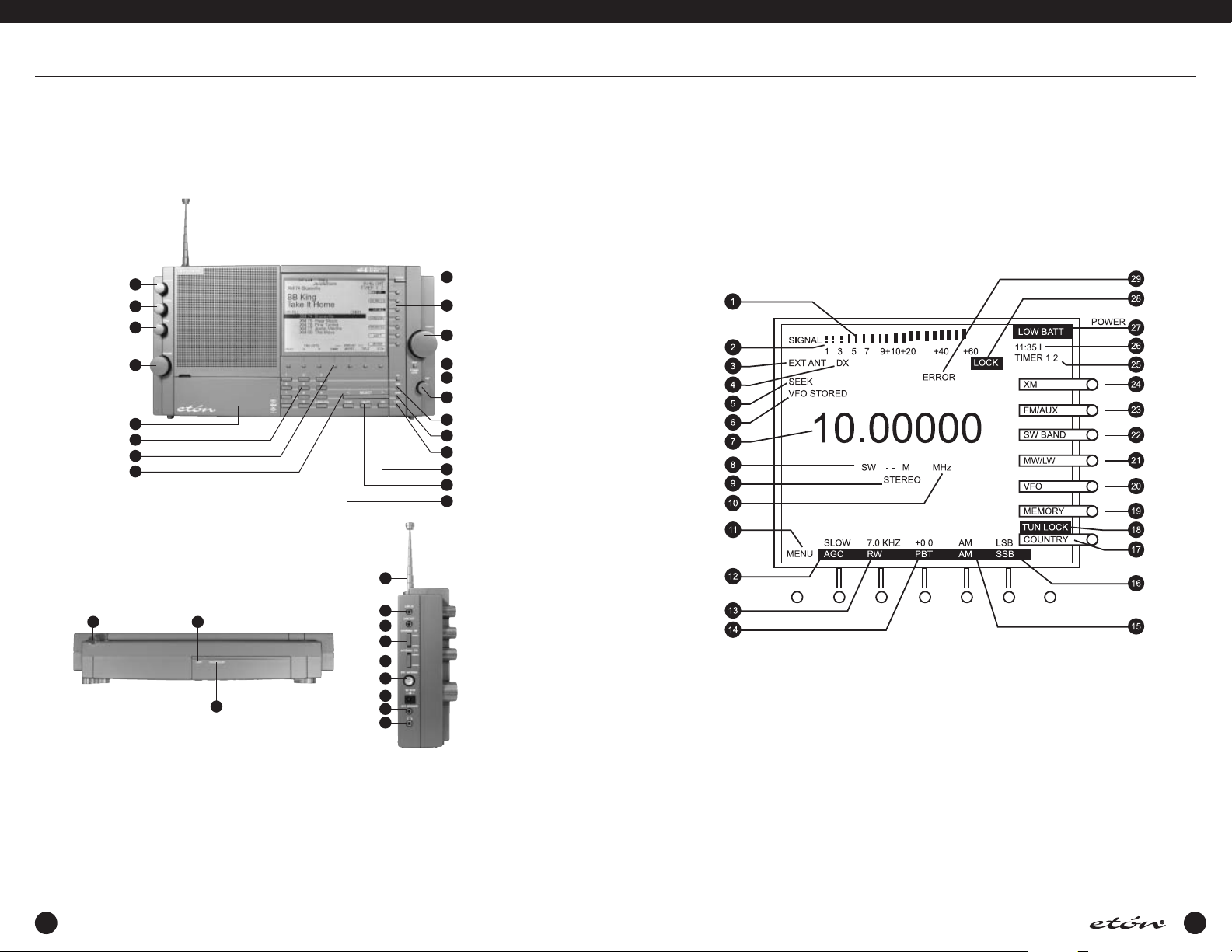
FRONT PANEL DESCRIPTION (See page 13)
1
2
3
4
5
6
7
8
TOP PANEL DESCRIPTION (See page 17)
1
2
3
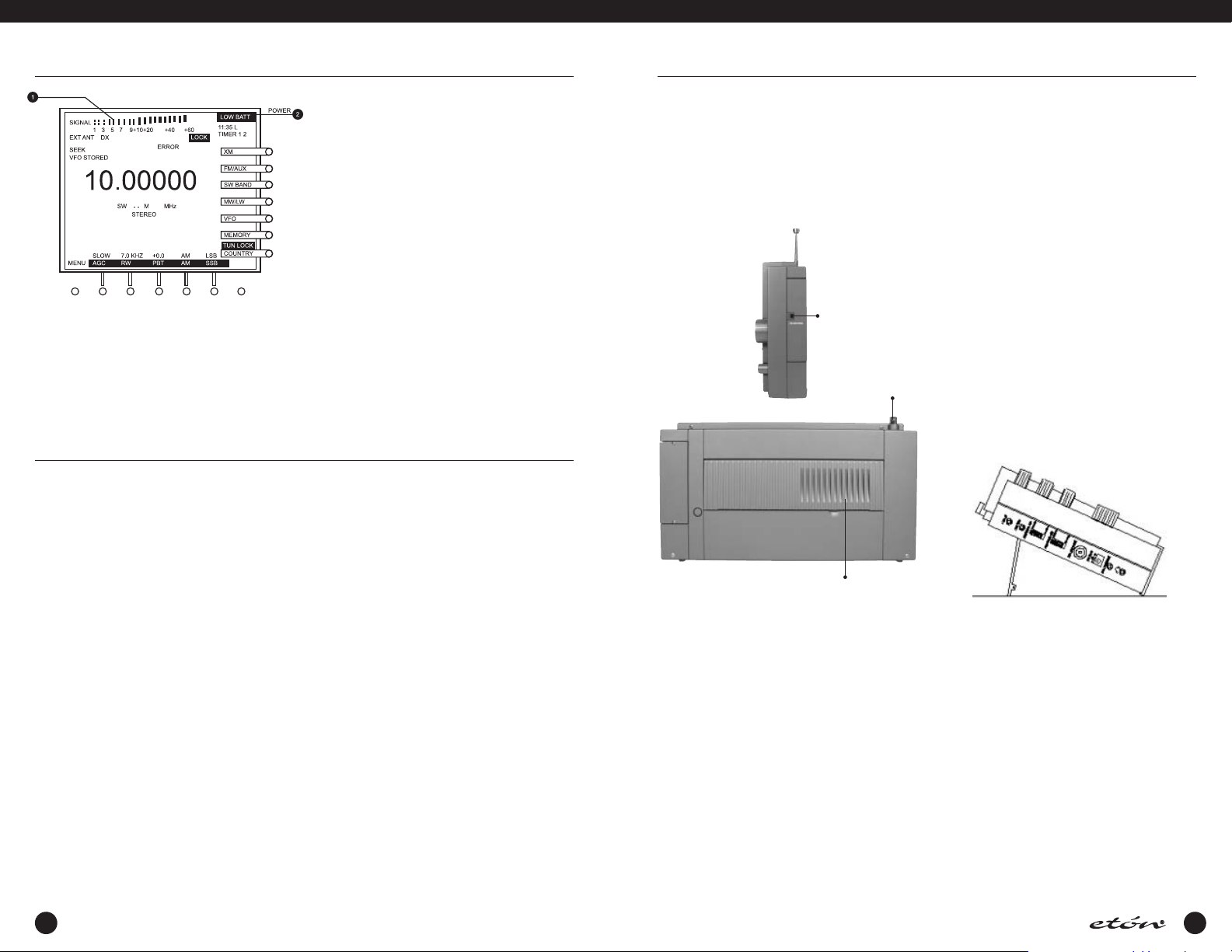
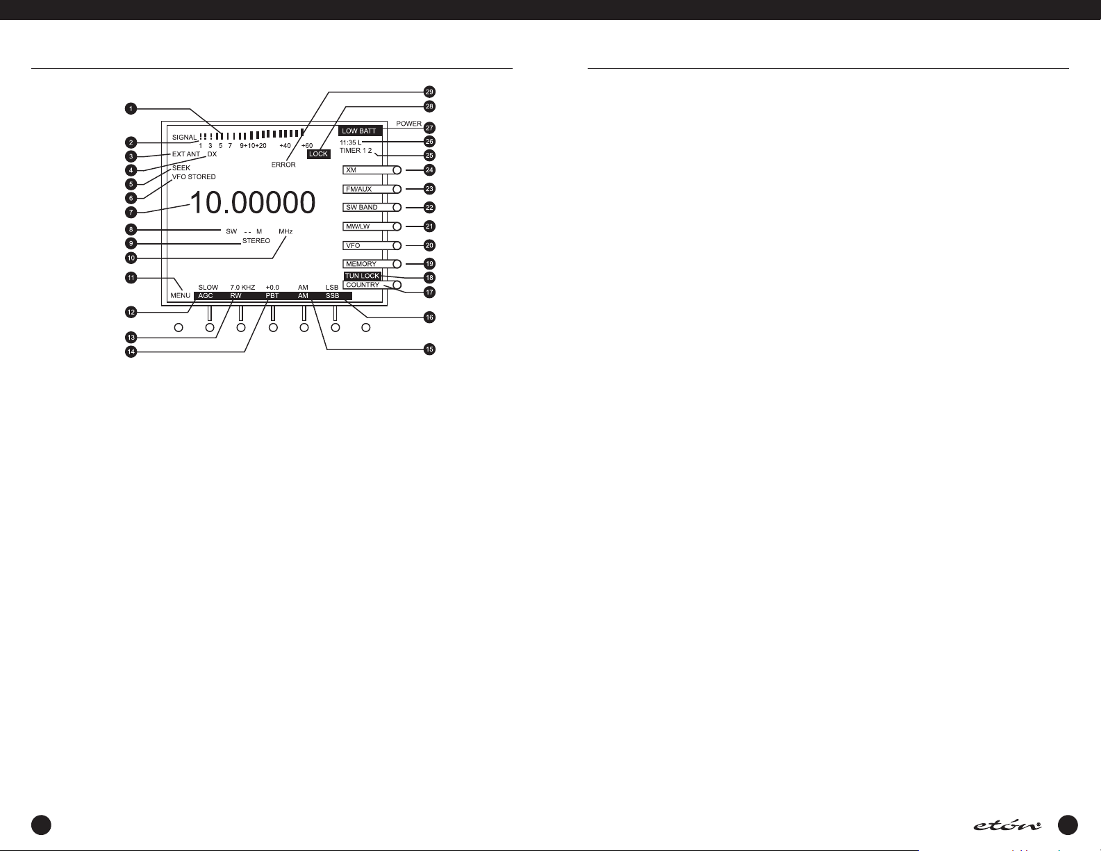
E1 DISPLAY DESCRIPTION (See page 18)
20
19
18
17
16
15
14
13
12
11
10
9
1
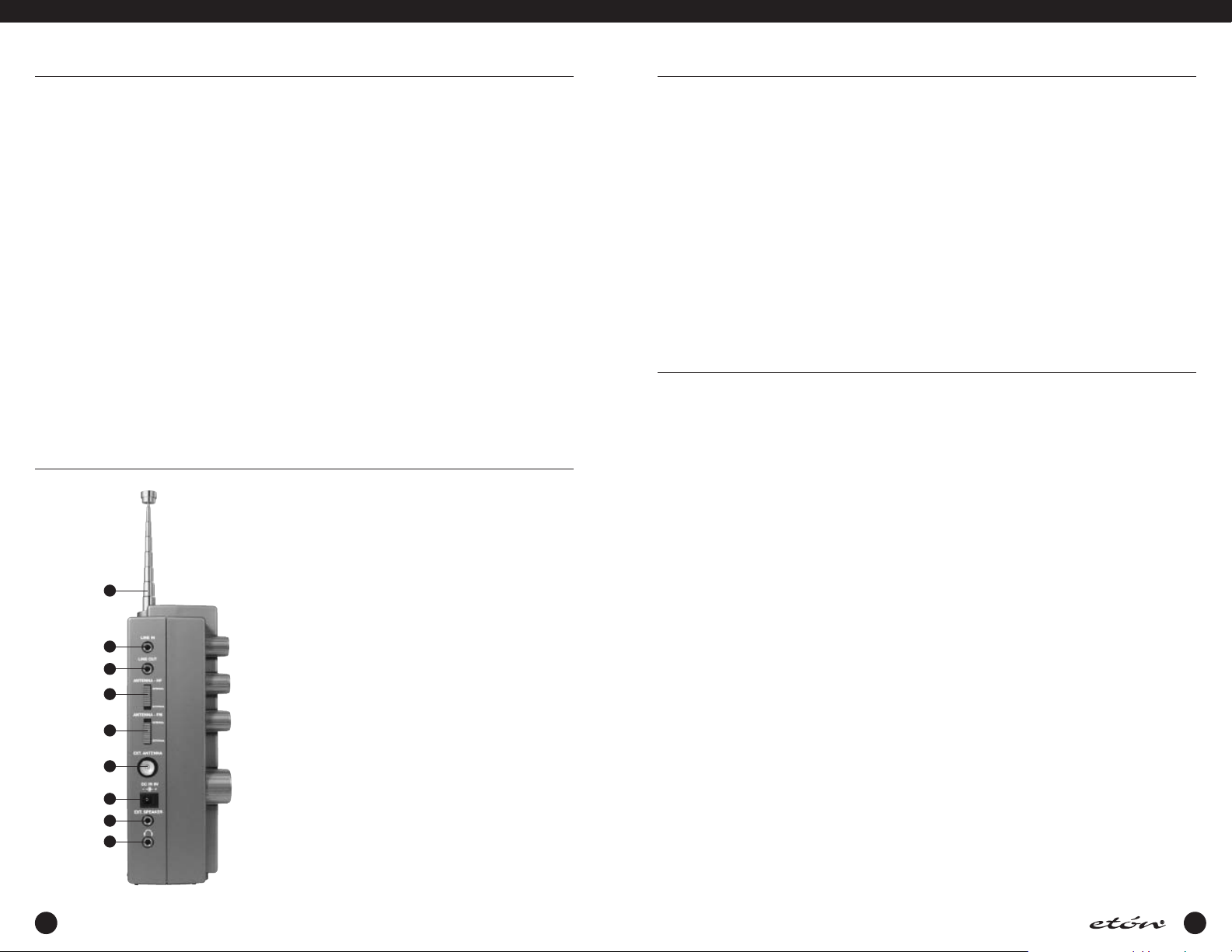
SIDE PANEL
2
3
4
5
6
7
8
9
DESCRIPTION
(See page 20)
2 3
E1 MANUAL
IMPORTANT SAFEGUARDS
An appliance and cart combination should be moved
with care. Quick stops, excessive force and uneven surfaces m ay cause the appliance and cart combination
to overturn.
The lightning flash with arrow head symbol, within an
equilateral triangle, is intended to alert the user to the
presence of uninsulated “dangerous voltage” within
the product’s enclosure that may be of sufficient magnitude to constitute a risk of electric shock to persons.
An exclamation point within an equilateral triangle is
intended to alert the user to the presence of important
operating and maintenance (servicing) instructions in
the literature accompanying the appliance.
WARNING
WARNING: TO REDUCE THE RISK OF FIRE OR ELECTRIC SHOCK, DO NOT EXPOSE THE APPLIANCE TO RAIN OR MOISTURE.DO NOT OPEN
THE CABINET, REFER SERVICING TO QUALIFIED PERSONNEL ONLY.
CAUTION
TO PREVENT ELECTRIC SHOCK, DO NOT USE THE THREE WIRE CORD W ITH AN EXTENSION CORD RECEPTACLE OR OTHER OUTLET
UNLESS THE BLADES CAN BE FULLY INSERTED TO PREVENT BLADE EXPOSURE.
ATTENTION
POUR PREVENIR LES CHOCS ELECTRIQUES, NE PAS UTILISER CETTE FICHE POLARISEE AVEC UN PROLONGATEUR, UNE PRISE DE
COURANT OU UNE AUTRE SORTIE DE COURANT,SAUF S I LES LAMES PEUVENT ETRE INSEREES A FOND SANS EN LAISSER AUCUNE PARTIE A DECOUVERT.
IMPORTANT SAFEGUARDS continued
connection a la terre ne manque pas.
13. Power-Cord Protection - Power supply cords should be routed
so that they are not likely to be walked on or pinched by
items placed upon or against them, paying particular attention to cords at plugs, convenience receptacles, and the point
where they exit from the product.
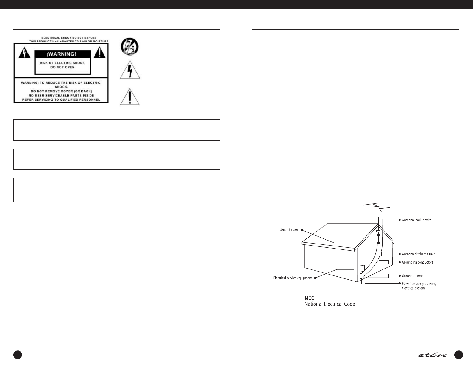
14. Outdoor Antenna Grounding - If an outside antenna or cable
system is connected to the product, be sure the antenna or
cable system is grounded so as to provide some protection
against voltage surges and built-up static charges.Article 810
of the National Electrical Code,ANSI/NFPA 70, provides information with regard to proper grounding of the m ast and
supporting structure, grounding of the leadin wire to an
antenna discharge unit, size of grounding conductors, location of antenna-discharge unit, connection to grounding electrodes, and requirements for the grounding electrode. See figure A .
15. Lightning - For added protection for this product during a
lightning storm, or when it is left unattended and unused for
long periods of time, unplug the AC adapter from the wall
outlet and disconnect the antenna or cable system. This will
prevent damage to the product due to lightning and powerline surges.
16. Power Lines - An outside antenna system should not be located in the vicinity of overhead power lines, other electric light
or power circuits, where it can fall into such power lines or
circuits.W hen installing an outside antenna system, extreme
care should be taken to keep from touching such power lines
or circuits as contact with them m ay be fatal.
17. Overloading - Do not overload wall outlets and extension
cords or integral convenience receptacles as this can result in
a risk of fire or electric shock.
18. Object and Liquid Entry - Never push objects of any kind into
this product through openings as they may touch dangerous
voltage points or short-out parts that could result in fire or
electric shock. Never spill liquid of any kind on the product.
19. Servicing - Do not attempt to service this product yourself as
opening or removing covers may expose you to dangerous
voltage or other hazards. Refer all servicing to qualified service personnel.
20. Damage Requiring Service - Unplug this product from the wall
outlet and refer servicing to qualified service personnel under
the following conditions:
a. When the AC adapter cord or plug is damaged.
b. If liquid has been spilled, or objects have fallen into the
product.
c. If the AC adapter has been exposed to rain or water.
d. It the product does not operate normally by following the
operating instructions.Adjust only those controls that are
covered by the operating instructions.An improper adjust-
ment may result in damage and will often require exten-
sive work by a qualified technician to res tore the product
to its normal operation.
e. If the product has been dropped or the cabinet has been
damaged in any way and
f.When the product exhibits a distinct change in perfor-
mance-this indicates a need for service.
21. Replacement Parts - W hen replacement parts are required, be
sure the service technician has used replacement parts specified by the manufacturer or have the same characteristics as
the original parts. Unauthorized substitutes may result in fire,
electric shock or other hazards.
22. Safety Check - Upon completion of any service or repairs to
this product, ask the service technician to perform safety
checks to determine that the product is in proper operating
condition.
23. Wall or Ceiling Mounting - The product should be mounted to
a wall or ceiling only as recommended by the manufacturer.
24. Heat - The product should be situated away from heat
sources such as radiators, heat registers, stoves, or other
products (including amplifiers) that product heat.
1. Read Instructions - All the safety and operating instructions
should be read before the appliance is operated.
2. Retain Instructions - The safety and operating instructions
should be retained for future reference.
3. Heed Warnings - All warnings on the appliance should be
adhered to.
4. Follow Instructions - All operating and use instructions should
be followed.
5. Cleaning - Unplug this appliance from the wall outlet before
cleaning. Do not use liquid cleaners or aerosol cleansers. Use
a dam p cloth for cleaning.
6. Attachments - Do not use attachments that are not recommended by the manufacturer or they may cause hazards.
7. Water and Moisture - Do not use this product near water-for
example, near a bathtub, wash bowl, kitchen sink, laundry
tub; in a wet basement; or near a swimming pool-and the
like.
8. Accessories - Do not place this product on an unstable cart,
stand, tripod, bracket, or table.The product may fall, causing
serious injury to a child or adult, and serious damage to the
product. Any mounting of the product should follow the manufacturer’s instructions,and should use a mounting accessory
recommended by the manufacturer.
9. A product and cart combination should be moved with care.
Quick stops, excessive force, and uneven surfaces may cause
the product and cart combination to overturn.
10. Ventilation - S lots and openings in the cabinet are provided
for ventilation and to ensure reliable operation of the product
and to protect it from overheating, and these openings must
not be blocked or covered.The openings should never be
4
blocked or by placing the product on a bed, sofa, rug, or similar surface.This product should not be placed in a built-in
installation such as a bookcase or rack unless proper ventilation is provided or the manufacturer’s instructions have been
adhered to. KEEP CURTAINS AND OTHER FLAMMABLE MATERIALS OUT OF DIRECT CONTACT WITH THE AC ADAPTER.
11. Power Sources - This product should be operated only from
the type of power source indicated on the marking label of
the supplied AC Adapter. If you are not sure of the type of
power supplied to your home, consult your appliance dealer
or local power company. For products intended to operate
from battery power,or other sources, refer to the operating
instructions.
12. Grounding or Polarization - This product may be equipped
with a polarized alternating-current line plug (a plug hav ing
one blade wider than the other). This plug will fit into the
power outlet only one way.This is a safety feature.If you are
unable to insert the plug fully into the outlet, try reversing the
plug. If the plug should still fail to fit, contact your electrician
to replace your obsolete outlet. Do not defeat the safety purpose of the polarized plug. Alternate W arnings- If this product is equipped with a three-wire grounding-type plug, a plug
having a third (grounding) pin, the plug will only fit into a
grounding-type power outlet. This is a safety feature. If you
are unable to insert the plug into the outlet, contact your
electrician to replace your obsolete outlet. Do not defeat the
safety purpose of the grounding-type plug.
12a. M ise à la terre ou Polarisation - Cet appareil est équipé
avec un cordon d’alimentation à trois fils.Il est a brancher sur
une prise ayant un connecteur a la terre.Assurez-vous que la
5

2 TABLE OF CONTENTS
THANK YOU FOR PURCHASING THE etón E1 RECEIVER. THIS RECEIVER HAS BEEN DESIGNED AND MANUFACTURED TO HIGH QUALITY STANDARDS,AND WILL PROVIDE RELIABLE OPERATION FOR MANY YEARS. PLEASE CAREFULLY READ THE OWNER’S MANUAL IN
ORDER TO TAKE ADVANTAGE OF THE MANY INTERESTING FEATURES THAT WILL PROVIDE ENJOYABLE LISTENING TO RADIO BROADCASTS AROUND THE WORLD.
E1 MANUAL
IMPORTANT SAFEGUARDS p.4
TABLE OF CONTENTS p.6
GENERAL DESCRIPTION p.8
POWER SUPPLY p.8
• AC ADAPTER and EXTERNAL DC POWERING
• BATTERY INSTALLATION
• BATTERY OPERATION
• BATTERY CONDITION
INSTALLATION p.10
• UNPACKING
• LOCATION
• FIXED INSTALLATION
• PORTABLE OPERATION
• ANTENNA REQUIREMENTS
• VIEWING ANGLE
• INSTALLATION DIAGRAM
E1 FRONT PANEL DESCRIPTION p.13
TOP PANEL DESCRIPTION p.17
E1 DISPLAY DESCRIPTION p.18
SIDE PANEL DESCRIPTION p.20
GETTING STARTED p.21
• GENERAL OPERATING INFORMATION
• FIRST STEPS
• DIRECT FREQUENCY ENTRY
• SHORTWAVE ‘METER' BAND DESIGNATOR ENTRY
• FREQUENCY RESOLUTION
• FRONT PANEL LOCK (UNLOCK)
• AM SYNCHRONOUS OPERATION
• SSB OPERATION
• PASSBAND TUNING
• FM OPERATION
• AGC OPERATION
• BEEP TONES
MEMORY FUNCTIONS p.26
• MEMORY DESCRIPTION
• THE MEMORY DISPLAY
• STORING A MEMORY CHANNEL
• RECALLING A MEMORY CHANNEL
• DELETING A MEMORY CHANNEL
COUNTRY FUNCTIONS p.28
• COUNTRY DESCRIPTION
• THE COUNTRY DISPLAY
• STORING A COUNTRY CHANNEL
• RECALLING A COUNTRY CHANNEL
• DELETING A COUNTRY CHANNEL
• CHANGING OR ADDING COUNTRY NAMES
XM OPTION DISPLAY DESCRIPTION p.31
INTRODUCTION TO XM SATELLITE RADIO p.34
• GETTING STARTED IN XM RADIO
• XM DISPLAY OPTIONS
• THE XM ‘LAST’ SOFTKEY
• XM FAVORITES
E1 MENUS p.38
• MAIN MENU
• RADIO SETTINGS
• AUDIO SETTINGS
• SET CLOCKS
• CLOCK MODES
• TIMERS
• XM
• TIMER 1 ENABLE / DISABLE
• TIMER 2 ENABLE / DISABLE
• LOCAL / GMT TIME SELECT
SEEK FUNCTION p.50
• DESCRIPTION
• VFO MODE
• MEMORY & COUNTRY MODE
• XM SATELLITE RADIO MODE
T.SCAN FUNCTION p.51
• DESCRIPTION
• MARKING CHANNELS FOR T.SCAN
• UNMARKING T.SCAN CHANNELS
• SELECTING THE SCAN STOP METHOD
• INITIATING AND STOPPING THE T.SCAN
CLOCK AND TIMER FUNCTIONS p.52
• TIME DISPLAY
• SETTING 24 HOUR CLOCKS AUTOMATICALLY
• SETTING THE 24 HOUR CLOCKS MANUALLY
• TIMER OPERATION
• SETTING TIMER ON/OFF TIMES
• SETTING A W AKE OR SLEEP TIMER
• SETTING TIMER MEMORY CHANNELS
• ENABLING/DISABLING TIMER OPERATION
SPECIAL USE FEATURES AND FUNCTIONS p.56
• LOCK ALL ENTRY TO KEYPAD
• BROADCAST BAND TUNING STEP SIZE
• DELETE ALL MEMORY OR COUNTRY CHANNELS
• DELETE ALL MEMORY AND COUNTRY CHANNELS
• DISPLAY LIGHTING
QUICK REFERENCE GUIDE p.59
GLOSSARY OF TERMS p.62
TROUBLESHOOTING p.63
SUGGESTED REFERENCES p.63
WARRANTY REGISTRATION p.64
LIMITED WARRANTY p.64
SERVICE INFORMATION p.64
APPENDIX p.65
• UNDERSTANDING SHORTWAVE BANDS p.65
- WHAT IS SHORTWAVE?
- SOME BASIC RULES OF THUMB
- WHAT ARE BANDS?
- A HELPFUL ANALOGY ABOUT BANDS
- DAY BANDS v s.NIGHT BANDS
- SUNSET AND SUNRISE
- DAYTIME LISTENING
- EVENING/NIGHT LISTENING
- SHORTWAVE DIRECTORY
- SHORTWAVE ANTENNAS
- FULL-SIZED PASSIVE SHORTWAVE ANTENNAS
- ACTIVE SHORTWAVE ANTENNAS
- SHORTWAVE ANTENNAS FOR USE ON BOATS
- LONG-WIRE SHORTWAVE ANTENNAS
- AM ANTENNAS
- FINDING ANTENNAS
- TIME STATIONS
- GETTING STARTED W ITH SINGLE SIDEBAND (SSB)
- WEATHER FAX FREQUENCIES
- MORE INFORMATION ABOUT SSB
- MONTHLY MAGAZINES W ITH SSB RELATED INFO
- TIME STATIONS (not SSB)
• ETON E1 QUICK GUIDE p.70
- INTRODUCTION
- SET-UP INFORMATION
- LISTENING TO XM SATELLITE RADIO
- TUNING-IN FM AND MW STATIONS
- USING DIRECT FREQUENCY ENTRY
- USING THE SEEK FEATURE
- LISTENING TO SHORTWAVE STATIONS
- CHOOSING THE BEST SHORTWAVE BAND
- GETTING INTO A SHORTWAVE BAND
- TUNING AROUND IN A SHORTWAVE BAND
- STORING FREQUENCIES INTO MEMORY
- ACCESSING W HAT YOU HAVE STORED INTO MEMORY
- DELETING THE CONTENTS OF A MEMORY
- SETTING THE CLOCK TO YOUR LOCAL TIME
- SETTING THE DISPLAY FOR LOCAL OR GMT TIME
- SETTING THE TIMER AS AN ALARM CLOCK
- USING TIMER 1 AS A W AKE-UP TIMER
- USING TIMER 2 AS A SLEEP TIMER
- TO ENABLE OR DISABLE THE TIMERS
SPECIFICATIONS p.74
BLOCK DIAGRAM p.76
6 7
E1 MANUAL
GENERAL DESCRIPTION
The etón E1 is a microprocessor controlled, synthesized,
world band receiver with continuous coverage capability
from 100 kHz through 30 MHz and from 76 MHz
through 108 MHz which includes the AM broadcast and
shortwave bands as well as the FM broadcast band.The
E1 also receives XM Satellite Radio (subscription
required), when the optional remote XM digital antenna
is connected.
The receiver offers excellent sensitivity,selectivity,
dynamic range, and features that permit easy tuning of
desired stations. Conveniently located front panel controls allow for rapid operator programming and ease of
use.The units can be operated from either the supplied
AC ADAPTER,an external 7 to 14 VDC source, or from
four "D" cell batteries (not supplied) for portable operation. A low battery voltage indication is displayed when
that condition exists.
Three electronically switched IF filters are provided to
provide optimum interference rejection for each mode.
The front panel dot matrix liquid crystal display provides
feedback of the current status of the receiver. The seven
digit frequency display provides resolution to 10 Hz in
the AM broadcast and Shortwave bands. Resolution to
20 kHz is displayed in the FM broadcast band.
Backlighting of the display is selectable by a “LIGHT”
key on top of the cabinet.To prolong battery life with
internal battery operation, the backlighting automatically
turns off after a short delay following a function change
or retuning of the receiver unless it is specifically locked
in the ON mode.
When the receiver is turned off, the display provides
either the Local time or Greenwich Mean time (GMT),
selectable in either the off or on state by the user.
Reception modes include Single Sideband (LSB & USB)
and AM in the Shortwave, MW (AM broadcast) and LW
POWER SUPPLY
AC ADAPTER and EXTERNAL DC POWERING
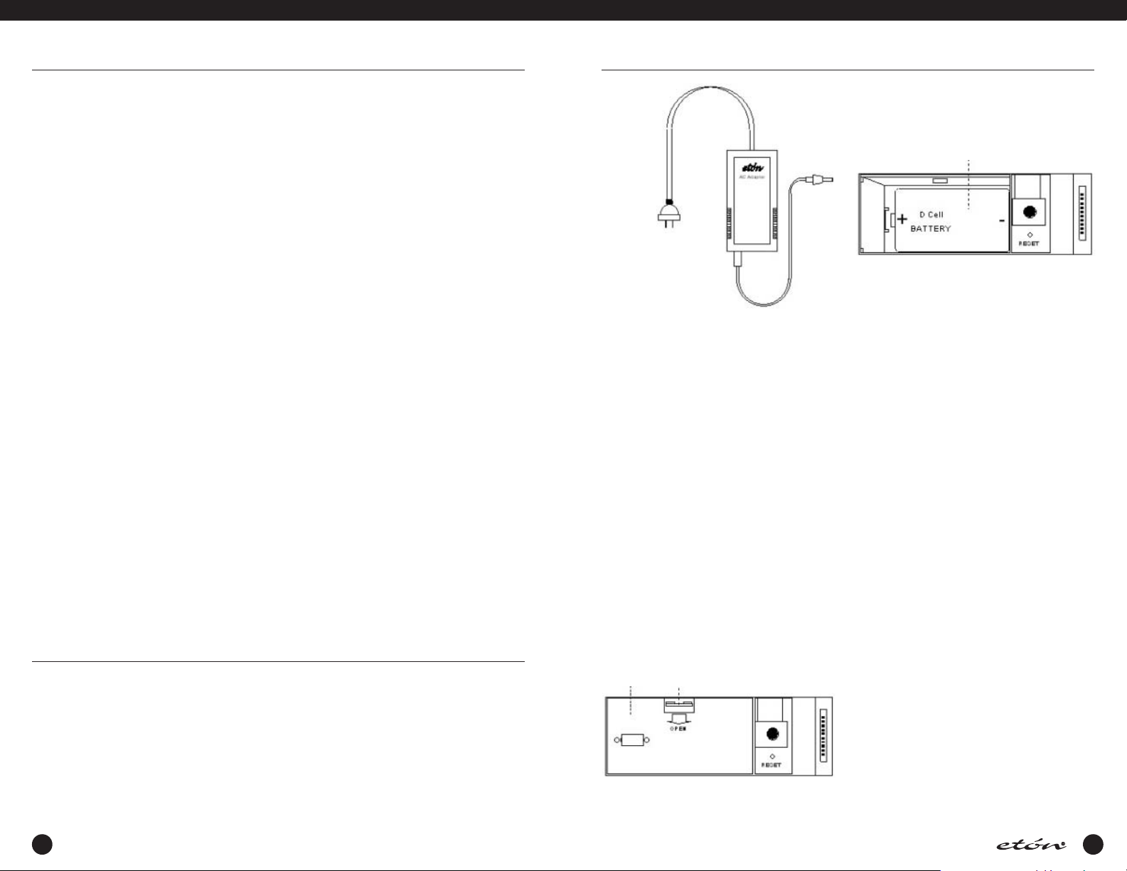
The etón E1 receiver is supplied with an AC ADAPTER.
The AC ADAPTER is designed to be plugged into a wall
outlet that supplies AC power, or another source of external filtered DC power between 7 and 12 VDC may be
used.
Connect the output connector of the AC adapter, or other
power source, to the 9 VDC, 1 amp connector on the side
of the receiver.
bands. For the LW, Shortwave and MW bands, a selectable sideband synchronous detector (SYNC) allows for
enhanced AM reception by eliminating or reducing distortion due to fading signals or a strong adjacent signal.
During FM broadcast use, stereo reception is available
through the use of headphones, or by connecting the
line out jack to an external stereo system.
Other built-in reception aids include selectable slow,
fast, or automatic AGC time constant, scanning of memory channels, either by time or by carrier presence, passband tuning and squelch as well as treble and bass controls.
Two independent, real time clocks provide Local or GMT
time selection. Also provided are a two event timer, a
SLEEP timer, and a SNOOZE mode.
A programmable memory area allows for 1700 independent receiver set up memories.The first 500 of these
memory channels allow names to be attached to the
frequencies and modes stored. The remaining 1200
memory channels allow frequencies to be stored by
country.There are 111 country names factory stored in
this bank of memory with 10 memory channels available
per country and 90 memory channels remaining with no
country assigned. These country names can be modified
or added to by the user. These memories do not require
battery backup and are thus unaffected by power interruptions.All parameters associated with a particular
memory channel are stored including the frequency,
mode, bandwidth,passband tuning setting, fast, slow,or
automatic AGC and synchronous detector state. These
memory channels may be accessed manually or through
a time scan with each channel monitored for a 5 second
period, or carrier presence.The XM mode includes an
additional 20 memory locations for storing favorite XM
Satellite Radio channels.
If batteries are installed and external power is lost, the
receiver will continue to operate on battery power even
with the DC plug inserted. If this occurs,the receiver will
alert the user with a POWER LOSS indication, and with a
POWER LOSS beep if the POWER LOSS beep feature is
enabled. More details concerning power loss can be
found on page 20, paragraph 27b.
POWER SUPPLY continued
US
Connector
AC ADAPTER
Keep curtains and other flammable materials out of
direct contact with the AC ADAPTER to avoid overheating.
BATTERY INSTALLATION
The etón E1 receiver is also designed to operate from
four "D” cell batteries (not supplied). NOTE: Check the
batteries periodically for leakage. IF UNIT IS TO BE
STORED OR OTHERWISE NOT USED FOR AN EXTENDED
PERIOD OF TIME, REMOVE THE BATTERIES TO PREVENT
CORROSION AND POSSIBLE DAMAGE TO THE RECEIVER. Damage caused by battery acid leakage is not covered under the warranty.
(1) Position the receiver with the front panel towards
you.
(2) Open the battery access door located at the lower
left corner of the front panel. (Shown as #5 in the
front panel drawing.)
(3) Inside you will find an additional door as shown in
the following illustration.
Battery
Access
Panel
Remove this door by pressing down and pulling outward
on the “OPEN” tab.
Simultaneously press
down and pull outward
to open
(4) Insert the first of four “D” sized batteries into the
battery opening with the plus end of the battery to
your left. See the following illustration.
Insert battery with “+” end to the
left, and slide battery to the right
(5) Slide the battery to the right and continue in this
manner until all four batteries are installed. Replace
the inner door and close the outer door.
BATTERY OPERATION
The etón E1 receiver does not rely on the batteries for
retention of memory channels. However, to insure that
clocks are maintained following the loss of AC power
and battery removal, the receiver must first be connected to a source of AC power or have batteries installed.
Clock settings are maintained for a time period of
approximately 10 minutes after all power is removed.
New batteries should be installed before this time period elapses or clock settings will be lost.
8
9
E1 MANUAL
POWER SUPPLY continued
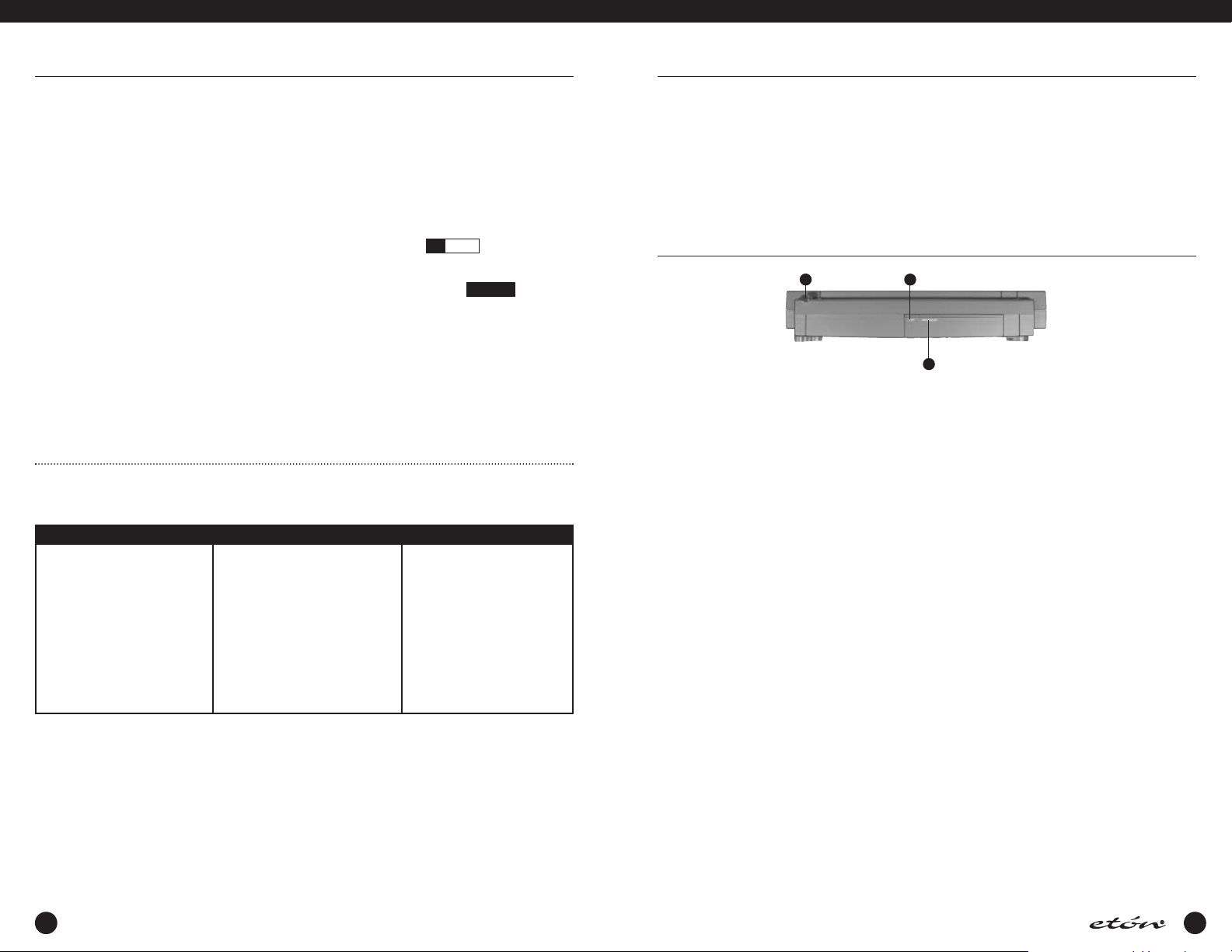
BATTERY CONDITION
Battery condition can be observed when the unit is
turned on or if the ‘LIGHT’ button is pressed if no AC
ADAPTER is connected to the receiver. W hen the
POWER key is pressed, or when the ‘LIGHT’ button is
pressed, a screen will be observed similar to the following illustration during the first two seconds after depres-
INSTALLATION
UNPACKING
Carefully remove the etón E1 receiver and included AC
ADAPTER wall transformer from the shipping carton and
examine them for evidence of damage. If any damage is
noted, immediately contact the transportation company
responsible for delivery, or return the unit to the dealer
from whom it was purchased. Keep the shipping carton
and all packing material for the transportation company
to inspect. The original carton and packing material
should be retained for repackaging should it be necessary
to return the receiver. Inspect the packing material for
any accessories or printed material before storing the
box. Locate the registration card, fill it out, and immediately return it to etón to insure registration and valida-
tion of warranty.
LOCATION
For fixed locations,the etón E1 receiver should be operated from the AC ADAPTER. Keep curtains and other
flammable material away from direct contact with the AC
ADAPTER to avoid overheating the transformer which
could result in failure or fire.
FIXED INSTALLATION
After unpacking the unit, connect the antenna system to
the ‘EXT ANTENNA’ input, or select the INTERNAL antenna and extend the build in telescopic antenna. Plug the
output cable of the AC ADAPTER into the ‘DC IN 9V'
connector on the left side panel of the
etón E1 receiver.
sion. After that time, the normal E1 display will be
observed.
(1) Battery Condition Graph - This bar graph shows the
relative charge of the batteries installed in the
receiver. You will note that on the left, there is an
“EMPTY” notation and on the right is a “FULL”
notation. A fully charged set of batteries will produce a graph reaching the “FULL” notation, and as
the batteries discharge, the graph will extend only
slightly passed the “EMPTY” notation.
(2) LOW BATT - If this flashing reversed video indicator
is observed, the batteries are too low for satisfactory
operation and must be replaced.
Note: Regardless of battery condition, neither items 1
or 2 above will be observed if the unit is connected to
the AC ADAPTER. If the AC ADAPTER is not connected,
the condition graph will only be observed upon power
up or with depression of the ‘LIGHT’ button.
Plug the AC ADAPTER into a source of AC power. Refer
to the Figure 1 on page 12 for the diagram of a typical
fixed installation.
PORTABLE OPERATION
For use in a portable environment, the etón E1 receiver is
operated from four (4) internally mounted "D" cell batteries.These batteries are not supplied and must be
installed prior to portable operation of the receiver. See
BATTERY INSTALLATION section on page 9 of this manual. For longest battery life, alkaline batteries are recommended for this product. NOTE:REMOVE THE BATTERIES
IF THE RECEIVER IS TO BE STORED OR OTHERWISE NOT
OPERATED FOR AN EXTENDED PERIOD OF TIME TO
AVOID DAMAGE TO THE etón E1 DUE TO POSSIBLE BATTERY LEAKAGE OR CORROSION EFFECTS. The etón E1
receiver does not rely on the batteries for retention of
memory channels. If power is lost,clock settings are
maintained for a period of approximately 10 minutes to
allow time to install new batteries.As long as good batteries are installed in the unit, the clocks are maintained
regardless of whether there is external power applied or
not.
ANTENNA REQUIREMENTS
(Refer to Figure 1, page 12)
The etón E1 receiver incorporates side panel switches to
select between the internal telescopic antenna and vari-
INSTALLATION continued
ous types of external antennas.The built-in telescopic
antenna is available for use on all bands.A PAL type
antenna connector, also located on the left side panel, is
provided for external antennas for LF, MW, SW (HF is
used to designate these ranges) and FM bands.A PN
278-265B adapter, sold by Radio Shack, or an equivalent adapter, will adapt a female type F connection to
the PAL-type connector on the
RIGHT SIDE AND REAR VIEWS
A mini serial buss connector is provided on the right
side panel for attaching the XM Satellite digital antenna
(optional). The location of this connector is shown in the
following illustration.
Antennas such as dipoles, trap dipoles, verticals and
etón E1.
XM Antenna
jack
Telescopic
antenna
Viewing angle
fold out panel
long wires will provide the best results on the LF, MW,
and SW bands.The type to use for best results depends
upon the desired receiving frequency, and will normally
provide adequate results on the FM band. Outside TV
antennas, folded dipoles, or coaxial antennas will provide the best results for reception of the FM broadcast
band, but will not provide optimum results on LF, MW
and SW bands.
Connect the outside antenna feed to the “EXT.ANTENNA“ jack located on the left side panel. The best antenna for any of the previously mentioned frequency bands
will depend on the frequency range and time of day for
the particular signal in question. Refer to publications
such as the ARRL Handbook or ARRL Antenna Manual
(available in most public libraries) for help on selection
and/or construction of the antennas mentioned above.
VIEWING ANGLE
On the back of the receiver is a hinged panel. This panel
can be pulled out, and the receiver tilted back on it to
provide a convenient viewing angle when operating the
etón E1 receiver on a table or similar surface in front of
you, as shown below.
VIEWING ANGLE OPTION
When viewing at a new angle, it may be desirable to
readjust the LCD contrast control located behind the pull
down door. See page 13, item 5.
10
11
E1 MANUAL
INSTALLATION continued
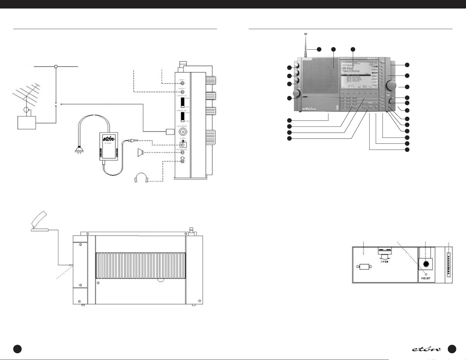
FIGURE 1: E1 INSTALLATION DIAGRAM
Low Impedance Antenna To Tape Recorder
TV/FM
Splitter
XM Radio Home Digital Antenna (Optional)
or Stereo System
AC
Adapter
External
Speaker
Stereo Headphones
From CD or
Tape Player
PAL
Connector
LEFT VIEW
E1 FRONT PANEL DESCRIPTION
2223
1
2
3
4
5
6
7
8
1. Squelch
This control allows muting of the receiver’s audio when
no signals are present. Adjust the control until background noise just disappears when no signal is being
received. An indicator is provided on the display directly
under the signal strength display to show how the
squelch is set relative to received signal strength. (See
the display description starting on page 18). Squelch
also sets the threshold for carrier scan stop. Muting can
be disabled in AUDIO SETTINGS menu, Item 4. However,
carrier stop threshold will be controlled by the Squelch
control regardless of whether or not muting has been
disabled. This control has no effect in XM mode.
2. Treble
This control adjusts the audio frequency response at the
high end of the audio spectrum. Adjust clockwise for
more treble response.
21
20
19
18
17
16
15
14
13
12
11
10
9
Contrast Knob, and to the Factory Programming
Connector. The Factory Programming Connector should
be used only by a factory authorized service center. The
Display Contrast Knob should be adjusted for best display contrast from the normal viewing position.The
Reset button “reboots” the microprocessor and should
be pressed using a straightened paperclip in the unlikely
event that the receiver exhibits erratic operation,
“freezes”, or displays a flashing “UNLOCK”on the display. (See the following diagram for the location of
these items).
Battery
Access
Panel
Reset
Button
Display
Contrast
Knob
Factory
Programming
Connector
3. Bass
This control adjusts the audio frequency response at the
low end of the audio spectrum. Adjust clockwise for
XM Digital Antenna Jack
more bass response.
(on right side)
REAR VIEW
4. Volume
With the receiver on, adjust this control clockwise to
increase the audio level from the receiver’s speaker or
from headphones. Be certain to set the volume setting
at the desired level for TIMER use.
5. Access Door
Provides access to the battery access panel, to the
microprocessor Reset button access hole, to the Display
6. Direct- Key-Input
Numeric Keys - Keys 0 thru 9 plus the ‘.’ key are used to
make direct numeric entries of frequencies,memory
channel numbers, meter band designators, menu selections, and timer settings.
CLEAR / LOCK - Press this key to clear an incorrectly
entered frequency or other value. Pressing and holding
this key for three seconds will cause the receiver to be
12 13

E1 MANUAL
E1 FRONT PANEL DESCRIPTION continued
locked in its present configuration.All front panel key
controls as well as the ‘TUNING’ knob will be ineffective, and “LOCK” and “TUN LOCK“ will appear on the
LCD display.To return to normal operating mode,once
again press the ‘CLEAR/LOCK’ key for three seconds.
This control can also be used when the receiver is
turned off. Press ‘CLEAR/LOCK’ for 3 seconds.A message will appear confirming lock. If power is then
pressed, a “Press CLEAR/LOCK for 3 seconds to unlock”
message will appear. The user must perform this action
before the ‘POWER’ key will allow power up.
7. FM / LW / MW / SW Mode - Function Softkeys
The function of each of these softkeys is shown along
the bottom edge of the display when the receiver is in
the ON state. From left to right their functions when a
menu is not displayed are as follows:
MENU - Pressing this softkey displays the first of several
menus used for setting clocks, timers and various other
receiver functions. Each additional press advances to
another menu page.
AGC - Pressing this softkey will toggle the AGC decay
time between fast, slow,and auto in all modes but FM.
When in FM mode, there will be no display function
shown for this softkey.
BW - Press repeatedly to scroll through the three available IF bandwidths of 7.0, 4.0, and 2.3 kHz in all modes
but FM. When in the FM mode, there will be no display
function shown for this softkey.
PBT - Pressing this softkey enables/disables the function
of the PBT (passband tuning) knob in all modes except
FM. The displacement in kHz of the IF passband relative
to its nominal position is shown on the display directly
above the PBT softkey when it is enabled.When in FM
mode, there will be no display function shown for this
softkey.
AM - Press to select AM (amplitude modulation) mode.
When AM mode is selected, a second press of the softkey selects AM synchronous detection mode (AM SYNC).
Repeated depressions of this softkey will cycle the synchronous detection mode on and off.When in FM mode,
there will be no display function shown for this softkey.
SSB - Press to select SSB (Single Sideband) mode. Once
SSB mode is selected, repeatedly pressing the SSB softkey will cycle between upper sideband (USB) and lower
sideband (LSB). W hen AM synchronous detection mode
is first selected using the ‘AM’ softkey, pressing the ‘SSB’
softkey will cycle between USB,DSB (double sideband)
and LSB When in FM mode, there will be no display
function shown for this softkey.
TUNE - Pressing this softkey returns to the VFO mode
from either MEMORY or COUNTRY modes.
Note that VFO (Variable Frequency Oscillator) is a register used to store the frequency to which the main ‘TUNING’ control is set. Turning the ‘TUNING’ control will
change this frequency.
Pressing ‘TUNE’ transfers the frequency last listened to
while in the MEMORY or COUNTRY modes to the VFO,
along with the current associated function parameters.
This allows for fine tuning of and around the transferred
frequency or modifying its parameters.When ‘TUNE’ is
pressed, “VFO STORED” will briefly appear on the display.This softkey is functional in MEMORY and COUNTRY modes only.
8. < SELECT >
In VFO mode, pressing the ‘<’ or ‘>’ ends of this key will
cause the frequency to increment or decrement in 5 kHz
steps on LF and SW bands, in either 9 or 10 kHz steps
on the MW (AM broadcast) band depending on a menu
setting, and in 100 kHz steps on the FM band.When in
MEMORY or COUNTRY modes, each press of the ‘<’ or
‘>’ ends of the key causes the display to decrement or
increment respectively one memory page.When in
MEMORY or COUNTRY modes, holding down the ‘<’ or
‘>’ will cause the unit to scroll through the MEMORY or
COUNTRY pages. When programming in MEMORY
mode, pressing ‘<’ or ‘>’ moves the curser left or right
respectively for entering the names for stored frequencies.
9. STORE
This key is used to store various pieces of information
including setting the Local and GMT clocks, setting
parameters and labels in the 500 MEMORY channels,
and saving parameters in the 1200 COUNTRY channels.
10. DELETE
Use this key to delete entries in the 500 MEMORY, 1200
COUNTRY, or 20 XM FAV channels.
11. TAG
Pressing this key adds (or removes) a tag shown as a
“T” on MEMORY, COUNTRY, and XM displays from any
of the MEMORY, COUNTRY, or XM channels,for selective
scanning.
12. T. SCAN
E1 FRONT PANEL DESCRIPTION continued
Used to initiate or stop a scan of MEMORY, COUNTRY
or XM channels marked with a “T”tag.
13. SEEK
Pressing the SEEK key will cause the frequency to increment in 5 kHz steps on LW, and SW modes, 9 or 10 kHz
steps in MW,depending on the setting of item 4 in the
“RADIO SETTINGS” menu, and 200 kHz steps on FM
mode, until a signal is encountered that is stronger than
the SQUELCH setting. While SEEK is engaged, the word
“SEEK” will appear on the display.
14. TIME
Pressing the ‘TIME’ key will cause the TIMER 1 screen to
appear on the display, allowing TIMER 1 to be enabled
or disabled. Pressing it a second time will cause the
TIMER 2 screen to appear, allowing it also to be enabled
or disabled. Pressing the TIME key the third time brings
up the “CLOCKS” menu which will allow selection of
GMT or LOCAL time for the time display. Pressing the
‘TIME’ key the fourth time will return the display to the
VFO, MEMORY, COUNTRY or XM screens, depending
upon which of these screens was being displayed when
the ‘TIME’ key was pressed the first time. The receiver
displays the time when in the off mode, and when in
this state, pressing the ‘TIME’ key will toggle the display
between Local and GMT time.
15. PBT
The PBT (PassBand Tuning) knob varies the IF passband
of the receiver plus or minus 2 kHz relative to the detector beat frequency oscillator (BFO) in SSB mode, and relative to the displayed frequency when on AM mode. This
is particularly useful in reducing or eliminating interference to the desired signal from nearby signals.The PBT
knob will be ineffective unless the ‘PBT’ softkey beneath
the display is pressed. The amount of IF frequency displacement from nominal will be displayed directly above
the ‘PBT’ function label on the display.PBT tuning is not
available in FM,AUX, or XM modes.In MEMORY or
COUNTRY modes, the stored PBT value will always be
recalled and “MEM” will be indicated above the ‘PBT’
softkey until changed.
16. DX
The ‘DX’ softkey turns on or off an RF preamplifier which
is useful in improving the readability of very weak signals, especially when using the built in telescopic antenna or other short antennas.When the preamplifier is
enabled, “DX”will appear on the display. When using
long antennas or when the receiver is in close proximity
to very strong broadcast transmitters, the receiver will
perform best with ‘DX’ off. The DX function is not available in AUX or XM Radio modes. Note that battery life
will be reduced somewhat if DX is enabled during
portable operation.
17. FAST / TUNING LOCK
Repeatedly pressing the FAST / TUNING LOCK key cycles
through the available tuning rates for the current operating mode, as explained in more detail under “Tuning”
which follows. Holding down the ‘FAST / TUNING LOCK’
key for approximately 2 seconds will lock out the ‘TUNING’ knob and will cause “TUN LOCK” appear on the
display. Depressing the key again for approximately 2
seconds will unlock the ‘TUNING’ knob and “TUN
LOCK” will disappear from the display.
18. Tuning
The 'TUNING' knob is the primary tuning control of the
E1 receiver. In VFO mode, clockwise rotation of the dial
increases frequency and counterclockwise rotation
decreases frequency.The rate at which frequency is
increased or decreased is determined by the band being
tuned and by pressing the ‘FAST/TUNING LOCK’ key on
a given band. In VFO mode, the ‘FAST/TUNING LOCK’
key also changes the displayed frequency resolution. In
MEMORY mode, the ‘TUNING’ knob scrolls through the
500 MEMORY channels one at a time. If the ‘FAST/TUNING LOCK’ key is pressed,“FAST” appears on the display and the ‘TUNING’ control scrolls through the 500
MEMORY channels 10 at a time as long as the ‘TUNING’ knob is being turned. If the ‘TUNING’ knob is not
moved for three seconds, the “FAST” on the display will
disappear and the ‘TUNING’ knob will revert to tuning
MEMORY channels one at a time.
The ‘TUNING’ knob is also used when programming in
MEMORY mode to scroll through all available alphanumeric characters when entering names for each MEMORY entry.
In COUNTRY mode, the ‘TUNING’ knob scrolls through
COUNTRY memory channels one at a time. If the
‘FAST/TUNING LOCK’ key is pressed,“FAST” appears on
the display and the ‘TUNING’ knob scrolls through the
available countries one country at a time with 10 memory channels being available per country.
In SW BAND mode, the ‘TUNING’ control will scroll
through the available shortwave broadcast bands from
120 meters through 11 meters.
In XM mode, the ‘TUNING’ knob scrolls through XM-ALL
channels, all channels in a given CATEGORY, or all
FAVORITE channels one at a time. If the ‘FAST/TUNING
LOCK’ key is pressed,“ ” appears on the display and
FAST the ‘TUNING’ knob scrolls through XM-ALL chan-
14
15
E1 MANUAL
E1 FRONT PANEL DESCRIPTION continued
nels six at a time. If the ‘FAST/TUNING LOCK key is
pressed when in the CATEGORY or FAVORITES modes,
the receiver will revert to XM-ALL mode.
19. Mode Softkeys
The purpose of each of these softkeys is shown along
the right edge of the display when the receiver is in the
ON state. From top to bottom their descriptions are as
follows:
XM - Pressing this softkey activates the optional XM
Satellite Radio mode and brings up the basic XM Radio
display. If this key is pressed when XM is not installed,
an error beep will be heard, and “CHECK ANTENNA”
will appear on the display.
FM / AUX - Pressing this softkey toggles between the
FM broadcast band and the AUX function. The selected
function will be in reverse video.The first press of this
softkey selects the FM broadcast band (76.0 - 90.0 MHz
or 87.0 -108.0 MHz) and causes the label for this key to
appear as “ FM / AUX ”. When in FM mode, only the
MENU function softkey along the bottom of the display
will be active. Pressing this softkey a second time tog-
Shortwave Band Designators
Low High FreqBand
120 Meter
90 Meter
75 Meter
60 Meter
49 Meter
41 Meter
31 Meter
25 Meter
22 Meter
19 Meter
16 Meter
13 Meter
11 Meter
2300 kHz
3200 kHz
3900 kHz
4750 kHz
5800 kHz
7100 kHz
9500 kHz
11,600 kHz
13,570 kHz
15,100 kHz
17,480 kHz
21,450 kHz
25,600 kHz
MW / LW - Repeatedly pressing the ‘MW / LW’ softkey
toggles between the LW band (100 - 499.99 kHz) and
the MW band (500 - 1799.99 kHz).
gles to the AUX function which causes the softkey label
to appear as “ FM / AUX ”. The AUX function allows
stereo audio fed into the LINE IN connector on the side
panel to be fed to the internal speaker or to headphones plugged into the stereo headphone jack, which
is also on the side panel. The ‘VOLUME’,‘TREBLE’, and
‘BASS’ controls will be active in this mode.
SW BAND - Pressing the ‘SW BAND’ softkey once
enables the shortwave band (1.800 - 30.000 MHz).The
display will appear as “ SW BAND ”. Pressing the ‘SW
BAND’ softkey again once SW has been selected will
cause the ‘--’ portion of “SW -- M”on the display to
flash and the display will show “ SW BAND ” for
approximately SW BAND 2 seconds During this 2 second interval, entering the meter designator for the
desired meter band will cause the receiver to go to the
low end of the frequency range for the desired meter
band. During this 2 second interval one can also scroll
through the available SW bands using the ‘TUNING’
knob or the ‘< SELECT >’ key. Each keypress or TUNING
input resets the two second timer. The frequency ranges
for the defined meter shortwave bands are as shown in
the ‘Shortwave Band Designators’ table which follows.
MEMORY - Selects MEMORY mode which allows programming or listening to the programmed contents of
memory channels 1 through 500.
2500 kHz
3400 kHz
4000 kHz
5060 kHz
6200 kHz
7600 kHz
9900 kHz
12,100 kHz
13,870 kHz
15,800 kHz
17,900 kHz
21,850 kHz
26,100 kHz
E1 FRONT PANEL DESCRIPTION continued
20. POWER
Pressing this key toggles the unit on and off.
21. Display
This is a dot matrix LCD display.See the DISPLAY
description for details.
22. Speaker
This is the opening for the internal speaker for the E1
receiver.
23. Telescopic Antenna
This is a 39 1/4“ (1.003 meters) telescopic antenna for
use on all bands except XM.
TOP PANEL DESCRIPTION
1
1. TELESCOPIC ANTENNA
This is a 39 1/4“ (1.003 meters) telescopic antenna for
use on all bands except XM.
2. LIGHT
Pressing this key while the receiver is turned ON cycles
the display illumination through four brightness states;
Off, Dim, Medium and Bright.
When the receiver is in the OFF state and connected to
external power, the display, when lit, will be DIM.
Pressing the ‘LIGHT button will cycle the display illumination on and off with no time out.
If the unit is operating from batteries, the display will be
lit only briefly when the unit is turned OFF. If, when OFF,
the ‘LIGHT’ button is pressed once,the display will illuminate for 10 seconds and then go out. In the ON state,
the display will be lit only briefly following control inputs.
However, holding down the LIGHT key for 3 seconds will
override the time out and allow the light to remain on
continuously when the receiver is ON.The user must keep
in mind, however that keeping the light on continuously
when operating on batteries will considerably reduce battery life. More details concerning display illumination can
be found on page 57 under “DISPLAY LIGHTING”.
2
3
3. SNOOZE / SLEEP
When the receiver is ON, or turned on by the timer, pressing this bar will activate the SNOOZE mode, causing the
receiver to turn OFF for 5,10, 20, or 30 minutes, depending upon the setting of item 5 of the “CLOCK MODES”
menu. After the selected number of minutes have passed,
the receiver will turn back on.To cancel a SNOOZE period
early, cycle power OFF/ON with the ‘POWER’ key.When
SNOOZE mode is active,“SNOOZE” will appear on the
display.
When the receiver is OFF, other than in SNOOZE,pushing
this bar will activate the SLEEP timer. This will turn the
receiver ON for the default set time of 15 minutes, after
which it will turn back OFF. To change the set time length
from the default 15 minutes to 1 through 99 minutes,
turn the receiver OFF and rotate the ‘TUNING’ control
after pressing the SNOOZE / SLEEP bar. After setting the
desired SLEEP time, press the bar again to activate SLEEP
mode, or automatic entry will occur in 15 seconds. The
displayed time is always in minutes.When SLEEP mode is
active, a flashing “s XX” will appear in the lower left
hand corner of the display, where “XX” is a number indicating the minutes of SLEEP time remaining.
VFO - This softkey returns to the VFO mode from MEMORY or COUNTRY modes. The frequency displayed will
be the same as the frequency last selected in VFO
mode before MEMORY or COUNTRY modes were
selected.
16
COUNTRY - Selects COUNTRY mode which allows programming or listening to the contents of memory
channels 501 through 1700. These 1200 memory
channels are divided among 111 countries from
Afghanistan to Yugoslavia with 10 memory channels
per country, and with 90 memory channels remaining
with no country assigned.
17
E1 MANUAL
E1 DISPLAY DESCRIPTION
The following section describes the main display which
will be seen when operating in the VFO mode, This is
the display which the user will see most of the time.
There are several other screens which may appear on
this display under various conditions.These additional
conditions will be covered later.
1. SIGNAL
The signal meter indicates the signal strength of the
incoming signal. The stronger the signal, the more vertical bars appear from left to right across the display.
From 100 through 30,000 kHz, the signal meter is calibrated in S units from 1 thru 9 and in decibels (dB)
above S9 up to +60 dB. On the FM band, the signal
strength is just relative.
2. SQUELCH LEVEL INDICATOR
This bar advances as the ‘SQUELCH’ knob is turned
clockwise. It indicates the level at which the incoming
signal is strong enough to overcome the SQUELCH setting. If the SQUELCH muting is enabled (which is done
by menu) a signal level that is higher than the
SQUELCH setting will be audible, while one that is
below the SQUELCH setting will not. A signal stronger
than the SQUELCH setting will cause scanning to stop
on that frequency if the “CARRIER” stop mode is
selected in the “RADIO SETTINGS” menu (item 2).
3. INTERNAL/EXTERNAL ANTENNA INDICATOR
EXT ANT or INT ANT will be displayed depending upon
whether or not the mode in use (FM or HF) has its
respective antenna switch on the side panel in the
internal or external position.
18
4. DX
This indicator appears when the DX key is pressed,
indicating that an RF preamplifier has been enabled to
improve performance on weak signals.The DX setting
will slightly reduce battery life when operating on battery power.
5. SEEK
This indicator is visible when the SEEK mode is enabled
by pressing the SEEK key.
6. VFO STORED
This indicator appears when the ‘TUNE’ softkey is
pressed. The ‘TUNE’ softkey is active in the COUNTRY
and MEMORY modes.
7. FREQUENCY DISPLAY
This is the main frequency readout of the receiver.
8. SW -- M
Indicates the meter band to which the receiver is tuned
when in SW mode. See the “Shortwave Band
Designators” table on page 22 for a listing of meter
bands. LW, MW or FM also appear here when those
bands are selected.
9. STEREO
STEREO or MONO appear here when on the FM band.
STEREO will appear if stereo is enabled from the
“AUDIO SETTINGS” menu, and a stereo signal is being
received.
E1 DISPLAY DESCRIPTION continued
10. MHz / kHz
Indicates whether the frequency displayed is shown in
megahertz or kilohertz.
11. MENU
Labels the ‘MENU’ softkey which is used to bring up a
series of menus. Repeatedly pressing this key will
advance through additional menu pages.
12. AGC
Labels the ‘AGC’ (Automatic Gain Control) softkey and
shows its release time status (Slow, Fast, or Auto).
Auto mode selects SLOW release time but automatically switches to fast release only while tuning.
13. BW
Labels the Bandwidth softkey and shows its status
(2.3, 4.0, or 7.0 kHz).
14. PBT
Labels the ‘PBT’ softkey. The ‘PBT’ softkey enables and
disables the ‘PBT’ (Passband Tuning) knob. W hen the
softkey is enabled, its frequency displacement relative
to nominal is shown above “PBT”.The reading will be
between +2.0 and - 2.0 kHz.
15. AM
Labels the ‘AM’ softkey, and shows its status.The ‘AM’
softkey enables AM mode. When AM is enabled,“AM”
appears over the “AM” softkey label. If the softkey is
pressed a second time, “AM SYNC” appears over the
“AM” label to indicate that the synchronous detector
is operating.
16. SSB
This labels the ‘SSB’ softkey and shows its status.
Pressing the ‘SSB’ softkey enables single sideband
reception, causing either “USB” or “LSB” to appear
above the “SSB” label. Pressing the ‘SSB’ softkey again
after SSB is selected will toggle the display between
“USB” and “LSB”.When AM SYNC has been selected,
pressing the ’SSB’ softkey will toggle through the
modes of the AM synchronous detector: USB, LSB and
DSB.
17. COUNTRY
This labels the ‘COUNTRY’ softkey. When this softkey is
pressed, Country mode is selected and the label
appears as “COUNTRY”.
18. TUN LOCK
This indicator appears when the ‘FAST / TUNING LOCK’
softkey has been pressed for 2 seconds. It indicates
that the ‘TUNING’ knob has been locked out and will
have no affect.
19. MEMORY
This labels the ‘MEMORY’ softkey. W hen this softkey is
pressed, MEMORY mode is selected and the label
appears as “MEMORY”.
20. VFO
This labels the ‘VFO’ softkey.W hen this softkey is
pressed, the receiver returns to the VFO mode from
COUNTRY or MEMORY modes, but the frequency being
received from the MEMORY or COUNTRY modes is not
transferred. The frequency displayed will be the same
as was last being received when last in VFO mode. The
indicator will appear as “VFO” when VFO mode is
active.
21. MW / LW
This indicator labels the ‘MW / LW’ select softkey.
Pressing this softkey will select either MW (AM
Broadcast) or LW (Long Wave) frequency ranges.
Repeatedly pressing this softkey will toggle between
these two modes. Depending upon the mode selected,
this indicator will appear either as “MW / LW” or
“MW / LW”.
22. SW BAND
This indicator labels the ‘SW BAND’ softkey. Pressing
this softkey once selects the SW (Short Wave) band
(1.8 - 30.0 MHz). This gives an indication of “SW
BAND” on the display. Pressing this softkey a second
time causes the display to appear as “SW BAND”, and
permits the tuning knob or the ‘< SELECT >’ key to
scroll through the available meter bands as shown on
the “Shortwave Band Designator” table on page 16. If
no movement of the ‘TUNING’ knob or input to the ‘<
SELECT >’ key occurs for 3 seconds, the display will
revert back to “SW BAND” and normal tuning will
resume.
23. FM / AUX
This labels the ‘FM / AUX’ select softkey. Pressing this
softkey once selects the FM Broadcast band (76 - 90
MHz or 87 - 108 MHz) and causes the indicator to
appear as “FM / AUX“. The second press of this softkey activates the AUX mode and causes the indicator
to appear as “FM / AUX“. Selecting this mode enables
audio fed in the LINE IN jack on the side panel to be
fed through to the E1 receiver’s audio system.
24. XM
This indicator labels the ‘XM’ softkey. Pressing this key
activates the optional XM Satellite Radio mode.When
XM is activated, the basic XM radio display will appear.
If XM is not installed, an error beep will be heard, and
“CHECK ANTENNA” will appear on the display.
19
E1 MANUAL
E1 DISPLAY DESCRIPTION continued
25. TIMER 1 2
This display appears when one or both of the event
timers are enabled.
26. Time Display
This displays the time, which can be either Greenwich
Mean Time (GMT) or Local time (L). If the time display
is flashing, this is an indication that the time has not
been set. See “Clock and Timer Functions” on page
52.
27a. LOW BATT
This flashing reverse video indicator appears when no
external AC Adaptor is connected, and the battery voltage is too low for satisfactory operation. If this flashing
indicator is seen, the batteries should be replaced.
27b. POWER LOSS
This indicator, which appears in the same location on
the display as “LOW BATT”, will be seen when the
unit is connected to external power, and that external
SIDE PANEL DESCRIPTION
1
2
3
4
5
6
7
8
9
20
power is lost. It means that the receiver is operating
from the internal batteries, if so equipped. If the
POWER LOSS BEEP is enabled (AUDIO SETTINGS
menu, selection 3), there will also be four beeps in
rapid succession, once per minute. (Volume controlled).
28. LOCK
This indicator appears when the ‘CLEAR/LOCK’ key has
been pressed for 3 seconds.W hen this condition
exists, all front panel keys (except for ‘CLEAR/LOCK’)
plus the ‘TUNING’ and ‘PBT’ knobs will be ineffective.
Pressing ‘CLEAR/LOCK’ again for 3 seconds will enable
normal operation, and the “LOCK” indicator will disappear.
29. ERROR
This indicator will appear along with an audio beep
when an error condition exists, such as pressing one of
the softkeys which has no label in the mode selected.
1. TELESCOPIC ANTENNA
The receiver has a built-in telescopic antenna that can
be used on all bands.
Note that the pivot point section
of the antenna must be exposed out of its nesting tube
to permit moving the antenna from its vertical orientation.
Extend the telescopic sections and position the
antenna for best signal reception. Be sure the corresponding side panel antenna select switches are set to
the ‘INTERNAL’ position for TELESCOPIC antenna
reception.
2. LINE IN
This 1/8" diameter stereo jack is used to feed in audio
from an external source such as a CD or cassette tape
player. The input level should be approximately 300
mV, at an impedance of 47K ohm.This input is enabled
when the AUX mode is selected. When in this mode,
the VOLUME, BASS and TREBLE controls are effective.
3. LINE OUT
This 1/8" diameter stereo jack provides a constant low
level audio source that is independent of the front
panel ‘VOLUME’,‘TREBLE’ and ‘BASS’ control settings.
It is designed to interface to a tape recorder, CW /
RTTY demodulators,stereo amplifiers, etc.
SIDE PANEL DESCRIPTION continued
4. ANTENNA HF
This switch selects between the internal TELESCOPIC
antenna and the external antenna connector when
receiving LW, MW, or SW frequency ranges.
5. ANTENNA FM
This switch selects between the internal TELESCOPIC
antenna and the external antenna connector when
receiving the FM Broadcast band (76 - 90 MHz or 87 –
108 MHz).
6. EXT ANTENNA
This PAL type male input connector is designed for an
unbalanced 50 to 75 ohm input connection that is
encountered with coaxial feeds.
GETTING STARTED
GENERAL OPERATING INFORMATION
The etón E1 receiver has been designed for ease of
use. Please take a few moments to read through this
section and familiarize yourself with general operating
information.
In this manual, the term AM stands for Amplitude
Modulation, not the commercial AM broadcast band of
530 - 1710 kilohertz.
When referring to the commercial AM broadcast band,
the term MW (medium wave) is used.
FIRST STEPS
Please refer to the front panel illustration on page 13
and set the controls as described below.
(1) Install 4 "D" batteries or connect AC ADAPTER.
(2) Fully extend the telescopic antenna and adjust to a
vertical position, or connect an external antenna to
the side panel EXT. ANTENNA jack. Set side panel
‘ANTENNA HF’ and/or ‘ANTENNA FM' switch(es) to
appropriate position(s) (INTERNAL or EXTERNAL).
Plug the XM Satellite antenna into the jack on the
right side panel, if you have purchased the XM
Satellite Radio option.
(3) Press ‘POWER’ and adjust ‘VOLUME’ to a comfort-
able level.
(4) Select the desired band by pressing the ‘FM’,‘SW’,
‘MW/LW’, or ‘XM’ (if applicable) softkeys until the
desired band is displayed on the front panel display.The selected band will be indicated by reverse
video on the display. For example: “MW / LW “.
(5) Enter the desired frequency by using one of several
methods as described in “DIRECT FREQUENCY
ENTRY” or use the ‘TUNING’ knob to tune until the
desired frequency is displayed.
7. DC IN 9 V
Connect the AC ADAPTER wall transformer output
cable to this connector. The receiver requires 9 VDC
power at approximately 1 Amp current.With external
DC power applied, the internal batteries are not used.
8. EXT SPEAKER
This 1/8“ monophonic connector provides 1.25 to 3.0
watts audio output for an external 4 to 8 ohm speaker.
9. HEADPHONE
This connector accepts a 1/8" (3.175 mm)
stereo/mono headphone connector. Stereo reception is
possible only in the FM and XM Radio modes.All
speaker outputs are automatically switched off when
using the headphones..
DIRECT FREQUENCY ENTRY
Direct entry of a desired frequency is possible using the
‘Direct-Key-Input’ keys. While entering a frequency, if
an incorrect frequency is entered, pressing the
‘CLEAR/LOCK’ key will clear the entry in progress and
return the receiver to its previous settings.The second
depression of the decimal (.) key acts as an ‘ENTER'
and causes immediate response to the entered frequency. If you do not press the decimal (.) key a second time at the end, the receiver will automatically
enter the frequency after a slight delay.
Enter frequency as follows:
(A) The LW and MW (AM broadcast) bands enter and
display in kHz (Kilohertz). A maximum of 6 digits may
be entered.
Examples:
700 KHz
Press ‘7', ’0' , ’0' , ’.’ ,’ .’ **
1290.00 kHz
Press ‘1', ‘2', ‘9',‘0', ‘.’,‘0’, ‘0’ *
* When the maximum number of allowed digits is
entered, the decimal point will be automatically placed
between the 1 kHz and .1 kHz digits and need not be
entered.
** The second depression of the ‘.’ key acts as an
‘ENTER’ and causes immediate response to the
entered frequency. If you do not press the decimal ‘.’ a
second time at the end, the receiver will automatically
enter the frequency after a slight delay.
21
E1 MANUAL
GETTING STARTED continued
(B) The SW band (1.8 - 30.0 MHz) frequencies are displayed and entered in kHz or MHz, depending upon
the user’s selection from item 5 of the RADIO SETTINGS menu. A maximum of 7 digits may be entered.
To make the menu selection, press the ‘MENU’ softkey
once.Then press ‘Direct-Key-Input’ key ‘5'. Repeatedly
pressing the ‘5' key toggles between kHz and MHz as
the display and entry method for the SW band. Leave
the reverse video entry 0on the desired display
method. For example, line 5 on the menu should
appear as follows for entry in kHz:
“ 5 SW BAND ENTRY kHz / MHz“.
After making this selection, press ‘Direct-Key-Input’ key
‘9' to exit the menu. Note that if kHz is selected from
the menu, the display will show frequencies from 1.8 -
30.0 MHz in Kilohertz, and entries should be made in
kHz.
Example:
14,258.1 kHz
Press ‘1', ‘4', ‘2',‘5', ‘8', ’.’,‘1', ‘.’ **
OR Press ‘1', ‘4', ‘2', ‘5', ‘8', ‘.’, ‘1',‘0' *
If MHz was selected from the menu all frequency
entries should be made in MHz.
Example:
14.2581 MHz
Press ‘1', ‘4', ‘.’, ‘2', ‘5',‘8', ‘1', ‘.’ **
OR Press ‘1', ‘4', ‘.’,‘2', ‘5',‘8', ‘1',‘0' *
* When the maximum number of allowed digits is
entered, the 7th digit acts as an enter key, and a second ‘.’ need not be entered.
** The second depression of the ‘.’ key acts as an
‘ENTER’ and causes immediate response to the
Shortwave Band Designators
Low High FreqBand
120 Meter
90 Meter
75 Meter
60 Meter
49 Meter
41 Meter
31 Meter
25 Meter
22 Meter
19 Meter
16 Meter
13 Meter
11 Meter
2300 kHz
3200 kHz
3900 kHz
4750 kHz
5800 kHz
7100 kHz
9500 kHz
11,600 kHz
13,570 kHz
15,100 kHz
17,480 kHz
21,450 kHz
25,600 kHz
entered frequency. If you do not press the decimal ‘.’ a
second time at the end, the receiver will automatically
enter the frequency after a slight delay.
(C) FM broadcast band enters and displays in MHz
(megahertz) regardless of the RADIO SETTINGS menu
setting. A maximum of 5 digits may be entered for FM.
Examples:
97.7 MHz
Press ‘9', ‘7', ‘.’, ‘7' ‘.’ **
107.7 MHz
Press ‘1', ‘0', ‘7',‘.’, ’7', ‘.’ **
OR Press ‘1', ‘0', ‘7', ‘.’, ‘7',‘0' *
Attempting to enter a frequency outside the tuning
range of the
etón E1 receiver will cause the ERROR
annunciator to flash and an error beep to be heard.
The receiver will then return to its previous settings.
SHORTWAVE ‘METER' BAND DESIGNATOR ENTRY
To facilitate tuning to particular sections of the shortwave band that contain many worldwide broadcasts of
news, information and music, the etón E1 receiver permits entry of the ‘METER' band designator. In some
cases, the worldwide broadcast station may not
announce its exact operating frequency, but will
announce the ’METER' band in which it is operating or
to which band it will move to improve worldwide
reception at a particular time of day. By entering this
'METER' band number, the receiver automatically tunes
to the low frequency end of the corresponding
‘METER' band. The search for the new station location
is thus limited to a particular smaller section of the
entire shortwave band spectrum.
The Shortwave Band Designators and corresponding
frequency ranges are as follows:
2500 kHz
3400 kHz
4000 kHz
5060 kHz
6200 kHz
7600 kHz
9900 kHz
12,100 kHz
13,870 kHz
15,800 kHz
17,900 kHz
21,850 kHz
26,100 kHz
GETTING STARTED continued
Press the ‘SW BAND’ softkey to enter the shortwave
band tuning mode.The SW portion of the display indicator will now be in reverse video. Now press the ‘SW
BAND’ softkey a second time.
The display indicator will now appear as “SW BAND”,
and the ‘METER’ number entry prompt on the display
will be flashing. (See #8 on the LCD Display
Description on page 18). At this point, you have
approximately 3 seconds to do one of the following:
(1) You can enter a shortwave band ‘METER’ number
with the ‘Direct-Key-Input’ keys. For example, key in
‘4', ‘1' for the 41 meter band.
(2) You can scroll through the available meter bands
using the ‘TUNING’ knob or the ‘< SELECT >’ key,
stopping on the desired ‘METER’ band. If you stop
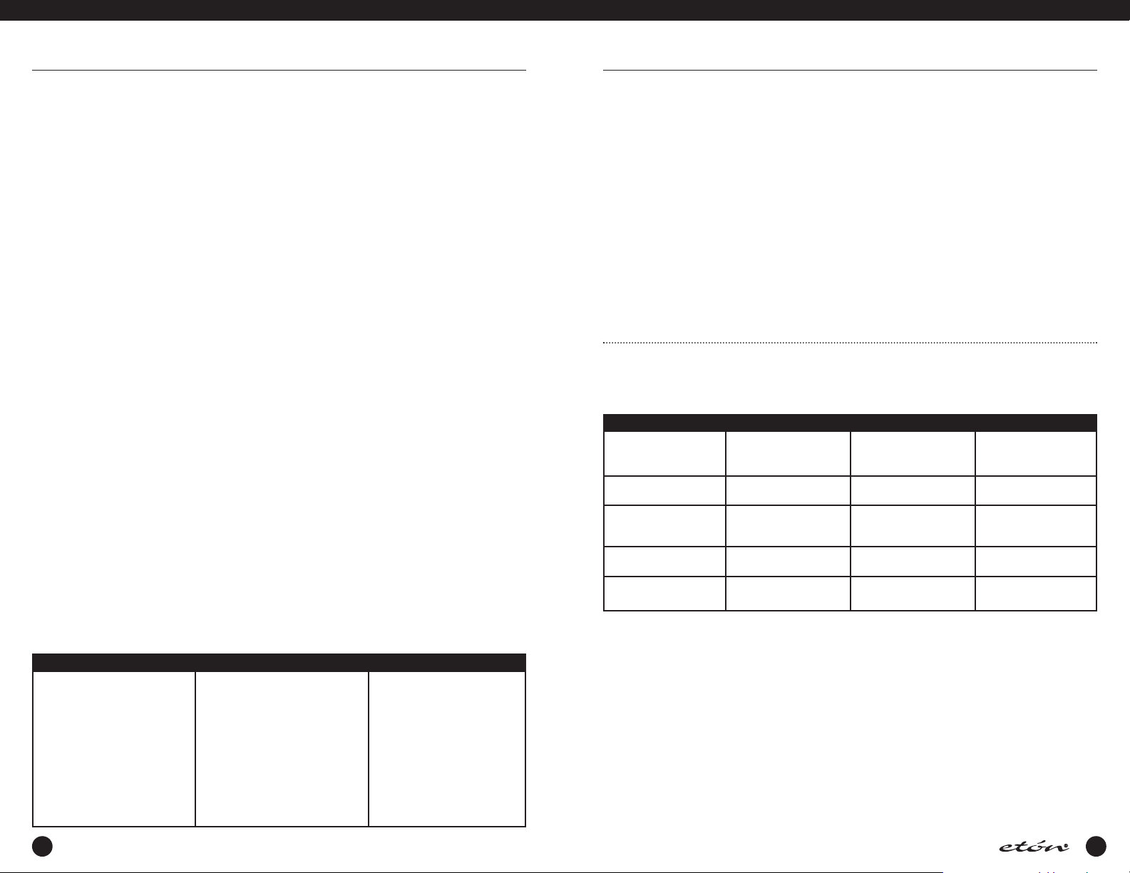
FREQUENCY RESOLUTION
The E1 receive tunes in the following steps:
Display *ResolutionMode
MW AM: 10 Hz
MW SSB: 10 Hz
LW & SW AM 10 Hz
LW & SW SSB 10 Hz
FM 10 kHz
* Selectable using ‘FAST’ button.
FRONT PANEL LOCK (UNLOCK)
All front panel keys (with the exception of the ‘CLEAR /
LOCK’ key), as well as the ‘TUNING’ knob can be
locked if desired. First, be sure the E1 receiver is not in
T.SCAN or SEEK mode. Press and hold the
‘CLEAR/LOCK’ key which is one of the ‘Direct-KeyInput’ keys.The “LOCK” and “TUN LOCK” annunciators will appear indicating the front panel controls are
locked out. ‘‘VOLUME’,‘BASS’, ‘TREBLE’, and
‘SQUELCH’ are still functional. Press and hold the
‘CLR/LOCK’ key to unlock.The “LOCK” and “TUN
LOCK” annunciators will disappear, indicating the front
panel controls are once again active.The ‘CLEAR /
100 Hz
1 kHz
1 kHz
100 Hz
1 kHz
1 kHz
100 kHz
on a “METER” band for more than 3 seconds, the
receiver will tune to that band, the “SW BAND”
indicator will appear as “BAND“, and the shortwave band SW “METER” prompt will quit flashing.
To enter a shortwave band ‘METER' designator, press
the ‘SW BAND’ softkey to display a flashing ‘METER'
number entry prompt. The prompt will flash for approximately 3 seconds after the ‘SW BAND’ softkey is
pressed. While it is still flashing, enter one of the listed
two or three digit Band numbers corresponding to the
desired ‘METER' band designator using the ‘Direct-KeyInput’ keys.While the ‘METER' annunciator is flashing,
the ‘< SELECT >’ keys can also be used to step quickly
from band to band. After selection of the ‘METER’
band, use the ‘TUNING’ knob or ‘< SELECT >’ keys to
change the frequency, or press the ‘Direct-Key-Input’
keys to make a direct frequency entry.
Tuning *Resolution
10 Hz
100 Hz
1 kHz
10 Hz
1 kHz
10 Hz
100 Hz
1 kHz
10 Hz
1 kHz
20 kHz
100 kHz
< SELECT >
10 kHz /
9 kHz
10 kHz /
9 kHz
5 kHz
5 kHz
100 kHz
LOCK’ key may be used even when the radio is off to
lock the ‘POWER’ key to prevent accidental power activation.
AM SYNCHRONOUS OPERATION
For general tuning and listening, normal AM is best. If,
however, the received signal sounds distorted, or interference from adjacent stations is present, AM synchronous should be engaged. The synchronous detector in
your receiver can greatly reduce the severe audio distortion that can occur due to signal fading. The detector also permits selectable tuning to either the upper
or lower sideband portion of an AM signal. Since most
22
23
 Loading...