


Whirlpool WGD5700VW, WGD5700VH, WGD5600VQ, WGD5590VQ, WGD5510VQ Installation Instructions
...Dryer Installation Instructions
29" and 27" Wide Models
Gas (U.S.A. and Canada) & Electric (Canada Only)
Instructions D’installation de la sÉcheuse
Modèles de 29" et de 27" de largeur
À gaz (É.-U. et Canada) et Électrique (Canada uniquement)
Para obtener acceso al manual de uso y cuidado en español, o para obtener información adicional acerca de su producto, visite: www.whirlpool.com
Tenga listo su número de modelo completo. Puede encontrar el número de modelo y de serie dentro de la cavidad superior de la puerta.
Table of Contents |
|
Table des matières |
|
DRYER SAFETY.......................................................................... |
1 |
SÉCURITÉ DE LA SÉCHEUSE................................................. |
14 |
Installation Requirements............................................. |
4 |
EXIGENCES D'INSTALLATION................................................ |
17 |
Tools and Parts....................................................................... |
4 |
Outillage et Pièces............................................................... |
17 |
Location Requirements.......................................................... |
4 |
Exigences d'emplacement.................................................. |
17 |
ELECTRIC DRYER POWER HOOKUP - CANADA ONLY......... |
6 |
RACCORDEMENT À L'ALIMENTATION ÉLECTRIQUE |
|
Electrical Requirements......................................................... |
6 |
DE LA SÉCHEUSE - CANADA SEULEMENT.......................... |
19 |
Install Leveling Legs......................................................... |
6 |
Spécifications Électriques................................................... |
19 |
Gas DRYER POWER HOOKUP................................................. |
7 |
INSTALLATION DES PIEDS DE NIVELLEMENT..................... |
20 |
Gas Supply Requirements..................................................... |
7 |
RACCORDEMENT D'UNE SÉCHEUSE À GAZ....................... |
20 |
Venting..................................................................................... |
8 |
Spécifications de l'alimentation en gaz............................. |
20 |
Venting Requirements............................................................ |
8 |
ÉVACUATION............................................................................ |
22 |
Plan Vent System.................................................................... |
9 |
Exigences concernant l'évacuation.................................... |
22 |
Install Vent System............................................................... |
11 |
Planification du système d'évacuation............................... |
23 |
Level Dryer............................................................................ |
11 |
Installation du circuit d'évacuation..................................... |
24 |
Make Gas Connection.......................................................... |
11 |
Réglage de l'aplomb de la sécheuse.................................. |
25 |
Connect Vent......................................................................... |
11 |
RACCORDEMENT AU GAZ.................................................. |
25 |
Complete Installation........................................................... |
11 |
RACCORDEMENT DU CONDUIT D'ÉVACUATION............ |
25 |
Reverse Door Swing (Optional)........................................... |
12 |
ACHEVER L'INSTALLATION................................................ |
25 |
|
|
Inversion du sens d'ouverture |
|
|
|
de la porte (facultatif)........................................................... |
26 |
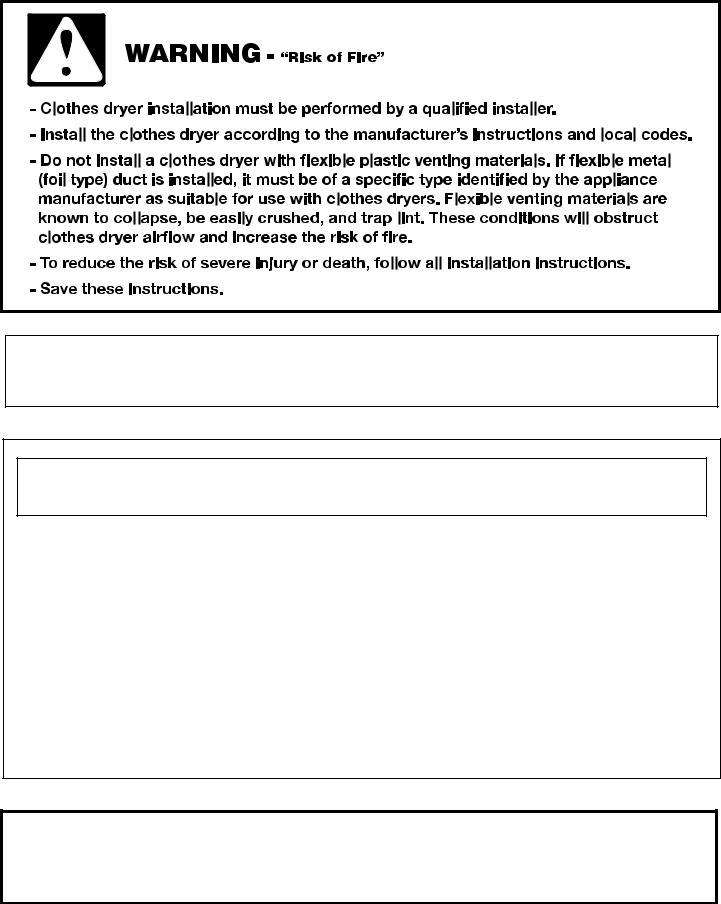
DRYER SAFETY
Your safety and the safety of others are very important.
We have provided many important safety messages in this manual and on your appliance. Always read and obey all safety messages.
This is the safety alert symbol.
This symbol alerts you to potential hazards that can kill or hurt you and others.
All safety messages will follow the safety alert symbol and either the word “DANGER” or “WARNING.” These words mean:
DANGER |
You can be killed or seriously injured if you don't immediately |
|
follow instructions. |
||
|
You can be killed or seriously injured if you don't follow |
|
WARNING |
||
instructions. |
All safety messages will tell you what the potential hazard is, tell you how to reduce the chance of injury, and tell you what can happen if the instructions are not followed.
W10296135A |
1 |
|
W10296136A-SP |
||
|
IMPORTANT: The gas installation must conform with local codes, or in the absence of local codes, with the National Fuel Gas Code, ANSI Z223.1/NFPA 54 or the Canadian Natural Gas and Propane Installation Code, CSA B149.1.
The dryer must be electrically grounded in accordance with local codes, or in the absence of local codes, with the National Electrical Code, ANSI/NFPA 70 or Canadian Electrical Code, CSA C22.1.
WARnIng: For your safety, the information in this manual must be followed to minimize the risk of fire or explosion, or to prevent property damage, personal injury, or death.
–Do not store or use gasoline or other flammable vapors and liquids in the vicinity of this or any other appliance.
–WHAT To Do IF You SmEll gAS:
•Do not try to light any appliance.
•Do not touch any electrical switch; do not use any phone in your building.
•Clear the room, building, or area of all occupants.
•Immediately call your gas supplier from a neighbor's phone. Follow the gas supplier's instructions.
•If you cannot reach your gas supplier, call the fire department.
–Installation and service must be performed by a qualified installer, service agency, or the gas supplier.
WARNING: Gas leaks cannot always be detected by smell.
Gas suppliers recommend that you use a gas detector approved by UL or CSA.
For more information, contact your gas supplier.
If a gas leak is detected, follow the “What to do if you smell gas” instructions.
2

In the State of Massachusetts, the following installation instructions apply:
Installations and repairs must be performed by a qualified or licensed contractor, plumber, or gasfitter qualified or licensed by the State of Massachusetts.
If using a ball valve, it shall be a T-handle type.
A flexible gas connector, when used, must not exceed 3 feet.
IMPORTANT SAFETY INSTRUCTIONS
When discarding or storing your old clothes dryer, remove the door.
SAVE THESE INSTRUCTIONS
3
INSTALLATION REQUIREMENTS
Tools and Parts
Gather the required tools and parts before starting installation. Read and follow the instructions provided with any tools listed here.
■■ |
Flat-blade screwdriver |
■■ 1/4" nut driver or socket |
|
■■ |
#2 Phillips head |
|
wrench (recommended) |
|
|
||
|
screwdriver |
■■ Tin snips (new vent |
|
■■ Adjustable wrench that |
|
installations) |
|
|
|
||
|
opens to 1" (25 mm) or |
■■ |
Caulking gun and |
|
hex-head socket wrench |
|
compound (for installing |
|
(for adjusting dryer feet) |
|
new exhaust vent) |
■■ |
Level |
■■ |
Tape measure |
■■ |
Vent Clamps |
■■ |
Utility knife |
■■ |
Pliers |
|
|
Gas Installations |
|
|
|
■■ 8" or 10" pipe wrench |
■■ |
Pipe joint compound |
|
■■ 8" or 10" adjustable |
|
resistant to LP gas |
|
|
|
||
wrench
Parts supplied:
Parts package is located in dryer drum. Check that all parts are included.
4 Leveling legs
Parts needed:
Check local codes. Check existing electrical supply and venting, and read “Electrical Requirements” and “Venting Requirements” before purchasing parts.
Mobile home installations require metal exhaust system hardware. For further information, please reference the “Assistance or Service” section of the “Dryer User Instructions.”
Location Requirements
You will need:
■■ A location allowing for proper exhaust installation. See “Venting Requirements.”
■■ A separate 30 amp circuit for electric dryers. ■■ A separate 15 or 20 amp circuit for gas dryers.
■■ If you are using power supply cord, a grounded electrical outlet located within 2 ft. (610 mm) of either side of dryer. See “Electrical Requirements.”
■■ A sturdy floor to support dryer and a total weight (dryer and load) of 200 lbs. (90.7 kg). The combined weight of a companion appliance should also be considered.
■■ Level floor with maximum slope of 1" (25 mm) under entire dryer. If slope is greater than 1" (25 mm), install Extended Dryer Feet Kit, Part Number 279810. If not level, clothes may not tumble properly and automatic sensor cycles may not operate correctly.
Do not operate your dryer at temperatures below 45°F (7°C). At lower temperatures, the dryer might not shut off at the end of an automatic cycle. Drying times can be extended.
The dryer must not be installed or stored in an area where it will be exposed to water and/or weather.
Check code requirements. Some codes limit, or do not permit, installation of the dryer in garages, closets, mobile homes, or sleeping quarters. Contact your local building inspector.
NOTE: No other fuel-burning appliance can be installed in the same closet as a dryer.
4
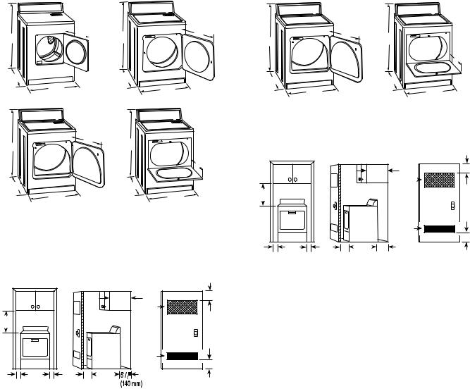
Installation clearances:
The location must be large enough to allow the dryer door to open fully.
Most installations require a minimum 5½" (140 mm) clearance behind the dryer for the exhaust vent with elbow. See “Venting Requirements.”
29" Wide Models |
27" Wide Models |
Dryer Dimensions |
Dryer Dimensions |
|
|
|
15¼" |
|
|
22¾" |
|
|
|
|
23¾" |
|
|
|
|
433/8" |
|
|
(387 mm) |
|
|
(578 mm) |
|
|
|
|
|
|
|
|
|
|
|
433/8" |
|
43" |
|
|
(603 mm) |
43" |
|
|
|
||||
(1102 mm) |
|
|
(1102 mm) |
|
|
|
|
|
|
|
|
|
|||
|
|
|
|
(1092 mm) |
|
|
|
(1092 mm) |
|
|
|
||||
|
|
|
|
|
|
|
|
|
|
|
|
|
|
|
13¾" |
|
|
|
|
|
|
|
|
|
|
|
|
|
|
|
(349 mm) |
*26" |
|
|
|
*27¾" |
|
|
*291/2" |
|
|
|
*291/2" |
|
|
|
|
(660 mm) |
|
|
|
(705 mm) |
|
|
(749 mm) |
|
|
|
|
(749 mm) |
|
|
|
|
|
|
|
|
|
|
|
|
|
|
|
|
|||
|
|
29" |
|
|
29" |
|
|
27" |
|
|
|
|
|
27" |
|
|
(737 mm) |
|
|
(737 mm) |
|
|
|
|
|
|
|
||||
|
|
A |
|
|
B |
|
|
(687 mm) |
|
|
|
|
|
(687 mm) |
|
|
|
|
|
|
|
|
A |
|
|
|
|
|
B |
||
|
|
|
|
|
|
|
|
|
|
|
|
|
|
||
|
|
|
|
|
|
|
|
|
A. Large opening side-swing door |
||||||
|
|
|
22¾" |
|
|
|
|
B. Wide opening hamper door |
|
||||||
|
|
|
|
|
|
|
|
|
|
|
|
|
|
||
433/8" |
|
|
(578 mm) 433/8" |
|
|
Installation Spacing |
|
|
|
|
|
|
|||
(1102 mm) |
|
|
|
(1102 mm) |
|
|
|
|
|
|
|
|
|||
|
|
|
|
|
|
13¾" |
|
|
|
|
|
|
|
|
3"* |
|
|
|
|
|
|
(349 mm) |
|
|
|
|
|
14"max.* |
|
|
(76 mm) |
|
|
|
|
|
|
|
|
|
|
|
|
48 in.2* |
|
||
*27¾" |
|
|
|
*27¾" |
|
|
|
|
|
|
|
(356 mm) |
2 |
|
|
|
|
|
|
|
18"* |
|
|
|
|
(310 cm ) |
|
||||
(705 mm) |
|
|
|
(705 mm) |
|
|
|
|
|
|
|
|
|||
|
|
29" |
|
|
|
29" |
(457 mm) |
|
|
|
|
|
|
|
|
|
(737 mm) |
|
|
(737 mm) |
|
|
|
|
|
|
|
|
|
||
|
|
C |
|
|
|
D |
|
|
|
|
|
|
|
|
|
|
|
A. Small opening side-swing door |
|
|
|
|
|
|
|
24 in2.* |
2 |
3"* |
|||
|
|
|
|
|
|
|
|
|
|
(76 mm) |
|||||
|
|
B. Large opening side-swing door |
|
|
|
|
|
|
|
(155 cm ) |
|||||
|
|
|
|
27" |
|
|
|
|
|
|
|
||||
|
|
C. Wide opening side-swing door |
|
1" |
1" |
1"* |
29¼" |
5½"* |
|
|
|
||||
|
|
D. Wide opening hamper door |
|
(25 mm) |
(686 mm) |
(25 mm) (25mm) (743mm) (140mm) |
|
|
|||||||
Installation Spacing |
|
|
|
|
|
A |
|
|
B |
|
|
C |
|||
|
|
|
|
|
|
A. Recessed area |
|
|
|
||||||
|
|
|
|
|
|
3"* |
|
|
|
|
|
||||
|
|
|
|
|
|
|
|
B. Side view - closet or confined area |
|||||||
|
|
|
|
14"max.* |
48 in.2* |
(76 mm) |
|
|
C. Closet door with vents |
|
|
||||
|
|
|
|
(356 mm) |
|
*Required spacing |
|
|
|
|
|
|
|
||
|
|
|
|
2 |
|
|
|
|
|
|
|
|
|||
18"* |
|
|
|
|
(310 cm ) |
|
|
|
|
|
|
|
|
||
|
|
|
|
|
|
|
|
|
|
|
|
|
|
||
(457 mm) |
|
|
|
|
|
|
Installation spacing for recessed area or closet |
||||||||
|
|
|
|
|
|
|
|||||||||
|
|
|
|
|
|
|
installation |
|
|
|
|
|
|
|
|
|
|
|
|
|
24 in.2 * |
3"* |
The dimensions shown are for the minimum spacing allowed. |
||||||||
|
|
|
|
|
■■ Additional spacing should be considered for ease of |
||||||||||
|
|
|
|
|
(155 cm )2 |
(76 mm) |
|||||||||
1" |
29" |
1" |
1"* |
27¾" |
|
|
installation and servicing. |
|
|
|
|
||||
(25 mm) |
(737 mm) |
(25 mm) (25mm) (705 mm) |
|
|
■■ Additional clearances might be required for wall, door, and |
||||||||||
|
A |
|
|
B |
|
C |
floor moldings. |
|
|
|
|
|
|
||
A.Recessed area
B.Side view - closet or confined area
C.Closet door with vents
*Required spacing
Mobile home - Additional installation requirements
This dryer is suitable for mobile home installations. The installation must conform to the Manufactured Home Construction and Safety Standard, Title 24 CFR, Part 3280 (formerly the Federal Standard for Mobile Home Construction and Safety, Title 24, HUD Part 280) or the Canadian Manufactured Home Standard CAN/CSA-Z240 MH.
■■ Additional spacing of 1" (25 mm) on all sides of the dryer is recommended to reduce noise transfer.
■■ For closet installation, with a door, minimum ventilation openings in the top and bottom of the door are required. Louvered doors with equivalent ventilation openings are acceptable.
■■ Companion appliance spacing should also be considered.
Mobile home installations require:
■■ Metal exhaust system hardware, available for purchase. For further information, please reference the “Assistance or Service” section of the “Dryer User Instructions.”
■■ Special provisions must be made in mobile homes to introduce outside air into the dryer. The opening (such as a nearby window) should be at least twice as large as the dryer exhaust opening.
5
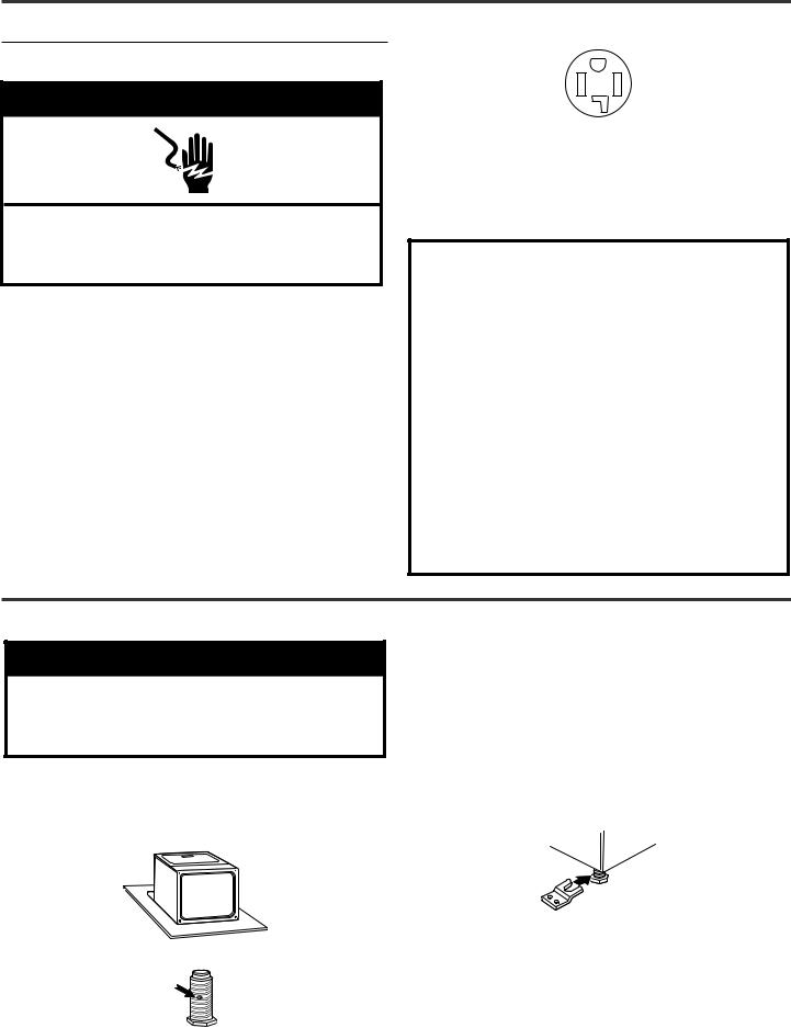
Electric Dryer Power Hookup - Canada Only
Electrical Requirements
 WARNING
Electrical Shock Hazard Plug into a grounded 4 prong outlet.
Failure to do so can result in death or electrical shock.
It is your responsibility:
■■ To contact a qualified electrical installer.
■■ To be sure that the electrical connection is adequate and in conformance with the Canadian Electrical Code, C22.1-latest edition and all local codes. A copy of the above codes standard may be obtained from: Canadian Standards Association, 178 Rexdale Blvd., Toronto, ON M9W 1R3 CANADA.
■■ To supply the required 4 wire, single phase, 120/240 volt, 60 Hz., AC only electrical supply on a separate 30-amp circuit, fused on both sides of the line. A time-delay fuse or circuit breaker is recommended. Connect to an individual branch circuit.
■■ This dryer is equipped with a CSA International Certified Power Cord intended to be plugged into a standard 14-30R wall receptacle. The cord is 5 ft. (1.52 m) in length. Be sure wall receptacle is within reach of dryer’s final location.
4-wire receptacle (14-30R)
■■ Do not use an extension cord.
If using a replacement power supply cord, it is recommended that you use Power Supply Cord Replacement Part Number 3394208. For further information, please reference the “Assistance or Service” section of the “Dryer User Instructions.”
GROUNDING INSTRUCTIONS
For a grounded, cord-connected dryer:
This dryer must be grounded. In the event of malfunction or breakdown, grounding will reduce the risk of electric shock by providing a path of least resistance for electric current.
This dryer is equipped with a cord having an equipmentgrounding conductor and a grounding plug. The plug must be plugged into an appropriate outlet that is properly installed and grounded in accordance with all local codes and ordinances.
WARNING: Improper connection of the equipmentgrounding conductor can result in a risk of electric shock. Check with a qualified electrician or service representative or personnel if you are in doubt as to whether the dryer is properly grounded. Do not modify the plug provided with the dryer: if it will not fit the outlet, have a proper outlet installed by a qualified electrician.
SAVE THESE INSTRUCTIONS
Install Leveling Legs
 WARNING
Excessive Weight Hazard
Use two or more people to move and install dryer. Failure to do so can result in back or other injury.
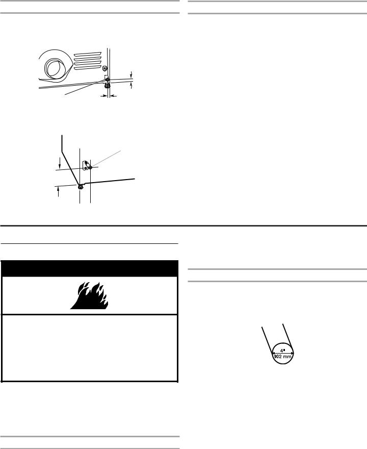
1.To avoid damaging the floor, use a large flat piece of cardboard from the dryer carton. Place cardboard under the entire back edge of the dryer. See illustration.
2.Firmly grasp the body of the dryer (not the console panel). Gently lay the dryer on the cardboard. See illustration.
4.Screw the legs into the leg holes by hand. Use a wrench to finish turning the legs until the diamond marking is no longer visible.
5.Place a carton corner post under each of the 2 dryer back corners. Stand the dryer up. Slide the dryer on the corner posts until it is close to its final location. Leave enough room to connect the exhaust vent.
6.Once connection is made and dryer is in final location, remove corner posts and cardboard.
For mobile home use
Gas dryers must be securely fastened to the floor.
3.Examine the leveling legs. Find the diamond marking.
Mobile home installations require a Mobile Home Installation Hold-down Kit. For ordering information please reference the “Dryer User Instructions.”
6
GAS DRYER POWER HOOKUP
Gas Supply Requirements
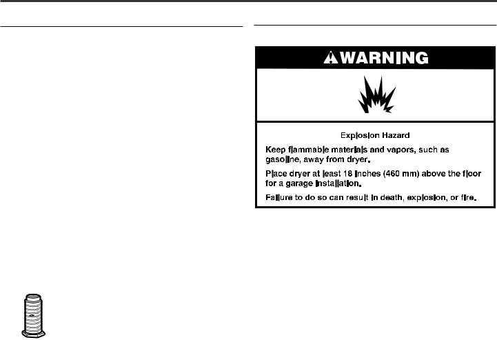
 WARNING
Explosion Hazard
Use a new CSA International approved gas supply line. Install a shut-off valve.
Securely tighten all gas connections.
If connected to LP, have a qualified person make sure gas pressure does not exceed 13" (330 mm) water column.
Examples of a qualified person include:
licensed heating personnel,
authorized gas company personnel, and authorized service personnel.
Failure to do so can result in death, explosion, or fire.
Gas type
Natural gas:
This dryer is equipped for use with Natural Gas. It is designcertified by CSA International for LP (propane or butane) gases with appropriate conversion.
■■ Your dryer must have the correct burner for the type of gas in your home. Burner information is located on the rating plate in the door well of your dryer. If this information does not agree with the type of gas available, please reference the “Assistance or Service” section of the “Dryer User Instructions.”
LP gas conversion:
Conversion must be made by a qualified technician.
No attempt shall be made to convert the dryer from the gas specified on the model/serial rating plate for use with a different gas without consulting the serving gas supplier.
IMPORTANT: The gas installation must conform with local codes, or in the absence of local codes, with the National Fuel Gas Code, ANSI Z223.1/NFPA 54 or the Canadian Natural Gas and Propane Installation Code, CSA B149.1.
Gas supply line
■■ 1/2" NPT pipe is recommended.
■■ 3/8" approved tubing is acceptable for lengths under 20 ft. (6.1 m) if local codes and gas supplier permit.
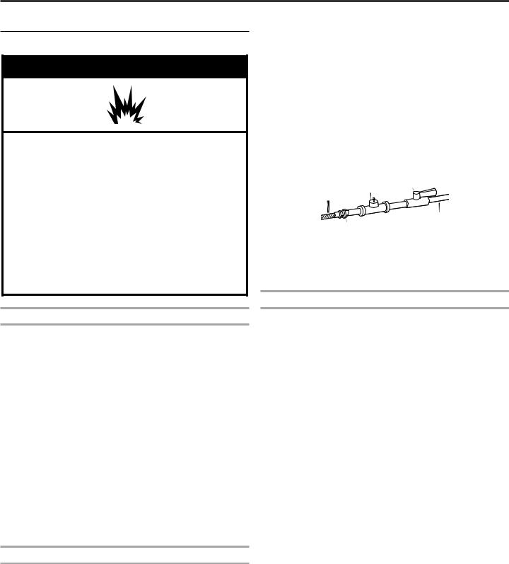
■■ Must include 1/8" NPT minimum plugged tapping accessible for test gauge connection, immediately upstream of the gas connection to the dryer (see illustration).
■■ Must include a shutoff valve:
In the U.S.A.:
An individual manual shutoff valve must be installed within six (6) feet (1.8 m) of the dryer in accordance with the National Fuel Gas Code, ANSI Z223.1.
In Canada:
An individual manual shutoff valve must be installed in accordance with the B149.1, Natural Gas and Propane Installation Code. It is recommended that an individual manual shutoff valve be installed within six (6) feet (1.8 m) of the dryer.
The shut off valve location should be easy to reach for opening and closing.
C E
A
D
B
A.3/8" flexible gas connector
B.3/8" pipe to flare adapter fitting
C.1/8" NPT minimum plugged tapping
D.1/2" NPT gas supply line
E.Gas shutoff valve
Gas supply connection requirements
There are many methods by which your gas dryer can be connected to the gas supply. Listed here are some guidelines for two different methods of connection.
Option 1 (Recommended Method)
Flexible stainless steel gas connector:
■■ If local codes permit, use a new flexible stainless steel gas connector (Design Certified by the American Gas Association or CSA International) to connect your dryer to the rigid gas supply line. Use an elbow and a 3/8" flare x 3/8" NPT adapter fitting between the stainless steel gas connector and the dryer gas pipe, as needed to prevent kinking.
Option 2 (Alternate Method)
Approved aluminum or copper tubing:
■■ Lengths over 20 ft. (6.1 m) can use 3/8" approved tubing (if codes and gas supplier permit).
■■ If you are using Natural Gas, do not use copper tubing.
■■ 3/8" flare x 3/8" NPT adapter fitting between dryer pipe and 3/8" approved tubing.
■■ Lengths over 20 ft. (6.1 m) should use larger tubing and a different size adapter fitting.
■■ If your dryer has been converted to use LP gas, 3/8" LP compatible copper tubing can be used. If the total length of the supply line is more than 20 ft. (6.1 m), use larger pipe.
NOTE: Pipe joint compounds that resist the action of LP gas must be used. Do not use TEFLON®† tape.
†®TEFLON is a registered trademark of E.I. Du Pont De Nemours and Company.
7
Dryer gas pipe
■■ The gas pipe that comes out through the rear of your dryer has a 3/8" male pipe thread.
29" Wide Model
1¼" (32 mm)
A |
9¼" |
|
(235 mm) |
A. 3/8" NPT dryer pipe
27" Wide Model
A
*6¼" (159 mm)
1½"  (38 mm)
Burner input requirements
Elevations up to 10,000 ft. (3,048 m):
■■ The design of this dryer is certified by CSA International for use at altitudes up to 10,000 ft. (3,048 m), above sea level at the B.T.U. rating indicated on the model/serial number plate. Burner input adjustments are not required when the dryer is operated up to this elevation.
Elevations above 10,000 ft. (3,048 m):
■■ When installed above 10,000 ft. (3,048 m) a 4% reduction of the burner B.T.U. rating shown on the model/serial number plate is required for each 1,000 ft. (305 m) increase in elevation.
Gas supply pressure testing
■■ The dryer must be disconnected from the gas supply piping system during pressure testing at pressures greater than 1/2 psi.
A. 3/8" NPT dryer pipe
Venting
Venting Requirements
 WARNING
Fire Hazard use a heavy metal vent.
Do not use a plastic vent. Do not use a metal foil vent.
Failure to follow these instructions can result in death or fire.
WARNING: To reduce the risk of fire, this dryer MUST BE EXHAUSTED OUTDOORS.
IMPORTANT: Observe all governing codes and ordinances. Dryer exhaust must not be connected into any gas vent, chimney, wall, ceiling, attic, crawlspace, or a concealed space of a building.
If using an existing vent system
■■ Clean lint from the entire length of the system and make sure exhaust hood is not plugged with lint.
■■ Replace any plastic or metal foil vent with rigid heavy metal vent or flexible metal vent.
■■ Review Vent system chart. Modify existing vent system if necessary to achieve the best drying performance. Only rigid or flexible metal vent shall be used for exhausting.
If this is a new vent system
Vent Material
■■ Use a heavy metal vent. Do not use plastic or metal foil vent.
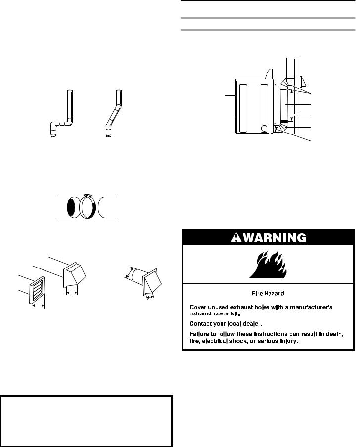
■■ 4" (102 mm) heavy metal exhaust vent and clamps must be used. DURASAFE™ venting products are recommended.
4" (102 mm) heavy metal exhaust vent
DURASAFE™ vent products can be purchased by calling the toll-free number. For further information, please reference the “Assistance or Service” section of the “Dryer User Instructions.”
Rigid metal vent:
■■ For best drying performance, rigid metal vents are recommended.
■■ Rigid metal vent is recommended to avoid crushing and kinking.
Flexible metal vent:
■■ Flexible metal vents are acceptable only if accessible for cleaning.
8
■■ Must be fully extended and supported when the dryer is in its final location.
■■ Remove excess flexible metal vent to avoid sagging and kinking that may result in reduced airflow and poor performance.
■■ Do not install flexible metal vent in enclosed walls, ceilings, or floors.
■■ The total length of flexible metal duct shall not exceed 7¾ ft. (2.4 m).
Elbows:
■■ 45° elbows provide better airflow than 90° elbows.
Good |
Better |
Clamps:
■■ Use clamps to seal all joints.
■■ Exhaust vent must not be connected or secured with screws or other fastening devices that extend into interior of duct and catch lint. Do not use duct tape.
Clamp |
|
Exhaust: |
|
Recommended hood styles. |
Acceptable hood style. |
B |
C |
|
4" |
A |
(102 mm) |
|
|
4" |
2½" |
(102 mm) |
(64 mm) |
4" |
|
(102 mm) |
|
A.Louvered hood style
B.Box hood style
C.Angled hood style is acceptable
■■ An exhaust hood should cap the vent to keep rodents and insects from entering the home.
■■ Exhaust hood must be at least 12" (305 mm) from the ground or any object that may be in the path of the exhaust (such as flowers, rocks or bushes, snow line, etc.).
■■ Do not use an exhaust hood with a magnetic latch.
Improper venting can cause moisture and lint to collect indoors, which may result in:
 Moisture damage to woodwork, furniture, paint, wallpaper, carpets, etc.
 Housecleaning problems and health problems.
Plan Vent System
Recommended exhaust installations
Typical installations vent the dryer from the rear of the dryer. Other installations are possible.
A
A.Dryer
B.Elbow
C.Wall
D.Exhaust hood
E.Clamps
B
 C
C
 D
D
E |
F |
G |
B
 I H
I H
F.Rigid metal or flexible metal vent
G.Vent length necessary to connect elbows
H.Exhaust outlet
I.Optional side exhaust outlet (27" wide models only)
Optional exhaust installations:
27" Wide Models can be converted to exhaust out the right side, left side, or through the bottom. Each kit includes step-by- step instructions. For further information, please reference the “Assistance or Service” section of the “Dryer User Instructions.”
9
 Loading...