


Essick Air AD1C71, AS1C7112, AD1C51, AD2C5112, AS1C71 User Manual
...
|
Models |
AD1C51 |
AD2C51 |
AS1C51 |
AS2C51 |
AD1C5112 |
AD2C5112 |
AS1C5112 |
AS2C5112 |
AD1C71 |
AD2C71 |
AS1C71 |
AS2C71 |
AD1C7112 |
AD2C7112 |
AS1C7112 |
AS2C7112 |
AU1C7112 |
AU2C7112 |
Read Carefully All Of This Manual
Before Installing The Unit
Lea Con Cuidado Todo Este Manual Antes De Instalar La Unidad
Circle the model of your cooler and record the serial number below.
Encierrre con un circulo el modelo de su enfriador y escribe el número de série abajo.
Serial #
Número De Série
Table Of Contents
Safety Instructions ....................................................................... |
1 |
Installation Instructions............................................................ |
2-3 |
Electrical Wiring Diagram ........................................................... |
3 |
Operation.................................................................................. |
3-4 |
Maintenance Section.................................................................... |
4 |
Troubleshooting ........................................................................... |
5 |
Warranty....................................................................................... |
5 |
Parts List (Down Discharge Units) .......................................... |
6-7 |
Parts List (Side Discharge Units)............................................. |
8-9 |
Parts List (Up Discharge Units)........................................... |
10-11 |
Specification Tables (Tablas de Especificaciones)..................... |
12 |
Instrucciones en Español ..................................................... |
12-16 |
Vea el Español en el interior.
Read And Save These Instructions
Safety Rules
1.Read instructions carefully.
2.Electrical hook up should be done by a qualified electrician, so that all electrical wiring will conform to your local standards.
3.Always DISCONNECT POWER and UNPLUG motor and pump inside the cooler before installing or performing any maintenance.
4.Motor and pump have a grounded, molded plug and an automatic thermal overload switch which will shut motor off when it overheats. The motor will restart automatically when it cools down.
 WARNING: To reduce the risk of fire or electric shock, do not use this fan with any “solid-state fan speed control device.”
Evaporative Cooling
Evaporative cooling is nature’s way of cooling. When air is moved over a wet surface, water is evaporated and heat is absorbed. When stepping out of swimming pool with the wind blowing, evaporative cooling makes you feel cool, even though the air may be warm.
This unit works on the same principle. Air is drawn across wet filter pads where the air is cooled by evaporation and then circulated throughout the building. It is this combination of cooled air and the movement of air over the skin which makes it feel cool.
Unlike refrigeration systems which recirculate the air, an evaporative cooler continually brings in fresh air while exhausting old air. You are completely replacing the air every 2 to 4 minutes by opening windows or doors or a combination of both. The air is always fresh, not stale, laden with smoke and odors as happens with refrigerated air conditioning.
110498-3 |
www.championcooler.com |
9-09 |
Cooler Installation
 CAUTION: Make sure that the mounting surface is strong enough to support the operating weight of the cooler when in use. (For operating weight, see Specification Table.)
 CAUTION: Never start cooler until installation is complete and unit has been tested for rigidity.
 CAUTION: Do not screw or drill within 5 inches of the bottom of the wet module. You could puncture the reservoir.
 CAUTION: If the unit is supported with legs at each corner, the middle of the unit where the two sec-
tions join must be supported as well.
|
Wet |
|
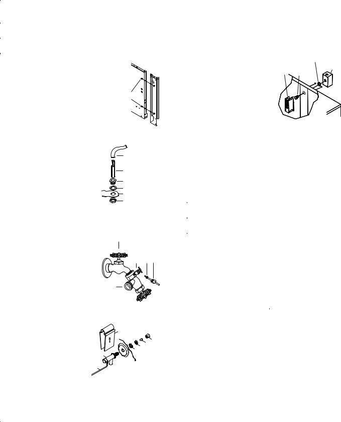
NOTE: For ease of installation you can |
Module |
|
separate the wet module from the blower |
Mounting |
|
module by removing the 4 bolts from the wet |
||
Bolts |
||
module side (Fig. 1). Remember to unplug |
|
|
the pump and drain pump before separating |
Fig. 1 |
|
the modules. |
Water Connection
•Install overflow assembly. Remove nut and place nipple through the hole in the pan, with the rubber washer between the pan and the head of the drain nipple (Fig. 2). Screw on nut and draw up tight against bottom of pan. Insert overflow into nipple to retain water. The overflow pipe comes from the factory connected to the dump pump hose. The overflow pipe may be removed to drain pan when necessary. A garden hose may be screwed on the drain nipple to drain water away from your unit.
Drain Pump
Hose
Overflow Pipe
Nipple
Rubber Washer
Bottom Pan
Nut
Fig. 2
•Connect water supply line. Install a sillcock and water valve on faucet as shown by figure 3. Place the nut and ferrule on the tubing and tighten the nut until water tight. NOTE: Do not connect the water supply to any soft water applications.
•Install float valve and fill pan.
Refer to Fig. 4. Remove items 1, 2, 3, and 4. Insert float body (5) through hole in back post panel as shown. Install washer (1) and nut
(2). Tighten to keep float from turning. Place nut (4) and ferrule (3) on water supply line. Connect to float fitting and tighten until water tight. Bend rod (6) to adjust float until water level is about 1 inch below the top of the overflow pipe. Slide float shield (7) over float body (5) until it snaps into place.
Faucet
SupplyWaterValveFerruleNut
Sillcock
Fig. 3
7
3 4
1 2
5
6
Fig. 4
Electrical Installation
 WARNING: Disconnect all electrical service that will be used for this unit before you begin the installation and leave it disconnected until the installation is complete.
The control box is factory wired and installed for either 120V or 230V operation depending on the model you purchased. The supply power
should be adequately protected against overloads and short circuits.
Note: Electrical installation should be performed by a qualified electrician. Be sure to follow all National and Local Electrical Codes when installing this cooler.
•Install weatherproof switch box. Located inside the unit in a plastic bag is a switch box and cover, a chase nipple, a seal ring and a toggle switch. Remove the electrical junction box (Fig. 5) which is mounted on the inside of the center panel. From inside the unit, insert the chase nipple
through the electrical access |
|
Seal Ring |
Electrical |
hole. Slide the seal ring over |
|
||
Junction |
Chase |
Box |
|
the chase nipple. Mount the |
Box |
Nipple |
|
switch box to the outside of the |
|
|
|
unit by threading the chase nip- |
|
|
|
ple into the switch box. Run |
|
|
|
the three switch leads through |
|
|
|
the nipple and into the switch |
|
|
|
box and reinstall the junction |
Fig. 5 |
|
|
box. Connect the green ground |
|
|
|
lead to the ground screw in the |
|
|
|
switch box. |
|
|
|
•Supply power to unit. Run power to the external switch box and connect to the two poles of the toggle switch. Connect the gray and white leads from the cooler electrical box to the two poles of the toggle switch. Refer to the appropriate wiring diagram to complete the electrical installation of your cooler. Secure the switch into the switch box and install the gasket and switch cover.
 CAUTION: All openings in the external switch box must be sealed to prevent water from entering the switch box.
 CAUTION: Pump receptacles are for grounded evaporative cooler pumps only. Do not plug anything else into receptacle.
 WARNING: Make sure that cooler cabinet is properly grounded to a suitable ground connection for maximum safety.
Thermostat Installation
1)Find a suitable location for the wall thermostat (away from sources of heat, sunlight, or ventilation, and between 4 and 6 feet from the floor). The thermostat may be mounted to a standard electrical box.
2)Route an insulated four-conductor thermostat cable (or similar) from the Control Box inside the cooler to the thermostat electrical box. This cable is not supplied.  WARNING: The thermostat cable should not be routed next to or enter the cabinet through the same inlet as the power supply wire.
3)Connect the thermostat wires to the terminals on the back of the wall control and to the terminals located on the left side of the control box in the unit. Make sure to follow the color code found next to each terminal.
Amperage Draw And Belt Tension
This unit is equipped with an adjustable motor drive sheave for adjusting the blower wheel speed to the proper loading on different duct systems. It is important that the motor drive pulley is adjusted to correct size to assure maximum air delivery without damage to the motor. Be sure to follow these instructions carefully.
•Adjust drive pulley. After the unit is completely installed, adjust the drive pulley to the least diameter and adjust belt tension. See the maintenance section for adjusting belt tension.
2 |
110498-3 |

•Start cooler. Install both inspection panels, start pump, and allow to operate until pads are wet.
•Check amperage. With pads wet and unit started, check amperage draw with an amperage meter.
•Adjust pulley if necessary. If amperage draw is less than motor rating, turn off electrical power and
remove inspection panels. Unplug motor inside cooler, this will protect you
from someone turning on unit while you are working inside. This should be done for your safety. Adjust pulley to a larger diameter and readjust belt tension, plug motor in, install inspection panels, and retest amperage draw. Repeat this
process until correct amperage draw is attained. Increasing motor pulley diameter increases amperage draw. Decreasing motor pulley diameter decreases amperage draw (see Fig. 6).
 CAUTION: Do not operate cooler with larger amperage draw than specified on motor plate.
Thermostat Operation
Automatic Operation (Cool Mode)
The fan and water pump are controlled automatically to achieve the desired comfort level.
This mode is activated by pressing the ‘Cool’ button. A blue LED is illuminated, and for a few seconds the LCD will display the ‘Set’ temperature. Pressing the ‘Cool’ button again deactivates this mode.
The Set temperature (the target temperature for control) may be altered by repeatedly pressing or holding the ‘Up’ and ‘Down’ buttons. The LCD will display ‘Set’ rather than ‘Room’ temperature for a short time after pressing the ‘Up’ or ‘Down’ button.
On starting, if the pads in the cooler are too dry, the fan may be delayed from starting until the pads have absorbed some water. This is called Pre-wet and lasts for 2 minutes, indicated by a flashing blue LED. Selecting ‘Fan’ and then ‘Cool’ will bypass the pre-wet and cause the fan and pump to start immediately. (If cooling is required).
During automatic operation, the control performs a 90 second water dump cycle every 8 or 12 hours of pump operation. This interval can be toggled between 8 or 12 hours by simultaneously holding the ‘Cool’ and ‘Fan’buttons for 5 seconds. The selected interval is displayed for a short time. This action also starts a manual dump cycle.
Ventilation Operation (Fan Mode)
The fan speed is set by the user, the water pump is turned off.
This mode is activated by pressing the ‘Fan’ button. A green LED is illuminated, and the LCD indicates fan speed. Pressing the ‘Fan’ button again deselects this mode.
Pressing the ‘Up’ button selects maximum Fan speed, and ‘Hi’ is displayed in the LCD; pressing the ‘Down’ button selects minimum Fan speed, and ‘Lo’ is displayed in the LCD.
Time Delay Operation (Timer Mode)
Delayed start or finish in ‘Cool’ or ‘Fan’ mode.
The ‘Timer’ button is used to set a delay period of 2, 4 or 8 hours, depending on how many times the button is pressed.
If the cooler is operating in ‘Cool’ or ‘Fan’ modes when the ‘Timer’ button is pressed, the delay period determines when the cooler will switch off. If the cooler is Off when the ‘Timer’ button is pressed, the delay period determines when the cooler switches on.
The starting mode is indicated by a flashing LED. You can change this mode by pressing the appropriate button (‘Cool’ or ‘Fan’).
You can cancel the Timer function at any time by pressing the ‘Timer’ button until all the timer LED’s go out.
In The Event Of A Power Outage
If the cooler is operating in ‘Cool’ or ‘Fan’ mode when power is interrupted, the cooler will resume in the same mode of operation when the power is restored.
If the cooler was in any ‘Timer’ mode at the time of a power interruption, the cooler will remain off when power is restored.
Wiring Diagrams
120 Volt
COOLER TERMINAL BOX
BLACK
RED
WHITE
GREEN
ORANGE
FAN MOTOR RECEPTACLE GREEN
WHITE
BLUE
ORANGE 
BROWN
GREEN
WHITE
BLUE
ORANGE 
BROWN
DRAIN PUMP
RECEPTACLE
TOGGLE SWITCH
SWITCH LEADS
|
GRAY |
|
120 VAC |
|
WHITE |
|
|
|
GREEN |
|
|
|
|
|
GROUND |
|
|
THERMOSTAT |
|
|
FAN |
PWR. SUPPLY |
PUMP DUMP |
BLACK |
FCom FHi FLo |
NLink N L1 LINK |
DCom DP PCom PP |
GRAY |
|
|
|
RED
YELLOW
BLUE
VIOLET
WHITE
 =WIRE NUT (11)
COOLER TERMINAL BOX
BLACK
RED
WHITE
GREEN
ORANGE
FAN MOTOR RECEPTACLE GREEN
WHITE
BLUE ORANGE BROWN
CIRCULATING PUMP
RECEPTACLE GREEN
WHITE
BLUE
ORANGE
BROWN
DRAIN PUMP
RECEPTACLE
240 Volt
TOGGLE SWITCH
SWITCH LEADS
|
GRAY |
|
|
240 VAC |
|
|
WHITE |
|
|
|
|
|
|
|
|
|
|
|
GREEN |
|
|
|
|
|
|
|
|
GROUND |
|
|
|
THERMOSTAT |
|||
|
FAN |
PWR. SUPPLY |
PUMP DUMP |
||
BLACK |
FCom FHi FLo |
NLink N L1 LINK |
DCom DP PCom PP |
||
GRAY |
|
|
|
|
|
RED
YELLOW
BLUE
VIOLET
WHITE
 =WIRE NUT (11)
110498-3 |
3 |
Required Exhaust Openings
An often misunderstood concept of evaporative cooling is the amount of air that should be exhausted. How much should you open your windows? The fact is that most people do not open their windows enough. The following two methods will help you determine the amount to open your windows.
First Method
You should allow an opening of at least 2 square feet (288 square inches) for each 1000 CFM rating of your unit. Example: At 3790 CFM, model AD1C51 (3/4 hp) requires 7.6 square feet (1094 square inches) of opening (3790/1000 * 2 = 7.6). Multiply the number of windows by window width in inches and divide this into the number of square inches required for your size unit. This will give you the height to open windows. In this example, four 36 inch wide windows should be opened 7.6 inches each.
Champion Air Balancing Method
1.Take a piece of tissue paper and cut it lengthwise into 3 equal strips.
2.Turn your cooler on high cool.
3.Open one window at least six inches wide in each room that you want to cool.
4.Take the piece of tissue paper and put it up against the screen of the open window furthest from the cooler discharge opening. Let go of it. It will do one of three things.
IF It falls down.
THEN CLOSE all of the windows one inch and try step 4 again.
IF It plasters itself to the screen.
THEN OPEN all of the windows one inch and try step 4 again.
IF It stays on the screen lightly.
THEN PERFECT. You are done. Enjoy your cooler.
NOTES:
•When switching to low cool, you must rebalance your home. Repeat step 4.
•Once you balance your home you can cool some areas more than others by opening those windows more and closing the others by the same amount. Repeat step 4 to make sure your home is still air balanced.
Maintenance
 WARNING : Before doing any maintenance be sure power is off. At the time you remove either inspection panel be sure to unplug motor and pumps. This is for your safety.
Spring Start-Up
•Clean pads. A clean pad is more absorbent, efficient and will give more cool air. Annually, or when required, using a garden hose with nozzle, back wash to clean out the openings, then clean off the inlet face any scale or other obstruction to the passages. Slight scraping may be required to remove hardened scale.
•Change pads if necessary. The pads should be replaced after 5 years or if necessary. To change pads, remove top access panel, remove grill, and disconnect water delivery tube. Remove water distributor holder and lift out media sections. Replace with the same type media. You can purchase them from your dealer.
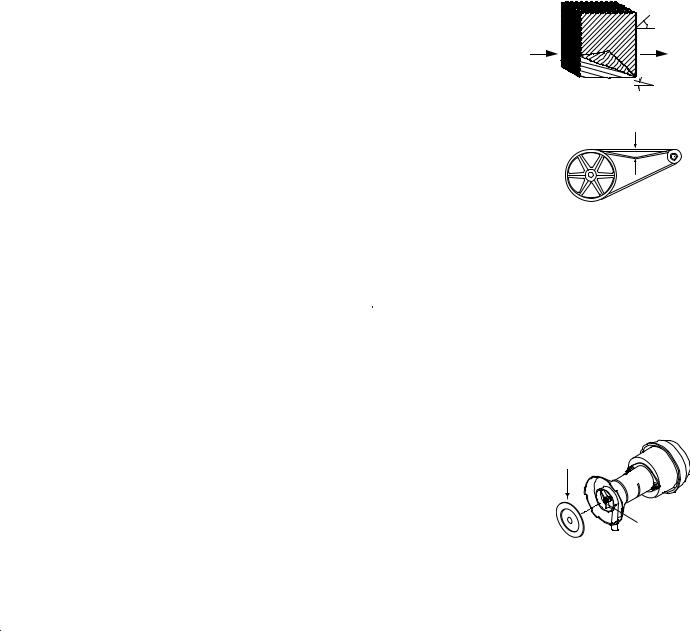
IMPORTANT: In order to get the best performance from your cooling pads, they must be installed properly. If you have purchased a pad with two equal angles, the following instructions can be disregarded. Pads must always be installed with the steeper flute angle sloping down
towards the air entering side (Fig. 7). The reason is simple. The steeper
angle puts more water on
the hot, dry, dirty side of the pad where it is needed
most. It also counteracts the tendency of the air to
push the water toward the back of the pad.
• Check belt tension. A 3 lb. force should deflect the belt 3/4 inches (see Fig. 8). Readjust belt if needed.
•Oil bearings. The blower bearings
and cooler motor in this unit should be oiled with a few drops of non-detergent 20/30 weight oil once each year. The motor does not need oil if it has no oil lines for oiling. Motors that have no oil lines are lifetime oiled at the factory and require no further oiling for the life of the unit.
 CAUTION: Do not over oil. Over oiling can cause motor burn out, due to excessive oil getting into motor winding.
•Clean water pump and dump pump. Cleaning both pumps is necessary once a year at start-up. For your safety, turn unit off and unplug motor and pumps. Remove the pump from the mount slot. Remove the base of the pump as shown in Fig. 9. Clean the pump and turn the impeller to ensure free operation. Remove the
pump spout and check for any blockage. After cleaning, reinstall
the base onto the pump. Press |
|
firmly to make sure it is secure. |
Remove |
Reattach the pump to the mount |
Base |
in the cooler using the plastic |
|
retainer to ensure that the pump |
|
will not overturn. Do not forget |
|
to replace the spout and water |
Impeller |
delivery tube onto the pump |
Fig. 9 |
outlet. |
Winter Shut-Down
•Drain water. Always drain all of the water out of the cooler and water supply line when not in use for prolonged periods, and particularly at the end of the season. Keep the water line disconnected from both the unit and water supply so that it does not freeze.
•Unplug motor and pumps. When cooler is not used for extended periods unplug the motor and pumps from inside cooler.
•Cover unit. To protect the life of the finish, a cover for the unit is suggested in extended periods of non use.
By following the operating, installation, and maintenance suggestions as outlined, you can get many years of efficient and satisfactory service from your cooler. In the event additional information is desired, your dealer will be more than glad to assist you in every possible way.
4 |
110498-3 |

Troubleshooting Guide
Problem |
Possible Cause |
|
Remedy |
|
Failure to |
1. No electrical power |
1. |
Check power |
|
start or no air |
|
to unit |
|
|
delivery/ No |
•Fuse blown |
• Replace fuse |
||
LCD display |
•Circuit breaker tripped |
• Re-set breaker |
||
|
2. |
Motor overheated |
2. |
Determine cause |
|
•Belt too tight |
• Adjust belt tension |
||
|
•Blower bearings dry |
• Oil blower bearings |
||
|
•Motor pulley diameter |
• Adjust pulley to correct |
||
|
|
too large |
|
diameter |
|
3. |
Motor locked |
3. |
Replace motor |
|
4. |
Fuse blown in unit |
4. |
Replace Fuse |
|
|
control box |
|
|
|
5. |
Incorrect wiring be- |
5. |
Check that wiring is correct |
|
|
tween wall thermostat |
|
and secured to terminals |
|
|
and cooler |
|
|
|
6. |
Poor connection to |
6. |
Check connections to termi- |
|
|
Fan motor terminals |
|
nal |
|
7. |
Unit control board or |
7. |
Supply power to control box |
|
|
wall thermostat faulty |
|
and check DC voltage at |
|
|
|
|
wall thermostat |
|
|
|
• If voltage between Black |
|
|
|
|
|
& Red terminals is close to |
|
|
|
|
3.5VDC and LCD is blank |
|
|
|
|
- wall thermostat is faulty |
|
|
|
• If voltage is much less than |
|
|
|
|
|
3.5VDC, remove red wire |
|
|
|
|
from terminal. If voltage |
|
|
|
|
rises to 3.5VDC - thermostat |
|
|
|
|
is faulty. If voltage remains |
|
|
|
|
low - unit control board is |
|
|
|
|
faulty. |
|
|
|
|
|
Inadequate |
1. Insufficient air exhaust |
1. |
Open windows or doors to |
|
air delivery |
|
|
|
increase air flow |
with cooler |
2. Belt too loose |
2. Adjust belt tension or |
||
running |
|
|
|
replace if needed |
|
3. |
Pads plugged |
3. |
Clean pads |
|
4. |
Motor underloaded |
4. Adjust pulley |
|
Problem |
Possible Cause |
|
Remedy |
|
Water drain- |
1. |
Float arm not adjusted |
1. Adjust float |
|
ing onto roof |
|
properly |
|
|
|
2. |
Overflow assembly |
2. Tighten nut and overflow |
|
|
|
leaking |
|
pipe |
|
|
|
|
|
Musty or |
1. |
Stale or stagnate water |
1. |
Drain pan and clean pads |
unpleasant |
|
in cooler |
|
|
odor |
|
|
|
|
|
|
|
|
|
Motor cycles |
1. |
Low voltage |
1. |
Check voltage |
on and off |
2. |
Excessive belt tension |
2. Adjust belt tension |
|
|
3. |
Blower shaft tight or |
3. |
Oil or replace bearings |
|
|
locked |
|
(Unplug unit) |
|
4. |
Bearings dry |
4. |
Oil bearings |
|
5. |
Motor pulley diameter |
5. Adjust pulley so full load |
|
|
|
too large causing motor |
|
ampere rating of motor is |
|
|
overload |
|
not exceeded |
|
|
|
|
|
Noisy |
1. |
Bearings dry |
1. |
Oil bearings |
|
2. Wheel rubbing blower |
2. |
Inspect and realign (Un- |
|
|
|
housing |
|
plug unit) |
|
3. |
Loose parts |
3. Tighten loose parts |
|
|
|
|
|
|
Inadequate |
1. |
Inadequate exhaust in |
1. |
Open windows or doors to |
cooling |
|
house |
|
increase air flow |
|
2. |
Pads not wet |
2. |
Check water distribution |
|
|
|
|
system |
|
•Pads plugged |
• Clean pads |
||
|
•Dist. tube holes clogged |
• Clean |
||
|
•Pump not working prop- |
• Replace or clean pump |
||
|
|
erly |
|
(Unplug unit) |
|
3. |
Poor connection to Pump |
3. |
Check connections |
|
|
terminals on Control |
|
|
|
|
Board |
|
|
|
|
|
|
|
Excessive |
1. |
Insufficient air exhaust |
1. |
Open doors or windows |
humidity in |
|
|
|
|
house |
|
|
|
|
Register your product online at www.championcooler.com/eac/onlineregistration-eac.htm
Limited Warranty
This warranty is extended to the original purchaser of an evaporative cooler installed and used under normal conditions. It does not cover damages incurred through accident, neglect, or abuse by the owner. We do not authorize any person or representative to assume for us any other or different liability in connection with this product.
Terms And Conditions Of Warranty
Lifetime Limited Coverage on water reservoir against any leakage due to defects in material. From date of purchase, if any original component part provided by Champion Cooler fails due to defect in material or factory workmanship only, we will provide the replacement part as follows:
One year on the cabinet components.
Five years on the evaporative media.
Two years on the original blower motor if furnished by Champion Cooler.
Exclusions From The Warranty
We are not responsible for any incidental or consequential damage resulting from any malfunction.
We are not responsible for any damage received from the use of water softeners, chemicals, descale material, plastic wrap, or if a motor of a higher horsepower than what is shown on the serial plate is used in the unit.
We are not responsible for the cost of service calls to diagnose cause of trouble, or labor charge to repair and/or replace parts.
How To Obtain Service Under This Warranty
Contact the Dealer where you purchased the evaporative cooler. If for any reason you are not satisfied with the response from the dealer, contact the Customer Service Department: Champion Cooler, 5800 Murray Street, Little Rock, Arkansas 72209. 1-800-643-8341. E-mail: info@championcooler.com.
This limited warranty applies to original purchaser only.
110498-3 |
5 |
 Loading...