

Ergotron StyleView SV41, StyleView SV42 LiFe, StyleView SV42 SLA, StyleView SV31, StyleView SV32 User Manual
Page 1
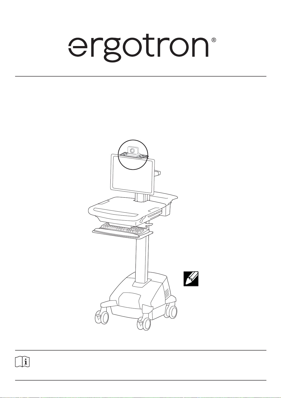
User's Guide
StyleView® Camera Shelf
For the latest User Installation Guide please visit: www.ergotron.com
English, Español, Français, Deutsch, Nederlands, Italiano, Svenska, 日本語, 汉语
www.ergotron.com |
888-97-320-W-00 rev. B • 08/19
USA: 1-800-888-8458
|
Europe: +31 (0)33-45 45 600
|
China: 400-120-3051
|
NOTE: camera is
supplied by customer.
English
Japan: japansupport@ergotron.com
1 of 7
Page 2
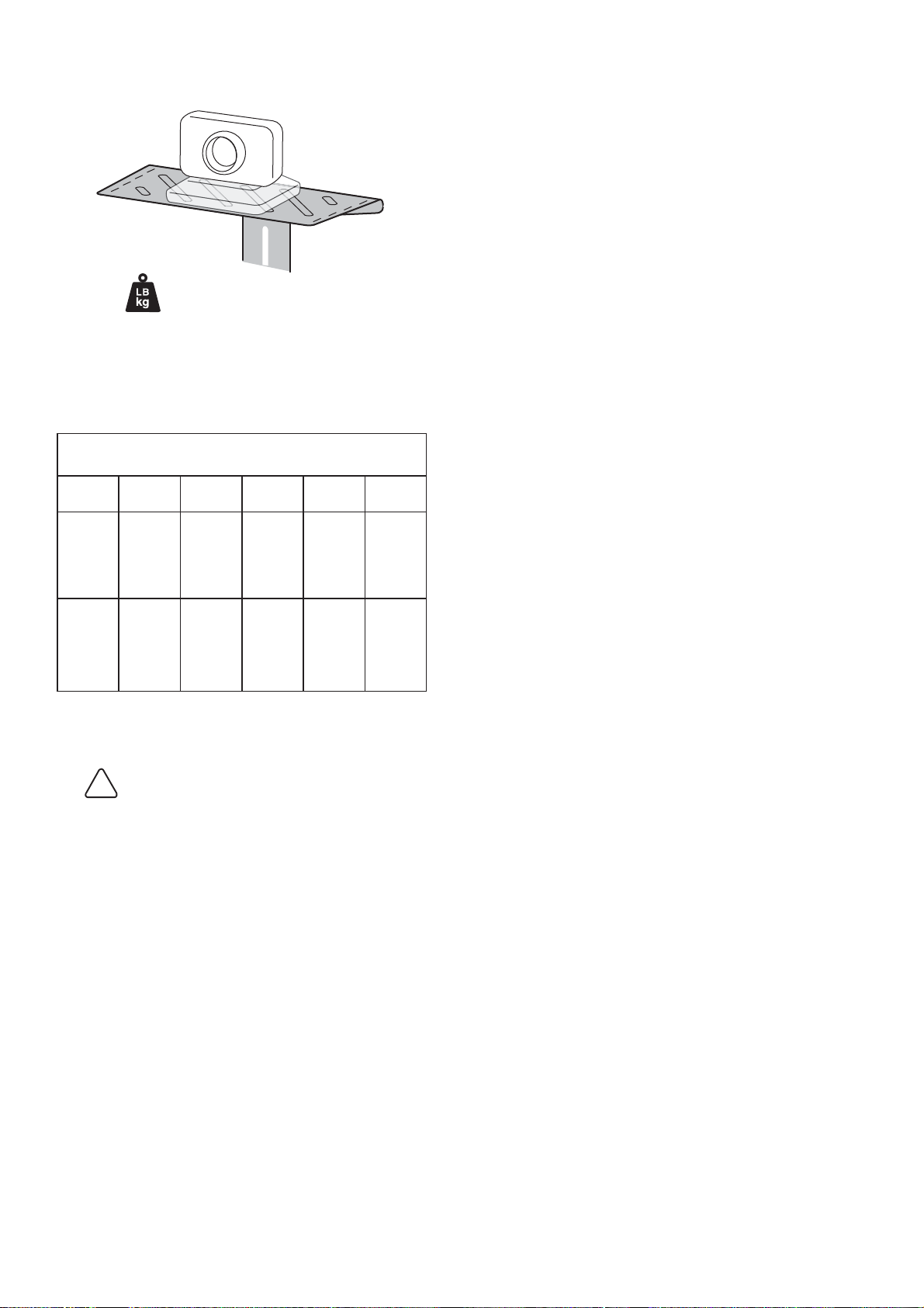
Features & Specifi cations
Max weight: 2 lbs (1 kg)
Weight Capacity Limitations for Carts
with Added Camera Shelf
LCD Arm
or 5” Lift
Pivot
without
lock-out
SV41
10 lbs.
(4.5 kg)
SV42
SLA
10 lbs.
(4.5 kg)
SV42
LiFe
7 lbs. (3.2
kg)
SV31 SV32
12 lbs.
(5.4 kg)
12 lbs.
(5.4 kg)
5” Lift with
lock-out
16 lbs.
(7.3 kg)
16 lbs.
(7.3 kg)
16 lbs.
(7.3 kg)
16 lbs.
(7.3 kg)
CAUTION: Do Not Exceed Maximum Listed Weight
Capacity. Failure to heed this caution may cause serious
Injury or property damage to occur.
16 lbs.
(7.3 kg)
2 of 7
888-97-320-W-00 rev. B • 08/19
Page 3
1/4”
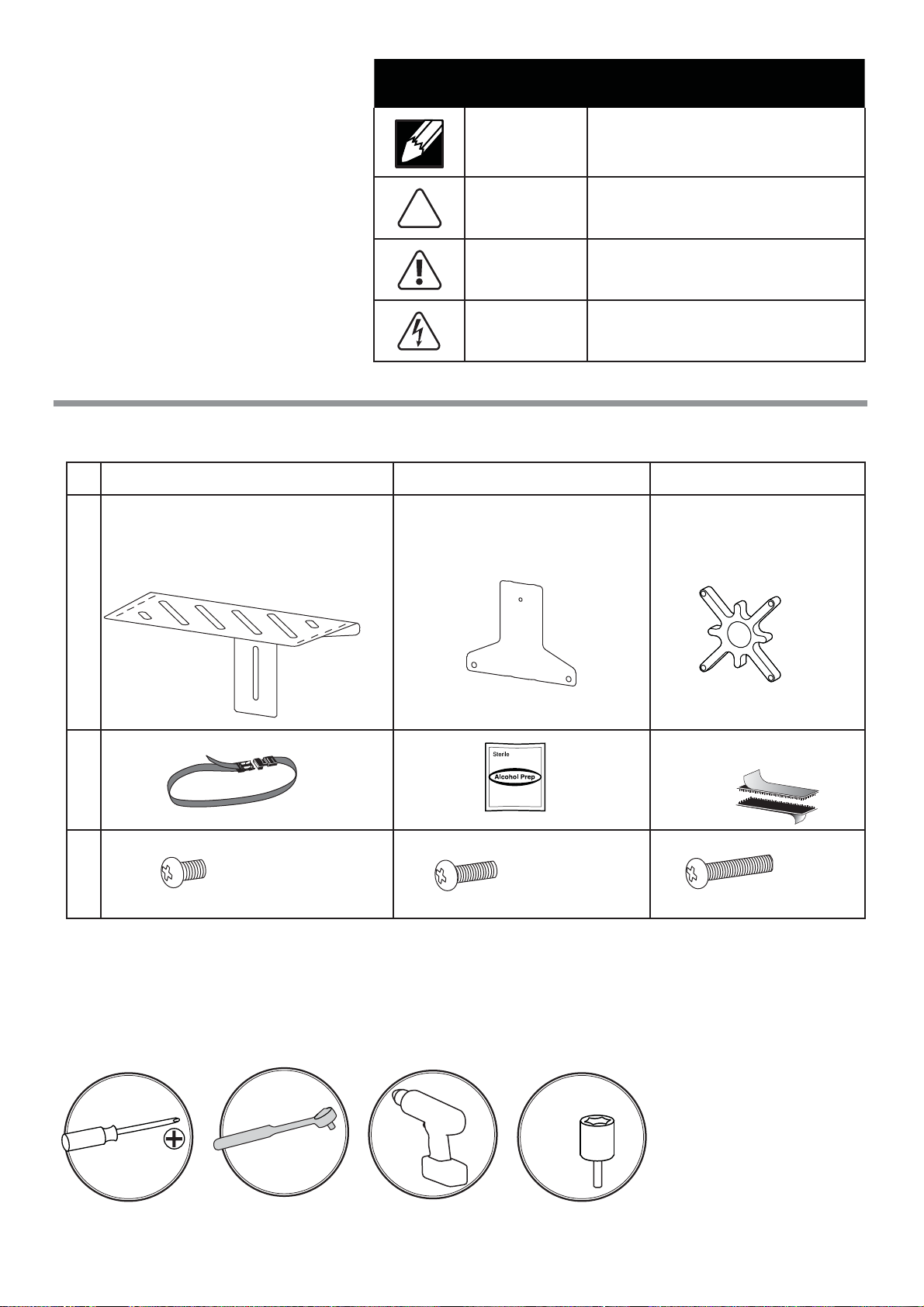
Hazard Symbols Review
Symbol Signal Word Level of Hazard
These symbols alert users of a safety condition that
demands attention. All users should be able to
recognize and understand the signi cance of the following Safety Hazards if encountered on the product
or within the documentation. Children who are not
able to recognize and respond appropriately to Safety
Alerts should not use this product without adult
supervision!
Components
ABC
1x 1x 1x
NOTE
CAUTION
WARNING
ELECTRICAL
A NOTE indicates important information that helps you
make better use of this product.
A CAUTION indicates either potential damage to
hardware or loss of data and tells you how to avoid the
problem.
A WARNING indicates either potential for property damage, personal injury, or death.
An Electrical indicates an impending electrical hazard
which, if not avoided, may result in personal injury, re
and/or death.
1
2
3
1x
Tools Needed
M4 x 6mm
2x
M4 x 14mm
1x1x1x
4x
M4 x 25mm
888-97-320-W-00 rev. B • 08/19
14mm
3 of 7
Page 4

CAUTION: Do Not Exceed Maximum SV LCD Cart Weight Capacity 35 lbs. (16 kg). This is
the sum of LCD monitor, CPU, keyboard/mouse, camera and any worksurface load, including drawers, if present. Failure to heed this caution may cause serious Injury or property damage to occur.
1
a. Attach shelf to
bracket using the
provided M4x6mm
Phillips screw.
If your monitor has recessed mounting holes,
you need to add the provided spacer between
the monitor and the mounting plate.
a. Remove the monitor from the cart and set aside on a clean and level surface.
The monitor screws can be discarded.
b. Attach the spacer to the monitor with the four provided M4x25mm Phillips screws.
1x
M4 x 6mm
c. Reattach the monitor to the cart.
d. When following step 2 instructions on next page, DO NOT discard the M4x25mm
screws. The should be used to mount the shelf/bracket assembly.
4 of 7
888-97-320-W-00 rev. B • 08/19
Page 5

a. Remove the top, left screw and discard. (If using spacer, do not discard the screw!)
2
b. Slip the shelf/bracket assembly behind the monitor plate and insert one of the provided
M4x14mm Phillips screw into the top, left hole. (If using spacer, reinsert the M4x25mm
screw removed in step 2a, above.) Allow screw to be secure but not tight.
c. Remove the top, right screw and discard. (If using spacer, do not discard the screw!)
d. Slip the other end of the shelf/bracket assembly behind the monitor plate and insert a
M4x14mm Phillips screw into the top, right hole. (If using spacer, reinsert the M4x25mm
screw removed in step 2c, above.) Tighten both top screws.
a
c
b
d
2x
M4 x 14mm
2x
M4 x 14mm
888-97-320-W-00 rev. B • 08/19
5 of 7
Page 6

3
3 Mounting Options
a
b
a
b
c
6 of 7
d
888-97-320-W-00 rev. B • 08/19
Page 7

4
Adjustment Step
Lift – Up and down
bc
Once the camera has been mounted to the shelf, it is important that
you adjust the lift tension for the additional weight. Test the lift tension
by moving the head unit up and down. If it travels smoothly and easily
through the full range of motion, and does not drift up or sag down from
the place you set it, the tension is good. If not, adjust as directed below:
To change lift tension:
a. Remove cap.
b. Turn adjustment nut with a 14mm (9/16”) socket head.
c. Test lift tension by lifting head unit up and down.
d. When desired lift tension has been achieved, replace cap.
14mm (9/16")
NOTE: Adjustment
may require 40 - 60
revolutions.
For Warranty visit: www.ergotron.com/warranty
For Service visit: www.ergotron.com
For local customer care phone numbers visit: http://contact.ergotron.com
www.ergotron.com |
© 2013 Ergotron, Inc. All rights reserved.
888-97-320-W-00 rev. B • 08/19
USA: 1-800-888-8458
|
Europe: +31 (0)33-45 45 600
|
China: 400-120-3051
|
Japan: japansupport@ergotron.com
7 of 7
 Loading...