


 Loading...
SERVICE MANUAL
Color Inkjet Printer
EPSON WF-2540/WF-2548/WF-2541
EPSON WF-2530/WF-2532/WF-2538/WF-2531 EPSON WF-2520/WF-2528/WF-2521
EPSON WF-2510/WF-2511/WF-2512 EPSON WF-2010
CONFIDENTIAL
SEMF12-003
Notice:
All rights reserved. No part of this manual may be reproduced, stored in a retrieval system, or transmitted in any form or by any means, electronic, mechanical, photocopying, recording, or otherwise, without the prior written permission of SEIKO EPSON CORPORATION.
All effort have been made to ensure the accuracy of the contents of this manual. However, should any errors be detected, SEIKO EPSON would greatly appreciate being informed of them.
The contents of this manual are subject to change without notice.
The above not withstanding SEIKO EPSON CORPORATION can assume no responsibility for any errors in this manual or the consequences thereof.
EPSON is a registered trademark of SEIKO EPSON CORPORATION.
Note :Other product names used herein are for identification purpose only and may be trademarks or registered trademarks of their respective owners. EPSON disclaims any and all rights in those marks.
Copyright © 2012 SEIKO EPSON CORPORATION
Printer CS Quality Assurance Department
Confidential
Safety Precautions
All safety procedures described here shall be strictly adhered to by all parties servicing and maintaining this product.
DANGER
Strictly observe the following cautions. Failure to comply could result in serious bodily injury or loss of life.
1.Always disconnect the product from the power source and peripheral devices when servicing the product or performing maintenance.
2.When performing works described in this manual, do not connect to a power source until instructed to do so. Connecting to a power source causes high voltage in the power supply unit and some electronic components even if the product power switch is off. If you need to perform the work with the power cable connected to a power source, use extreme caution to avoid electrical shock.
WARNING
Strictly observe the following cautions. Failure to comply may lead to personal injury or loss of life.
1.Always wear protective goggles for disassembly and reassembly to protect your eyes from ink in working. If any ink gets in your eyes, wash your eyes with clean water and consult a doctor immediately.
2.When using compressed air products; such as air duster, for cleaning during repair and maintenance, the use of such products containing flammable gas is prohibited.
PRECAUTIONS
Strictly observe the following cautions. Failure to comply may lead to personal injury or damage of the product.
1.Repairs on Epson product should be performed only by an Epson certified repair technician.
2.No work should be performed on this product by persons unfamiliar with basic safety knowledge required for electrician.
3.The power rating of this product is indicated on the serial number/rating plate. Never connect this product to the power source whose voltages is different from the rated voltage.
4.Replace malfunctioning components only with those components provided or approved by Epson; introduction of second-source ICs or other non-approved components may damage the product and void any applicable Epson warranty.
5.The capacitors on the Main Board may be electrically charged right after the power turns off or after driving motors which generates counter electromotive force such as when rotating the PF Roller or when moving the CR Unit. There is a risk to damage the Main Board if the Head FFC is short-circuited with the capacitors on the Main Board electrically charged, therefore, after the power turns off or after motors are driven, leave the printer untouched for approximately 30 seconds to discharge the capacitors before starting disassembly/ reassembly.
6.To prevent the circuit boards from short-circuiting, be careful about the following when handling FFC or cables.
When handling FFC, take care not to let the terminal section of FFC touch metal parts.
When connecting cables/FFC to the connectors on circuit boards, connect them straight to the connectors to avoid slant insertion.
Confidential
7.In order to protect sensitive microprocessors and circuitry, use static discharge equipment, such as anti-static wrist straps, when accessing internal components.
8.Do not tilt this product immediately after initial ink charge, especially after performing the ink charge several times. Doing so may cause ink to leak from the product because it may take some time for the waste ink pads to completely absorb ink wasted due to the ink charge.
9.Never touch the ink or wasted ink with bare hands. If ink comes into contact with your skin, wash it off with soap and water immediately. If you have a skin irritation, consult a doctor immediately.
10.When disassembling or assembling this product, make sure to wear gloves to avoid injuries from metal parts with sharp edges.
11.Use only recommended tools for disassembling, assembling or adjusting the printer.
12.Observe the specified torque when tightening screws.
13.Be extremely careful not to scratch or contaminate the following parts.
Nozzle plate of the Printhead
CR Scale
PF Scale
Coated surface of the PF Roller
Gears
Rollers
LCD
Scanner Sensor
Exterior parts
14.Never use oil or grease other than those specified in this manual. Use of different types of oil or grease may damage the component or give bad influence on the printer function.
15.Apply the specified amount of grease described in this manual.
16.Make the specified adjustments when you disassemble the printer.
17.When cleaning this product, follow the procedure described in this manual.
18.When transporting this product after filling the ink in the printhead, pack the printer without removing the ink cartridges in order to prevent the printhead from drying out.
19.Make sure to install antivirus software in the computers used for the service support activities.
20.Keep the virus pattern file of antivirus software up-to-date.
21.When disassembling/reassembling this product, if you find adhesive power of the double-sided tape which secure the parts or FFC is not enough, replace the tape with new one and attach it correctly to the specified points where the parts or FFC should be secured.
22.Unless otherwise specified in this manual, the labels attached on the returned product should be transferred to the corresponding attachment positions on the new one referring to the labels on the returned product.
Confidential

About This Manual
This manual, consists of the following chapters, is intended for repair service personnel and includes information necessary for properly performing maintenance and servicing the product.
CHAPTER 1. TROUBLESHOOTING
Describes the step-by-step procedures for the troubleshooting.
CHAPTER 2. DISASSEMBLY / REASSEMBLY
Describes the disassembly/reassembly procedures for main parts/units of the product, and provides the standard operation time for servicing the product.
CHAPTER 3. ADJUSTMENT
Describes the required adjustments for servicing the product.
CHAPTER 4. MAINTENANCE
Describes maintenance items and procedures for servicing the product.
CHAPTER 5. REFURBISHMENT
Describes refurbishing work of the product and its purpose.
CHAPTER 6. APPENDIX
Provides the following additional information for reference:
•Connector Diagram
•Protection for Transportation
Symbols Used in this Manual
Various symbols are used throughout this manual either to provide additional information on a specific topic or to warn of possible danger present during a procedure or an action. Pay attention to all symbols when they are used, and always read explanation thoroughly and follow the instructions.
Indicates an operating or maintenance procedure, practice or condition that, if not strictly observed, could result in serious injury or loss of life.
Indicates an operating or maintenance procedure, practice, or condition that, if not strictly observed, could result in bodily injury, damage or malfunction of equipment.
May indicate an operating or maintenance procedure, practice or condition that is necessary to accomplish a task efficiently. It may also provide additional information that is related to a specific subject, or comment on the results achieved through a previous action.
For Chapter 2 “Disassembly/Reassembly”, symbols other than indicated above are used to show additional information for disassembly/reassembly. For the details on those symbols, see "2.2 Disassembly/Reassembly Procedures (p27)".
Confidential

Revision Status
Revision |
Date of Issue |
Description |
|
|
|
A |
June 29, 2012 |
First Release |
|
|
|
B |
August 28, 2012 |
Revised Contents |
|
|
□ Chapter 2 |
|
|
■ Made change in "2-1 Standard Operation Time (p24)" |
|
|
□ Chapter 3 |
|
|
■ Made change in "3-2 Required Adjustment List (p56)" |
|
|
■ Made change in "3.2.2.3 PIS Board Check (p62)" |
|
|
|
Confidential

WF-2540 / WF-2530 / WF-2520 / WF-2510 /WF-2010 series |
Revision B |
Contents
Chapter 1 Troubleshooting
1.1 |
Troubleshooting....................................................................................................................................................... |
10 |
|
|
1.1.1 Troubleshooting Workflow ............................................................................................................................ |
10 |
|
1.2 |
Power-On Sequence ................................................................................................................................................ |
12 |
|
1.3 |
Fatal Error Code List............................................................................................................................................... |
14 |
|
|
1.3.1 |
Displaying the Fatal Error Code..................................................................................................................... |
14 |
|
1.3.2 |
Printer Fatal Error Code ................................................................................................................................. |
15 |
|
1.3.3 |
Scanner Fatal Error Code ............................................................................................................................... |
18 |
Chapter 2 Disassembly/Reassembly
2.1 |
Overview |
.................................................................................................................... ............................................. |
20 |
|
|
2.1.1 |
Tools ............................................................................................................................................................... |
20 |
|
|
2.1.2 |
Jigs .................................................................................................................................................................. |
|
20 |
|
2.1.2.1 ..................................................................................................................Making the Spring Hook Jig |
20 |
||
|
2.1.3 |
Locations ...........................................................................................................................of the Parts/Units |
21 |
|
|
2.1.4 |
Standard ......................................................................................Operation Time for Servicing the Product |
24 |
|
2.2 |
Disassembly/Reassembly .....................................................................................................................Procedures |
27 |
||
|
2.2.1 |
Configuration.................................................................................................................................................. |
27 |
|
|
2.2.2 |
Disassembly ...................................................................................................................................Flowchart |
28 |
|
|
2.2.2.1 ....................................................................................................... |
Multifunction Printer specific parts |
30 |
|
|
2.2.2.2 ...................................................................................................... |
Singlefunction Printer specific parts |
32 |
|
|
2.2.2.3 .................................................................................................................Common Printer Mechanism |
34 |
||
|
2.2.2.4 ............................................................................................................................................... |
Unit/Assy |
36 |
|
|
2.2.3 |
Disassembly ...........................................................................................Flowchart (Printhead/Main Board) |
39 |
|
2.3 |
Detailed Disassembly/Reassembly ...........................................................................Procedure for each Part/Unit |
40 |
||
2.4 |
Routing FFCs/cables ............................................................................................................................................... |
48 |
||
Chapter 3 Adjustment
3.1 |
Required Adjustments ............................................................................................................................................. |
53 |
|
3.2 |
Adjustment Program................................................................................................................................................ |
60 |
|
|
3.2.1 Operating Environment .................................................................................................................................. |
60 |
|
|
3.2.2 Details of the Adjustment Program ................................................................................................................ |
60 |
|
|
3.2.2.1 |
CR Motor Heat Protection Control / PF Motor Heat Protection Control .............................................. |
60 |
|
3.2.2.2 |
Scanner Motor Heat Protection Control ................................................................................................ |
61 |
|
3.2.2.3 PIS Board Check.................................................................................................................................... |
62 |
|
3.3 |
Mechanism Adjustment / Check ............................................................................................................................. |
63 |
|
|
3.3.1 Checking the Platen Gap ................................................................................................................................ |
63 |
|
|
3.3.2 CR/PF Belt Tension Check............................................................................................................................. |
65 |
|
Chapter 4 Maintenance
4.1 |
Overview ................................................................................................................................................................. |
68 |
|
|
4.1.1 |
Cleaning.......................................................................................................................................................... |
68 |
|
4.1.2 |
Lubrication...................................................................................................................................................... |
68 |
4.2 |
Lubrication Points and Instructions......................................................................................................................... |
69 |
|
Chapter 5 Refurbishment
5.1 Overview ................................................................................................................................................................. |
74 |
5.1.1 Ink Discharge.................................................................................................................................................. |
74 |
7
Confidential

WF-2540 / WF-2530 / WF-2520 / WF-2510 /WF-2010 series |
Revision B |
|
Chapter 6 Appendix |
|
|
6.1 |
Connector Diagram ........................................................................................................... |
...................................... 76 |
6.2 |
Protection for Transportation .................................................................................................................................. |
77 |
|
6.2.1 Securing the CR Unit...................................................................................................................................... |
77 |
|
6.2.2 Securing the Paper Support/Paper Support Sub ............................................................................................. |
78 |
8
Confidential

CHAPTER 1
TROUBLESHOOTING
Confidential
WF-2540 / WF-2530 / WF-2520 / WF-2510 / WF-2010 series |
Revision B |
1.1 Troubleshooting
This section describes the troubleshooting workflow and fatal error information.
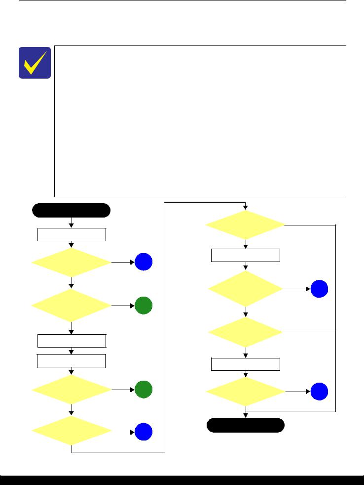
1.1.1 Troubleshooting Workflow
The following page describes the troubleshooting workflow. Follow the flow when troubleshooting problems.
In this chapter, the product names are called as follows:
•WF-2540 Series: WF-2540/WF-2548/WF-2541
•WF-2530 Series: WF-2530/WF-2532/WF-2538/WF-2531
•WF-2520 Series: WF-2520/WF-2528/WF-2521
•WF-2510 Series: WF-2510/WF-2511/WF-2512
•WF-2010 Series: WF-2010
This flowchart is compiled based on the following contents.
•Our experience regarding the quality problem.
•ESK’s repair data.
•Printer Mechanism specification for the product.
WF-2510 series are not equipped with the ADF unit, therefore, the troubleshooting related to the ADF unit is not applied.
WF-2010 series are not equipped with the ADF/Scanner unit, therefore, the troubleshooting related to the ADF/Scanner unit is not applied.
If the reason for the return is evident, first check the phenomenon user claims recurs, then proceed to the troubleshooting.
Start
Turn on the power*1
Does printer turn on the power?
Yes
Is Power-on sequence finished without error?
Standby condition
Print check pattern
Does an error occur when printing?
No
Is printing operation finished without trouble?
Yes
|
What is returned reason? |
Printer failure only |
||
|
|
|
||
|
ADF/Scanner failure |
|
||
No |
Copy an image |
|
|
|
1 |
|
|
|
|
(p 11) |
|
|
|
|
|
Is scanning operation |
No |
5 |
|
|
finished without |
|
||
No |
trouble? |
|
|
|
|
|
(p 11) |
||
2 |
|
|
||
Yes |
|
|
||
|
|
|
||
(p 11) |
|
|
|
|
|
|
No |
|
|
|
ADF failure? |
|
|
|
|
Copy an image by ADF |
|
|
|
Yes |
Is ADF operation |
No |
|
|
3 |
6 |
|||
finished without |
|
|||
(p 11) |
trouble? |
|
|
|
|
|
(p 11) |
||
|
Yes |
|
||
|
|
|
||
No |
4 |
Finish*2 |
|
*1: If the Hopper of ASF on the returned product touches the LD Roller, the |
|
|
|
|
|
(p 11) |
initial ink charge has not been completed for the product yet. |
|
|
*2: In case of “Not Trouble Found”, check fatal error code. |
Figure 1-1. Troubleshooting Workflow (1)
Troubleshooting |
Troubleshooting Workflow |
10 |
Confidential
WF-2540 / WF-2530 / WF-2520 / WF-2510 / WF-2010 series |
Revision B |
|||
1 |
The power-on sequence |
2 |
Error is indicated during power-on |
|
does not start (p 10) |
sequence(p 10) |
|
||
|
|
|
||
|
No Power* |
|
Fatal error |
[Presumable Cause] |
Please refer to " 1.3 Fatal Error |
||
• |
PS Unit damage |
Code List (p14)". |
|
• |
Main Board damage |
|
|
|
|||
[Major Troubleshooting]
•PS Unit replacement
•Main Board replacement
*: If the printer can turn on but turns off right away, the protection circuit may cut off the power due to an error such as a circuit failure.
|
Maintenance error |
|
|
Ink End error |
|
|
Ink Cartridge error |
|
|
No Ink Cartridge error |
|
|
Paper Jam Fatal error |
[Occurrence Condition] |
|
[Occurrence Condition] |
|
[Occurrence Condition] |
|
[Occurrence Condition] |
|
[Occurrence Condition] |
|||||
This error occurs when |
|
This error occurs when ink in Ink |
|
This error occurs when the Ink |
|
This error occurs when Ink |
|
This error occurs when CR Unit is |
|||||
maintenance counter in EEPROM |
|
Cartridge is empty. |
|
Cartridge failed. |
|
Cartridge is not installed. |
|
blocked by jammed paper. |
|||||
exceeds the specified value. |
|
[Major Occurrence Timing] |
|
[Major Occurrence Timing] |
|
[Major Occurrence Timing] |
|
[Major Occurrence Timing] |
|||||
[Major Occurrence Timing] |
|
|
|
|
|||||||||
|
• |
Power-on timing |
|
• |
Power-on timing |
|
• |
Power-on timing |
|
• |
Power-on timing |
||
• |
Power-on timing |
|
• |
Print start timing |
|
• |
Print start timing |
|
[Troubleshooting] |
|
[Major Troubleshooting]Åz |
||
• |
Print start timing |
|
• |
Cleaning timing |
|
• |
Cleaning timing |
|
|
||||
• |
Cleaning timing |
|
• |
Ink Cartridge replacement |
|
• |
Ink Cartridge replacement |
|
• |
Ink Cartridge installation |
|
• |
Remove jammed paper |
• |
Ink Cartridge replacement |
|
|
timing |
|
|
timing |
|
|
|
|
?On this product, if CR Unit |
|
|
|
|
|
|
|
|
|
||||||
|
timing |
|
[Troubleshooting] |
|
[Major Troubleshooting] |
|
|
|
|
||||
[Troubleshooting] |
|
|
|
|
|
|
touches jammed paper, CR Unit |
||||||
|
• |
Ink Cartridge replacement |
|
• Remove and reinstall Ink |
|
|
|
|
moves back in the opposite |
||||
• Porous Pad replacement & |
|
|
|
|
• |
Cartridge |
|
|
|
|
direction so that customer can |
||
|
Maintenance counter reset |
|
|
|
|
Ink Cartridge replacement |
|
|
|
|
remove the paper. However, if CR |
||
|
|
|
|
|
|
• CSIC Terminal (Holder Board |
|
|
|
|
Unit cannot move in this |
||
|
|
|
|
|
|
|
|
||||||
|
|
|
|
|
|
|
Assy) replacement |
|
|
|
|
sequence, this error occurs. |
|
|
|
|
|
|
|
• |
Holder Board Assy |
|
|
|
|
|
|
|
|
|
|
|
|
• |
replacement |
|
|
|
|
|
|
|
|
|
|
|
|
Head FFC replacement |
|
|
|
|
|
|
|
|
|
|
|
|
|
• |
Main Board replacement |
|
|
|
|
|
|
|
|
|
|
|
|
• Porous Pad replacement & |
|
|
|
|
|
|
|
|
|
|
|
|
|
|
Maintenance counter reset |
|
|
|
|
|
|
|
|
|
|
|
|
|
|
|
|
|
|
|
|
|
|
3 |
Error is indicated during printing nozzle check pattern.(p 10) |
|
|
|
|
|
|
4 |
Problems related to print result or during printing (p 10) |
|
|
|
|
5 |
Scanning cannot |
6 |
ADF does not |
|||||||||||||||||||||
|
|
|
|
|
|
|
|
|
|
|
|
be performed |
|
operate normally |
||||||||||||||||||||||||||
|
|
|
|
|
|
|
|
|
|
|
|
|
|
|
|
|
|
|
|
|
|
|
|
|
|
|
|
|
|
|
|
|
|
successfully |
|
|
|
(p 10) |
||
|
|
|
|
|
|
|
|
|
|
|
|
|
|
|
|
|
|
|
|
|
|
|
|
|
|
|
|
|
|
|
|
|
|
(p 10) |
|
|
|
|
|
|
|
|
|
|
|
|
|
|
|
|
|
|
|
|
|
|
|
|
|
|
|
|
|
|
|
|
|
|
|
|
|
|
|
|
|
|
|||||
|
|
|
|
|
|
|
|
|
|
|
|
|
|
|
|
|
|
|
|
|
|
|
|
|
|
|
|
|
|
|
|
|
|
|
|
|
|
|
|
|
|
|
|
|
|
|
|
|
|
|
|
|
|
|
|
|
|
|
|
|
|
|
|
|
|
|
|
|
|
|
|
|
|
|
|
|
|
|
|
|
|
|
|
Paper Jam error |
|
|
No Paper error |
|
|
Double Feed error |
|
Paper Size Unmatch error |
|
|
Poor Printing |
|
|
Poor Paper Loading |
|
|
Abnormal Noise |
|
|
Scanner failure |
|
|
ADF Unit failure |
|
||||||||||||||
|
[Occurrence Condition] |
|
[Occurrence Condition] |
|
[Occurrence Condition] |
|
[Occurrence Condition] |
|
[Phenomenon] |
|
|
[Presumable Cause] |
|
[Presumable Cause] |
|
[Presumable Cause] |
|
|
[Phenomenon] |
|
|
|||||||||||||||||||
|
This error occurs when top/ |
|
This error occurs when top of |
|
When manual duplex printing is |
|
This error occurs if the actual |
|
• |
Poor printing quality |
|
• |
Use of 3rd party media |
|
• |
Foreign material |
|
• |
Contamination of Scanner |
|
• |
Paper is not fed |
|
|
||||||||||||||||
|
bottom of paper is not detected by |
|
paper can not be detected |
|
selected using the printer driver, |
|
paper length detected by PE |
|
• |
Ink stain on paper |
|
|
• |
Edge guide mis-setting |
|
• |
Insufficient grease |
|
• |
Glass |
|
|
• |
Multi-feed |
|
|
||||||||||||||
|
PE Sensor in the specified steps of |
|
correctly by PE Sensor in the |
|
this error occurs if the actual |
|
Sensor does not match with the |
|
• |
Dot missing |
|
|
• |
Foreign material |
|
• |
Gear damage |
|
Contamination of Document |
|
• |
Paper jam |
|
|
||||||||||||||||
|
paper loading / ejecting operation |
|
specified steps up to completion |
|
paper length detected by PE |
|
paper length specified in the |
|
• |
Paper eject without printing |
|
• |
Part come-off |
|
[Major Troubleshooting] |
|
|
Pad |
|
|
• |
Skewed document |
|
|
||||||||||||||||
|
correctly. |
|
|
of the paper loading operation. |
|
Sensor does not match with the |
|
printer driver. (The error occurs |
|
[Presumable Cause] |
|
|
• |
Contamination of LD Roller or |
|
|
• CIS Unit bonding failure |
|
[Presumable Cause] |
|
|
|||||||||||||||||||
|
[Major Occurrence Timing] |
|
(No paper / No loading / large |
|
paper length specified in the |
|
no matter when the actual length |
|
|
|
|
PF roller |
|
• |
Foreign material removal |
|
• |
CIS Unit damage |
|
|
|
|
||||||||||||||||||
|
|
paper skew) |
|
printer driver. (The error occurs |
|
is longer or shorter than the |
|
• |
Driver / Panel mis-setting |
|
[Major Troubleshooting] |
|
• |
Lubrication of grease |
|
• |
Scanner Motor damage |
|
• |
Deterioration of Pickup Roller |
|
|||||||||||||||||||
|
• |
Power-on timing |
|
|
[Major Occurrence Timing] |
|
when the actual length is longer |
|
theoretical length specified in the |
|
• |
Contamination of CR scale |
|
|
• |
Gear replacement |
|
• |
Insufficient grease |
|
|
• |
Deterioration of ADF Pad Assy |
|
||||||||||||||||
|
• |
Paper loading timing |
|
|
than the theoretical length |
|
driver.) |
|
• |
Contamination of Printhead |
|
• |
Recommendation of EPSON |
|
|
|
|
|
[Major Troubleshooting] |
|
• |
Damage to gears |
|
|
||||||||||||||||
|
• |
Paper eject timing |
|
|
• |
Paper loading timing |
|
specified in the driver.) |
|
[Major Occurrence Timing] |
|
• |
cover |
|
|
• |
media |
|
|
|
|
|
|
• |
Damage to Scanner Motor |
|
||||||||||||||
|
[Major Troubleshooting] |
|
[Major Troubleshooting] |
|
[Major Occurrence Timing] |
|
|
Printhead damage |
|
|
Edge guide re-setting |
|
|
|
|
|
• |
Scanner Glass cleaning |
|
• |
Contamination on document |
|
||||||||||||||||||
|
|
|
|
• |
Paper eject timing |
|
• |
Ink clogging of Printhead |
|
• |
Foreign material removal |
|
|
|
|
|
• |
Document Pad cleaning |
|
• |
glass |
|
|
|||||||||||||||||
|
1 Perform paper eject operation |
1 |
Set paper in ASF and perform |
|
• |
Paper loading timing |
|
[Troubleshooting] |
|
• |
Contamination on Cap Unit / |
|
• |
Part re-installation |
|
|
|
|
|
• |
Document Pad replacement |
|
Foreign object |
|
|
|||||||||||||||
|
|
from operation panel. |
|
|
paper feed operation. |
|
• |
Paper eject timing |
|
|
|
Wiper of Ink System Assy |
|
• |
Roller replacement |
|
|
|
|
|
• |
CIS Unit replacement |
|
• |
Damage to ADF Paper Guide |
|
||||||||||||||
|
• |
Success |
|
2 |
If the paper stops before |
|
[Troubleshooting] |
|
• PE Sensor Lever replacement |
|
• Ink System Assy damage |
|
|
|
|
|
|
|
|
|
• |
Scanner Motor replacement |
|
• |
Cover Assy |
|
|
|||||||||||||
|
|
Starts paper feeding |
|
|
reaching PE Sensor, remove it |
|
|
• |
PE Sensor replacement |
|
• Float of Porous Pad on Paper |
|
|
|
|
|
|
|
|
|
• |
Lubrication of grease |
|
Deterioration of Paper Eject |
|
|||||||||||||||
|
|
operation again if printer has |
3 |
and check the paper condition. |
|
• PE Sensor Lever replacement |
|
• |
(Main Board replacement) |
|
• |
Guide Front |
|
|
|
|
|
|
|
|
|
|
|
|
|
|
|
• |
Roller |
|
|
|||||||||
|
|
print data. |
|
A)If paper is OK, set paper in |
|
• |
PE Sensor replacement |
|
Main Board replacement |
|
Narrower/Wider PG |
|
|
|
|
|
|
|
|
|
|
|
|
|
|
Scanner Carriage failure |
|
|||||||||||||
|
• |
Fail |
|
|
|
ASF and move edge guides to |
|
• |
(Main Board replacement) |
|
|
|
|
|
|
(out of standard) |
|
|
|
|
|
|
|
|
|
|
|
|
|
|
|
[Major Troubleshooting] |
|
|||||||
|
|
Occurs paper jam error |
|
|
appropriate position, and |
|
Main Board replacement |
|
|
|
|
|
• PE Sensor Lever damage |
|
|
|
|
|
|
|
|
|
|
|
|
|
|
|
||||||||||||
|
|
again. |
|
|
|
perform 2 again. |
|
?This error may occur in the |
|
|
|
|
|
• |
PE Sensor damage |
|
|
|
|
|
|
|
|
|
|
|
|
|
|
|
• Replace ADF Paper Guide Cover |
|
||||||||
|
2 If fail in the above 1, remove |
|
|
B)If damage in the above 2, |
|
|
|
|
|
|
[Major Troubleshooting] |
|
|
|
|
|
|
|
|
|
|
|
|
|
|
|
Assy |
|
|
|||||||||||
|
|
the paper by opening Scanner |
|
|
check foreign materials / parts |
|
manual duplex printing if the |
|
|
|
|
|
|
|
|
|
|
|
|
|
|
|
|
|
|
|
• Replace ADF Pad Assy |
|
||||||||||||
|
|
Unit. |
|
|
|
come-off / parts transformation |
|
inverted sheet printed on the first |
|
|
|
|
|
• Driver / Panel re-setting |
|
|
|
|
|
|
|
|
|
|
|
|
|
|
• |
Clean document glass |
|
|||||||||
|
3 Perform paper eject operation |
4 |
in paper path. |
|
side sticks to the second sheet |
|
|
|
|
|
• |
CR Scale replacement |
|
|
|
|
|
|
|
|
|
|
|
|
|
|
• |
Remove foreign material |
|
|||||||||||
|
• |
from operation panel again. |
If the problem is not solved by |
|
when the first side printing is |
|
|
|
|
|
• |
Printhead cover cleaning |
|
|
|
|
|
|
|
|
|
|
|
|
|
|
• |
Replace ADF Unit |
|
|
||||||||||
|
Success |
|
|
|
3-A) & 3-B), check the |
|
complete and the sheet is inverted |
|
|
|
|
|
• |
Printhead cleaning |
|
|
|
|
|
|
|
|
|
|
|
|
|
|
|
• |
Replace Scanner Unit |
|
||||||||
|
|
Starts paper feeding |
|
• |
following. |
|
and set to ASF to print on the |
|
|
|
|
|
• |
Ink Cartridge replacement |
|
|
|
|
|
|
|
|
|
|
|
|
|
|
|
|
|
|
|
|||||||
|
|
operation again if printer has |
|
Foreign object |
|
other side. |
|
|
|
|
|
• |
Printhead replacement |
|
|
|
|
|
|
|
|
|
|
|
|
|
|
|
|
|
|
|
||||||||
|
• |
print data. |
|
|
• |
Detached parts |
|
|
|
|
|
|
|
|
|
• Rubber cleaning of Cap Unit |
|
|
|
|
|
|
|
|
|
|
|
|
|
|
|
|
|
|
|
|||||
|
Fail |
|
|
• Surface condition of LD |
|
|
|
|
|
|
|
|
|
• Ink System Assy replacement |
|
|
|
|
|
|
|
|
|
|
|
|
|
|
|
|
|
|
|
|||||||
|
|
Occurs paper jam error |
|
• |
Roller or PF Roller |
|
|
|
|
|
|
|
|
|
• |
Porous Pad re-installation |
|
|
|
|
|
|
|
|
|
|
|
|
|
|
|
|
|
|
|
|||||
|
|
again. |
|
|
PE Sensor Lever |
|
|
|
|
|
|
|
|
|
• |
Printer replacement |
|
|
|
|
|
|
|
|
|
|
|
|
|
|
|
|
|
|
|
|||||
|
4 Check the following if failed in |
|
• |
PE Sensor |
|
|
|
|
|
|
|
|
|
• PE Sensor Lever replacement |
|
|
|
|
|
|
|
|
|
|
|
|
|
|
|
|
|
|
|
|||||||
|
• |
Step 3. |
|
|
• |
Main Board |
|
|
|
|
|
|
|
|
|
• |
PE Sensor replacement |
|
|
|
|
|
|
|
|
|
|
|
|
|
|
|
|
|
|
|
||||
|
Foreign object |
|
|
• |
PF Motor |
|
|
|
|
|
|
|
|
|
|
(Main Board replacement) |
|
|
|
|
|
|
|
|
|
|
|
|
|
|
|
|
|
|
|
|||||
•Detached parts
•PE Sensor Lever
•PE Sensor
•Porous Pad on Paper Guide Front
•Main board
Figure 0-1. Troubleshooting Workflow (2)
Troubleshooting |
Troubleshooting Workflow |
11 |
Confidential
WF-2540 / WF-2530 / WF-2520 / WF-2510 / WF-2010 series |
Revision B |
1.2 Power-On Sequence
This section describes the power-on sequences in two conditions. The preconditions are as follows.
Condition 1: Normal power-on sequence (See Table 1-1.)
Turning on the printer after turning it off without an error.
Initial ink charge has finished and every cartridge has sufficient ink.
No paper on the paper path.
The Printhead is capped with the Cap Assy.
The CR Unit is normally fixed by the Change Lever.
Maintenance error recovery has never been performed.
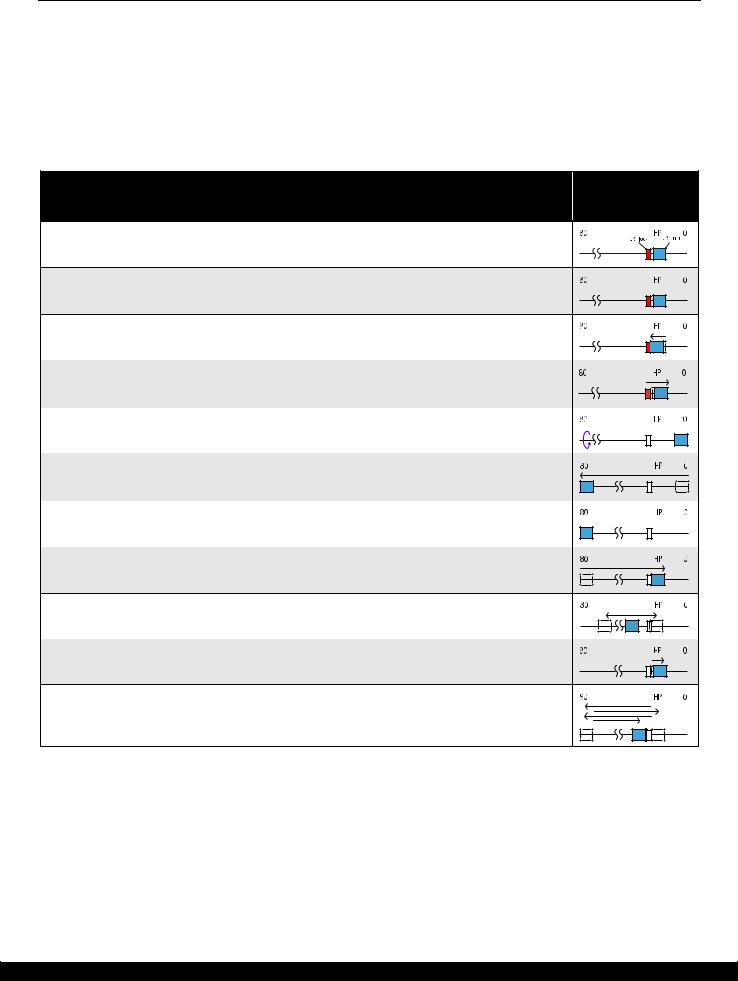
Table 1-1. Condition 1: Normal Power-on Sequence
CR Unit/PF Roller Operation*1 movement and
position*2
1. Printhead initialization and fuse inspection
1-1.Initializes the Printhead, and checks for the fuse on the circuit boards in the printer.*3
2.Checking for waste ink overflow
2-1.Checks the waste ink counter if the waste ink overflow is occurring.
3.Seeking the home position
3-1.The CR Unit moves to the 80-digit side slowly and confirms it touches the Change Lever (CR lock).
3-2.The CR Unit moves to the 0-digit side slowly.
3-3.After the PE Sensor checks if paper exists, the PF Motor rotates clockwise for one second and releases the CR lock.
3-4.While checking if the CR Unit does not touch the Change Lever (CR lock) or the foreign material, the CR Unit moves to the 80-digit side slowly until it touches the Left Frame.
3-5.The distance from the position where the CR Unit touched to the Left Frame is regarded as the standard distance from the origin position, and the home position is fixed.
From then on, the CR Unit position is monitored according to the signals from the CR Encoder.
3-6.The CR Unit moves to near its home position quickly.
4. Detecting ink cartridge and initializing ink system*4
4-1.To check the operation of the PIS Sensor and to detect ink, the CR Unit moves back and forth over the PIS Sensor two times.
4-2.The CR Unit returns to its home position.
5. Low temperature operation sequence*5
5-1.The CR Unit quickly moves back and forth between near the Change Lever and near the Left Frame for two times.
Note 1: The rotation directions of the PF Motor are as follows. Clockwise: Paper is fed normally Counterclockwise: Paper is fed backward
*2: The conditions of the CR lock are as follows.
Red |
CR lock is set |
White |
CR lock is released |
*3: The fatal error occurs if there is a problem such as the fuse blew. *4: The empty suction operation may occur depending on the situation.
*5: Executed when the detected temperature is under 5 oC (41oF) by the thermistor on the Printhead.
Troubleshooting |
Power-On Sequence |
12 |
Confidential
WF-2540 / WF-2530 / WF-2520 / WF-2510 / WF-2010 series |
Revision B |
Condition 2: Power-on sequence after recovering from a paper jam error (See Table 1-2.)
Turning on the printer after turning it off with a paper jam fatal error.
There still remains paper on the paper path out of the detecting area of the PE Sensor.
Maintenance error recovery has never been performed.
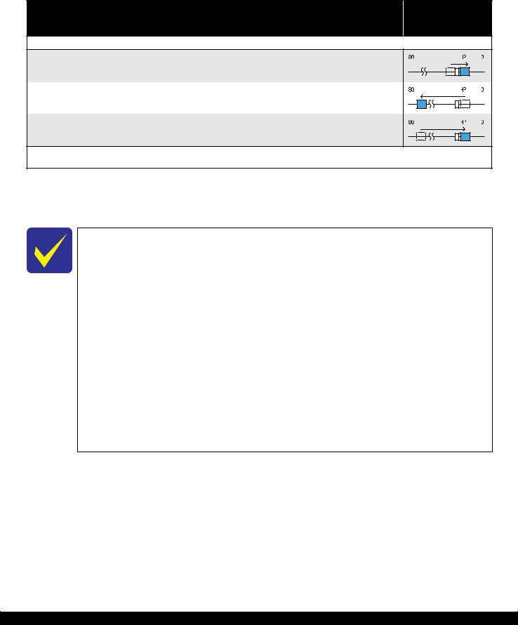
Table 1-2. Condition 2: Power-on Sequence after Recovering from a Paper Jam Error
CR Unit/PF Roller Operation movement and
position
Executes No.1 to No.3 on the normal power-on sequence (Table 1-1).
4. Detecting remaining paper
4-1.5.The CR Unit returns to its home position.
4-2.The CR Unit moves to the 80-digit side and confirms there is no paper.*1
4-3.The CR Unit quickly returns to its home position, and displays on the LCD or with flashing LEDs that the paper jam error occurs.
When the user removes the paper and releases the paper jam error by panel operation, the normal power-on sequence from No.1 (Table 1-1) is executed again.*2
Note *1: “Paper exists” is detected when the CR Unit touches the paper. When “paper does not exist” is detected, the power-on sequence of condition 1 (Table 1-1) is executed from No.4.
*2: If the paper jam error cannot be solved after repeating the power-on sequence on condition 2 (Table 1-2) twice, the printer turns into the paper jam fatal error for the third time.
To recover from the maintenance error, the dedicated software that can be downloaded from the web site which can be accessed from STM3 is required.
The printer operation related to the maintenance error recovery is as follows.
•When the waste ink counter reaches the threshold value (1) for the first time and the maintenance error occurs, the counter threshold of the maintenance error is changed to threshold value 2 after performing recovery from the maintenance error.
•After the threshold value (2) is enabled, the warning; to notify the possibility of ink leakage out of the printer, is displayed every time the waste ink counter increases by 1%.
•If the waste ink counter reaches the threshold value (2), the maintenance error occurs. Then, the waste ink counter is changed back to the threshold value (1) after recovering from the maintenance error, and the warning is displayed repeatedly according to the increment of the waste ink counter until the maintenance error occurs when the threshold value (2) is reached.
(Recovery from the maintenance error can be performed up to the specified number of times.)
Troubleshooting |
Power-On Sequence |
13 |
Confidential
WF-2540 / WF-2530 / WF-2520 / WF-2510 / WF-2010 series |
Revision B |
1.3 Fatal Error Code List
This section describes how to check the fatal error code, description, and the possible causes.
1.3.1 Displaying the Fatal Error Code
The fatal error code is stored in the EEPROM on the Main Board and can be read out using the Adjustment Program. The code can be displayed on the LCD of the control panel by a special panel operation.
Only the printer fatal error code can be displayed by this panel operation.
For the fatal error codes, descriptions, and their possible causes, see" 1.3.2 Printer Fatal Error Code (p15)".
The following describes the panel operation for the product to display the fatal error code.
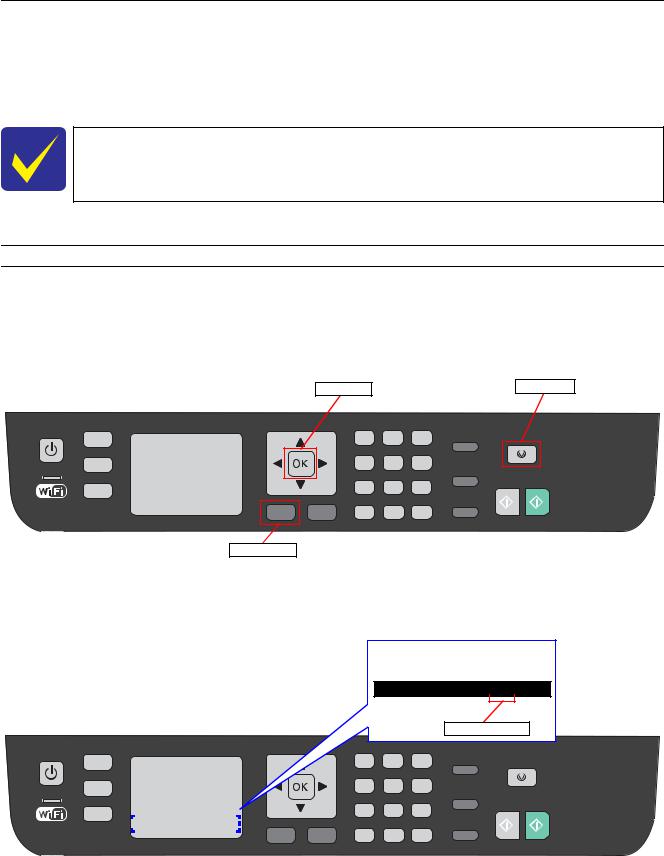
Method of displaying the fatal error code
1.Press the following buttons simultaneously while the fatal error is occurring.
Menu button
Stop button
OK button
OK button |
Stop button |
Menu button
Figure 1-2. Displaying the Fatal Error Code (1)
2. Check the displayed fatal error code.
LCD display
FATAL CODE:0x02
Fatal error code
|
|
|
|
|
|
|
|
|
|
|
|
|
|
|
|
|
|
|
|
|
|
|
|
|
|
|
|
|
|
|
|
|
|
|
|
|
|
|
|
|
|
|
|
|
|
|
|
|
|
|
|
|
|
|
|
|
|
|
|
|
|
|
|
|
|
|
|
|
|
|
|
|
|
|
|
|
|
|
|
|
|
|
|
|
Figure 1-3. Displaying the Fatal Error Code (2) |
|
|||||||||
|
|
|
|
|
|
|
|
|
|
|
|
|
|
|
|
|
|
|
|
|
|
|
|
Troubleshooting |
|
|
|
|
|
|
|
|
|
|
|
|
|
|
|
|
|
Fatal Error Code List |
14 |
||||
Confidential

WF-2540 / WF-2530 / WF-2520 / WF-2510 / WF-2010 series |
Revision B |
1.3.2 Printer Fatal Error Code
This section describes the printer fatal error code and the possible cause for this product.
Table 1-3. Fatal Error List (Printer)
Error type |
Error |
Error name |
Possible cause |
|
code |
||||
|
|
|
||
|
|
|
|
DC motor error
|
|
• |
CR Motor failure |
|
|
|
• CR Unit drive mechanism overload (paper jam, foreign object, |
||
|
|
|
insufficient grease, deformation of the Main Frame) |
|
01H |
CR PID excess load error |
• Some part may be detached. (Paper Guide Upper Assy, Cap Assy) |
||
• Tooth skip of the CR Timing Belt |
||||
|
|
|||
|
|
• Improper tension of the CR Timing Belt |
||
|
|
• |
Cable disconnection |
|
|
|
• Main Board failure (Motor driver failure) |
||
|
|
|
||
|
|
• CR Encoder failure (contaminated/detached scale, Encoder Sensor |
||
02H |
CR PID excess speed error |
|
failure) |
|
|
|
• Main Board failure (Motor driver failure) |
||
|
|
|
||
|
|
• CR Encoder failure (contaminated/detached scale, Encoder Sensor |
||
|
|
|
failure) |
|
|
|
• Some external force is applied to the printer such as stopping the CR Unit |
||
03H |
CR PID reverse error |
|
during printer operation, vibration or the like. |
|
|
|
• Tooth skip of the CR Timing Belt |
||
|
|
• |
Paper jam |
|
|
|
• Main Board failure (Motor driver failure) |
||
|
|
|
||
|
|
• CR Encoder failure (contaminated/detached scale, Encoder Sensor |
||
|
|
|
failure) |
|
|
|
• |
CR Motor failure |
|
04H |
CR PID lock error |
• CR Unit drive mechanism overload (paper jam, foreign object, |
||
|
insufficient grease, deformation of the Main Frame) |
|||
|
|
|
||
|
|
• Some part may be detached. (Paper Guide Upper Assy, Cap Assy) |
||
|
|
• |
Cable disconnection |
|
|
|
• Main Board failure (Motor driver failure) |
||
|
|
|
||
|
|
• CR Encoder failure (contaminated/detached scale, Encoder Sensor |
||
08H |
CR load position reverse error |
|
failure) |
|
|
|
• Main Board failure (Motor driver failure) |
||
|
|
|
||
|
|
• CR Encoder failure (contaminated/detached scale, Encoder Sensor |
||
|
|
|
failure) |
|
09H |
CR load position excess speed error |
• Tooth skip of the CR Timing Belt |
||
• Improper tension of the CR Timing Belt |
||||
|
|
|||
|
|
• |
Paper jam |
|
|
|
• Main Board failure (Motor driver failure) |
||
|
|
|
|
|
|
|
• |
CR Motor failure |
|
|
|
• CR Unit drive mechanism overload (paper jam, foreign object, Change |
||
0AH |
CR load position excess load error |
|
Lever failure) |
|
|
|
• |
Cable disconnection |
|
|
|
• Main Board failure (Motor driver failure) |
||
|
|
|
|
|
|
|
• |
PF Motor failure |
|
|
|
• PF drive mechanism overload (paper jam, foreign object, insufficient |
||
|
|
|
grease, deformation of the Main Frame) |
|
F1H |
PF PID excess load error |
• |
Tooth skip of the PF Timing Belt |
|
|
|
• Improper tension of the PF Timing Belt |
||
|
|
• |
Cable disconnection |
|
|
|
• Main Board failure (Motor driver failure) |
||
|
|
|
||
|
|
• PF Encoder failure (contaminated/detached scale, Encoder Sensor failure) |
||
F2H |
PF PID excess speed error |
• Tooth skip of the PF Timing Belt |
||
• Improper tension of the PF Timing Belt |
||||
|
|
|||
|
|
• Main Board failure (Motor driver failure) |
||
Troubleshooting |
Fatal Error Code List |
15 |
Confidential

WF-2540 / WF-2530 / WF-2520 / WF-2510 / WF-2010 series |
|
Revision B |
||||
|
|
|
Table 1-3. Fatal Error List (Printer) |
|||
|
|
|
|
|
|
|
|
Error type |
Error |
Error name |
|
Possible cause |
|
|
code |
|
|
|||
|
|
|
|
|
|
|
|
|
|
|
|
|
|
|
|
|
|
• PF Encoder failure (contaminated/detached scale, Encoder Sensor failure) |
|
|
|
|
|
|
• Tooth skip of the PF Timing Belt |
|
|
|
|
F3H |
PF PID reverse error |
• Improper tension of the PF Timing Belt |
|
|
|
|
• |
Paper jam |
|
||
|
|
|
|
|
||
|
|
|
|
• Paper is pulled out from the ASF side when paper is fed |
|
|
|
|
|
|
• Main Board failure (Motor driver failure) |
|
|
|
|
|
|
|
|
|
|
|
|
|
• PF Encoder failure (contaminated/detached scale, Encoder Sensor failure) |
|
|
|
|
|
|
• |
PF Motor failure |
|
|
|
F4H |
PF PID lock error |
• PF drive mechanism overload (paper jam, foreign object, insufficient |
|
|
|
|
|
grease, deformation of the Main Frame) |
|
||
|
|
|
|
|
|
|
|
|
|
|
• |
Cable disconnection |
|
|
DC motor |
|
|
• Main Board failure (Motor driver failure) |
|
|
|
|
|
|
|
|
|
|
|
|
• |
PF Encoder failure (contaminated/detached scale, Encoder Sensor failure) |
|
|
|
error |
|
|
|
||
|
|
F8H |
PF load position reverse error |
• |
Tooth skip of the PF Timing Belt |
|
|
|
|
|
• Improper tension of the PF Timing Belt |
|
|
|
|
|
|
|
|
|
|
|
|
|
• PF Encoder failure (contaminated/detached scale, Encoder Sensor failure) |
|
|
|
|
F9H |
PF load position excess speed error |
• Tooth skip of the PF Timing Belt |
|
|
|
|
• Improper tension of the PF Timing Belt |
|
|||
|
|
|
|
|
||
|
|
|
|
• Main Board failure (Motor driver failure) |
|
|
|
|
|
|
|
|
|
|
|
|
|
• |
PF Motor failure |
|
|
|
|
|
• PF drive mechanism overload (paper jam, foreign object) |
|
|
|
|
FAH |
PF load position excess load error |
• |
Tooth skip of the PF Timing Belt |
|
|
|
|
|
• Improper tension of the PF Timing Belt |
|
|
|
|
|
|
• |
Cable disconnection |
|
|
|
|
|
|
|
|
|
|
D1H |
CR (PID) driving time error |
• |
Main Board failure (Firmware failure) |
|
|
|
|
|
|
|
|
|
|
|
|
• |
Change Lever failure |
|
|
|
D2H |
CR (load position) driving time error |
• |
CR Motor failure |
|
|
Motor drive |
|
|
• Main Board failure (Motor driver failure) |
|
|
|
|
|
|
|
|
|
|
time error |
D3H |
PF (PID) driving time error |
• |
Main Board failure (Firmware failure) |
|
|
|
|
||||
|
|
|
|
|
|
|
|
|
|
|
• |
Change Lever failure |
|
|
|
D4H |
PF (BS) driving time error |
• |
CR Motor failure |
|
|
|
|
|
• Main Board failure (Motor driver failure) |
|
|
|
|
|
|
|
|
|
|
|
40H |
Transistor temperature error |
• |
Main Board failure |
|
|
|
|
|
|
|
|
|
Printhead |
41H |
X-Hot detect error (pre printing) |
• |
Printhead failure |
|
|
|
|
|
|||
|
system error |
42H |
X-Hot detect error (after flushing) |
|
||
|
• |
Main Board failure |
|
|||
|
|
|
||||
|
|
|
|
|
||
|
|
43H |
Head temperature error |
|
||
|
|
|
|
|
||
|
|
|
|
|
|
|
|
|
|
|
• |
Foreign object |
|
|
|
50H |
Home position error |
• Deformation of the Main Frame |
|
|
|
|
• |
Change Lever failure |
|
||
|
Sequence |
|
|
|
||
|
|
|
• |
Paper jam |
|
|
|
error |
|
|
|
||
|
|
|
|
|
|
|
|
|
Contact error at ink replacement timing |
• |
Foreign object |
|
|
|
|
|
|
|||
|
|
56H |
• |
Ink Cartridges are not installed correctly |
|
|
|
|
(Power-off) |
|
|||
|
|
|
• |
Paper jam |
|
|
|
|
|
|
|
||
|
|
|
|
|
|
|
|
|
|
|
• |
Foreign object |
|
|
Sequence |
5BH |
Insoluble paper jam error |
• |
Deformation of the Main Frame |
|
|
error |
• |
Change Lever failure |
|
||
|
|
|
|
|||
|
|
|
|
• |
Paper jam |
|
|
|
|
|
|
|
|
|
|
|
|
• |
Ink Cartridge failure |
|
|
Ink device |
B0H - |
Ink device error |
• |
Holder Board Assy failure (CSIC Terminal failure/CR Contact Module |
|
|
error |
CFH |
|
failure) |
|
|
|
|
|
|
|||
|
|
|
|
• |
Main Board failure |
|
|
|
|
|
|
|
|
|
Circuit error |
80H |
Circuit error (include blowout of a fuse) |
• |
Main Board failure |
|
|
|
|
|
|
|
|
Troubleshooting |
Fatal Error Code List |
16 |
Confidential
WF-2540 / WF-2530 / WF-2520 / WF-2510 / WF-2010 series |
Revision B |
||||
|
|
|
Table 1-3. Fatal Error List (Printer) |
||
|
|
|
|
|
|
|
Error type |
Error |
Error name |
Possible cause |
|
|
code |
|
|||
|
|
|
|
|
|
|
|
|
|
|
|
|
|
|
|
• Defective Fault Detection Plate* (detachment, peeled reflector) |
|
|
|
83H |
Reflector no reflection error |
• Sensor failure (contaminated Sensor, damaged FFC, PIS Board |
|
|
|
|
|
installation failure) |
|
|
|
|
|
|
|
|
|
|
|
• Abnormal sensor output (Sensor failure, PIS Board failure) |
|
|
|
88H |
Excessive Light error |
• Unexpected excessive amount of light such as too much diffused light |
|
|
|
from outside is shed on the sensor because the housings are removed. |
|
||
|
|
|
|
|
|
|
PIS Board |
|
|
(When used outdoors or near the window where direct sunlight comes in) |
|
|
device error |
|
|
|
|
|
|
|
• Sensor failure (PIS Board installation failure, contaminated Sensor) |
|
|
|
|
|
|
|
|
|
|
|
|
• Abnormal sensor output (Break of FFC during printer operation, PIS |
|
|
|
|
|
Board failure) |
|
|
|
89H |
Insufficient Light error |
• Unable to accurately detect where the fault detection plate is because too |
|
|
|
|
|
much diffused light from outside is shed on the sensor. (When used |
|
|
|
|
|
outdoors or near the window where direct sunlight comes in) |
|
|
|
|
|
• Ink Cartridge failure (contaminated/damaged prism) |
|
|
|
|
|
|
|
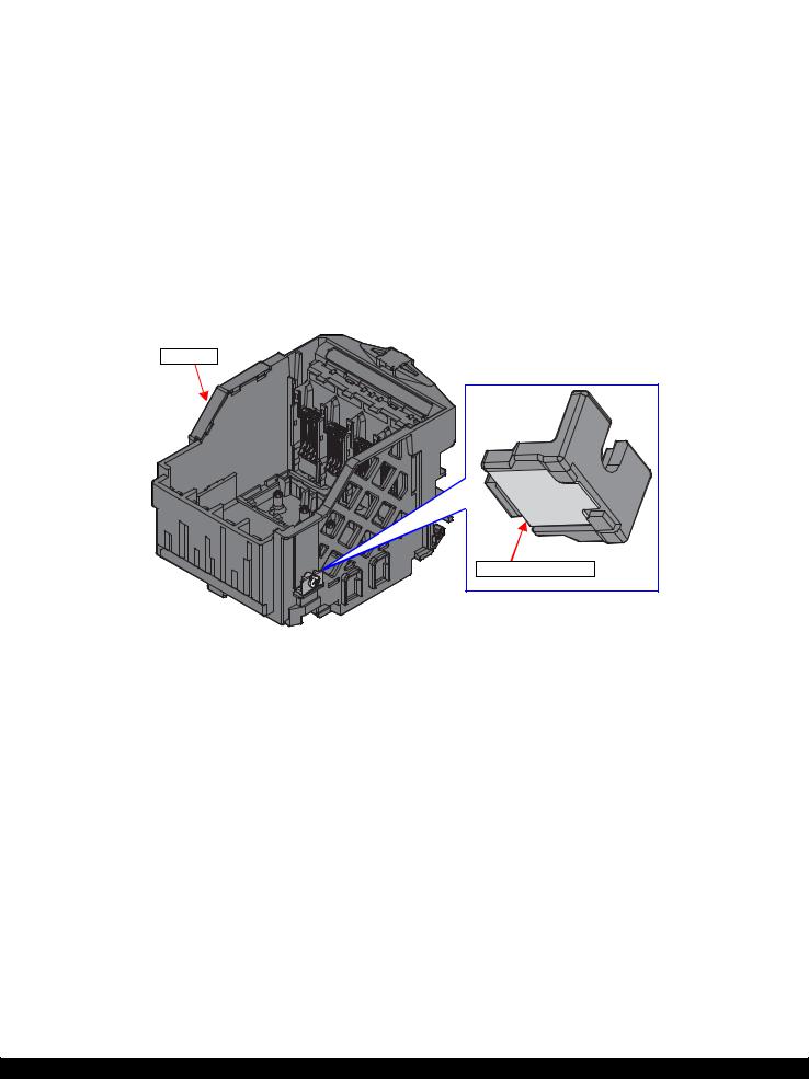
Note *: Fault Detection Plate is a reflector attached on the CR Unit. (See Fig. 1-4)
CR Unit
Fault Detection Plate |
Figure 1-4. Fault Detection Plate
Troubleshooting |
Fatal Error Code List |
17 |
Confidential
WF-2540 / WF-2530 / WF-2520 / WF-2510 / WF-2010 series |
Revision B |
1.3.3 Scanner Fatal Error Code
This section describes the scanner fatal error code and the possible cause for this product.
Table 1-4. Fatal Error List (Scanner)
Error code |
Error name |
|
Possible cause |
|
|
|
|
|
|
|
|
• |
CIS Module failure |
|
|
|
• Scanner Housing Upper failure (home seek pattern*1 is dirty) |
||
|
|
• Scanner Housing Lower failure (the rack section*2 is damaged) |
||
10H |
Home position detection error |
• |
Scanner Motor failure |
|
• |
Insufficient grease |
|||
|
|
|||
|
|
• |
Foreign object |
|
|
|
• |
FFC disconnection/failure |
|
|
|
• |
Main Board failure |
|
|
|
|
|
|
|
|
• |
Scanner Motor failure |
|
|
|
• |
Insufficient grease |
|
14H |
Measurement error |
• |
Foreign object |
|
|
|
• |
Gear failure |
|
|
|
• Deformation of the shaft |
||
|
|
|
|
|
|
|
• |
CIS Module failure |
|
20H |
LED lightning error |
• |
Foreign object |
|
• Scanner Housing Upper failure (white standard pattern*1 is dirty) |
||||
|
|
|||
|
|
• |
Main Board failure |
|
|
|
|
|
|
|
|
• |
Paper jam |
|
36H |
Paper jam error |
• |
Loading/ejecting papers out of the standard range or curled papers |
|
|
|
• Using long papers (Legal or longer) |
||
|
|
|
|
|
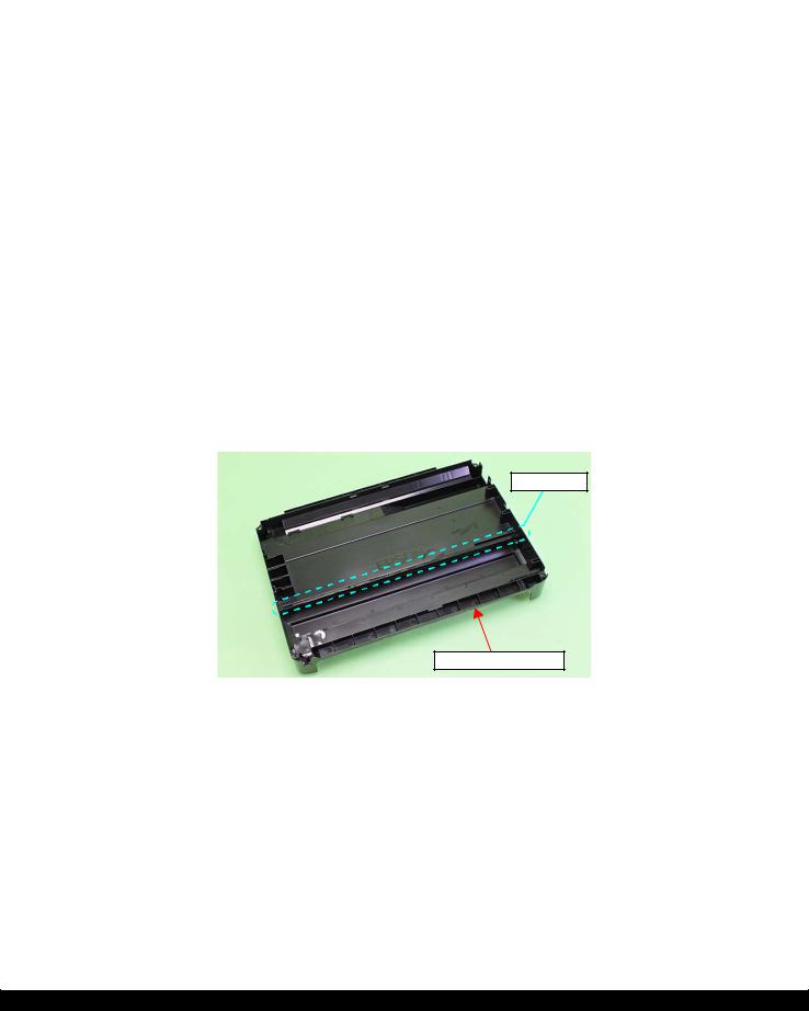
Note *1: The home seek pattern and the white standard pattern are attached on the back of the Scanner Housing Upper near the home position.
*2: The rack section is the linearly-arranged toothed area on the Scanner Housing Lower. (See Fig. 1-5.)
Rack section
Scanner Housing Lower
Figure 1-5. Rack section
Troubleshooting |
Fatal Error Code List |
18 |
Confidential

CHAPTER 2
DISASSEMBLY/REASSEMBLY
Confidential
WF-2540 / WF-2530 / WF-2520 / WF-2510 / WF-2010 series |
Revision B |
2.1 Overview
In this chapter, the product names are called as follows:
WF-2540 Series: WF-2540/WF-2548/WF-2541
WF-2530 Series: WF-2530/WF-2532/WF-2538/WF-2531
WF-2520 Series: WF-2520/WF-2528/WF-2521
WF-2510 Series: WF-2510/WF-2511/WF-2512
WF-2010 Series: WF-2010
This chapter describes procedures for disassembling the main parts/units of this product. Unless otherwise specified, disassembled parts/units can be reassembled by reversing the disassembly procedure. See the cautions or tips for disassembly/reassembly described in "2.3 Detailed Disassembly/Reassembly Procedure for each Part/ Unit (p40)".
Read the "Safety Precautions(p3)" before disassembling and reassembling.
When you have to remove units or parts that are not described in this chapter, see the exploded diagrams of SPI (Service Parts Information).
2.1.1 Tools
Use only specified tools to avoid damaging the printer.
Name |
Availability |
EPSON Part Code |
|
|
|
(+) Phillips screwdriver #1 |
O |
1080530 |
|
|
|
(+) Phillips screwdriver #2 |
O |
--- |
|
|
|
Flathead screwdriver |
O |
--- |
|
|
|
Flathead Precision screwdriver #1 |
O |
--- |
|
|
|
Tweezers |
O |
--- |
|
|
|
Longnose pliers |
O |
--- |
|
|
|
Acetate tape |
--- |
1003963 |
|
|
|
Note 1: Some of the tools listed above are commercially available.
2:EPSON provides the tools listed with EPSON part code.
2.1.2Jigs
Name |
Quantity |
EPSON Part Code |
Spring hook jig* |
1 |
Can be made with a commercial item See " Making the Spring Hook Jig (p20)". |
|
|
|
Thickness gauge (1.5 mm) |
2 |
Commercially available |
|
|
|
Thickness gauge (2.0 mm) |
2 |
Commercially available |
|
|
|
Sonic tension meter |
1 |
1294120 |
|
|
|
Note *: If performing the disassembling/reassembling procedure is difficult using tweezers such as when reassembling " Cap Lever / Cap Assy (p47)", the spring hook jig helps you to remove/attach the spring easier.
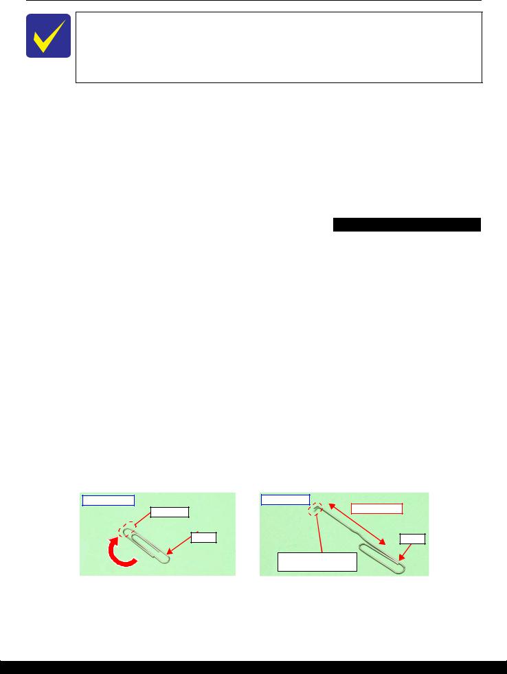
2.1.2.1 Making the Spring Hook Jig
Fold a clip (commercial item) as shown in Fig. 2-1.
Before folding
Fold here |
After folding
40 mm or more
Clip |
Clip |
Fold appropriate length to hitch a spring.
Figure 2-1. Making the Spring Hook Jig
Disassembly/Reassembly |
Overview |
20 |
Confidential

WF-2540 / WF-2530 / WF-2520 / WF-2510 / WF-2010 series |
Revision B |
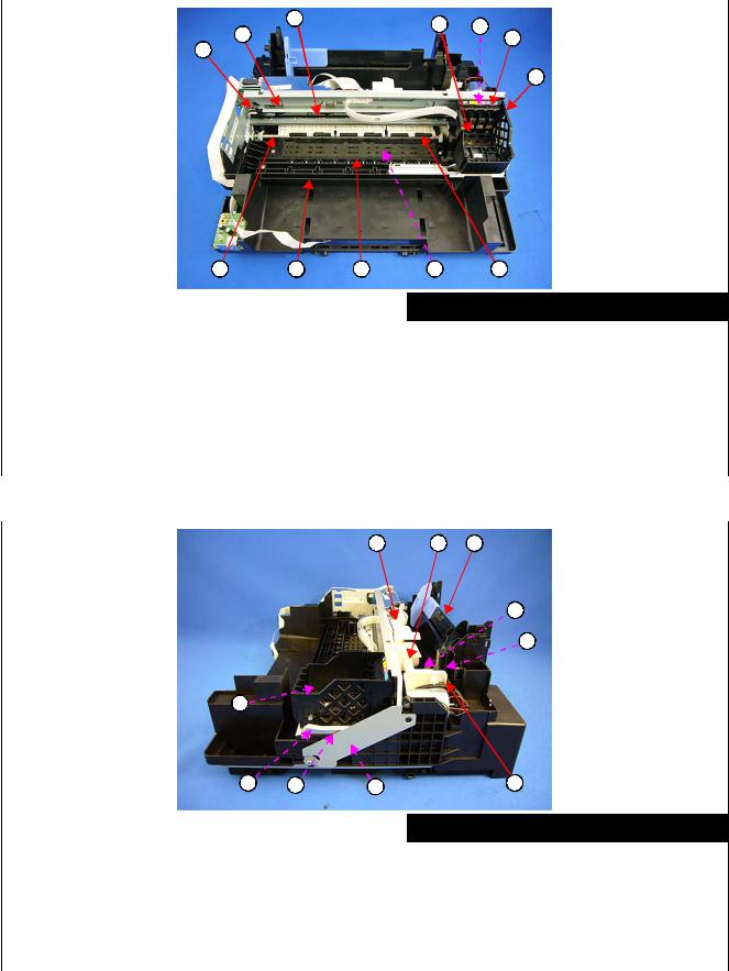
2.1.3 Locations of the Parts/Units
This section shows the locations of the main parts/units of this product.
The parts/units which can not be seen in the following pictures are indicated in dotted lines ( 

 ).
).
Exterior parts
Front |
1 |
Right |
|
5
2 |
3 |
4 |
6 |
Left |
8 |
Rear |
10 |
|
|
|
|
7 |
|
|
9 |
|
|
|
|
|
No. |
|
Name |
No. |
Name |
|
|
|
|
|
1Housing Rear (p30)
2Tray Front Assy (p30)
3Frame Base Assy (p35) Panel Unit (p32)
4Panel Board (p37) / Panel Button (p37) / LCD Unit (p37) / Panel Housing Upper Assy (p37)
5Hinge (p30) (Scanner function compatible model)
6Housing Right (p30) Housing Left Assy (p30)
•Housing Left (p37)
7• Ethernet Cover (p37) (Ethernet function noncompatible model)
|
ADF/Scanner Unit (p30) |
|
|
• ADF Unit (p36) (ADF function compatible model) |
|
|
ADF Paper Guide Cover Assy (p31) / Paper Support |
|
|
Cover (p31) / Bevel Gear Shaft (p36) / Combination |
|
|
Gear 24.9.6 (p36) / ADF Document Support (p36) / |
|
8 |
ADF Pad Assy (p36) |
|
• Scanner Unit (p36) (Scanner function compatible |
||
|
||
|
model) |
|
|
Scanner Housing Upper (p36) / Scanner Carriage Unit |
|
|
(p36) / Scanner Housing Lower (p36) / CIS Module |
|
|
Unit (p36) / Scanner Motor (p36) |
|
|
|
|
9 |
Paper Support (p30) |
|
|
|
|
10 |
Paper Support Sub (p30) |
Figure 2-2. Exterior Parts
Disassembly/Reassembly |
Overview |
21 |
Confidential
WF-2540 / WF-2530 / WF-2520 / WF-2510 / WF-2010 series |
|
Revision B |
||
|
Printer mechanism |
|
|
|
|
|
|
|
|
3 |
4 |
5 |
|
|
2 |
|
|||
|
6 |
|
||
1 |
|
|
|
|
|
|
|
7 |
|
|
8 |
9 |
10 |
11 |
12 |
|
|
|
|
|
|
|
|
No. |
Name |
|
|
No. |
|
Name |
|
|
|
|
|
|
|
1 |
CR Driven Pulley Assy (p35) |
|
|
7 |
CR Unit (p38) |
|
|
|
|
|
|
|
|
2 |
CR Scale (p35) |
|
|
8 |
PF Roller Unit (p38) |
|
|
|
|
|
|
|
|
3 |
CR Timing Belt (p38) |
|
|
9 |
Star Wheel Holder Assy (p31) |
|
|
|
|
|
|
|
|
4 |
Printhead (p30) |
|
|
10 |
Paper Guide Front Unit (p30) |
|
|
|
|
|
|
|
|
5 |
CR Encoder Sensor (p38) |
|
|
11 |
Paper Guide Lower Porous Pad (p30) |
|
|
|
|
|
|
|
|
6 |
Holder Board Assy (p30) |
|
|
12 |
Paper Guide Upper Assy (p38) |
|
|
|
|
|
|
||
|
|
Figure 2-3. Printer |
Mechanism: Front |
|||
|
|
|
|
|
|
|
|
|
|
1 |
2 |
3 |
|
|
|
|
|
|
|
4 |
|
|
|
|
|
|
5 |
|
|
6 |
|
|
|
|
|
|
7 |
8 |
9 |
10 |
|
|
|
|
|
|
|
|
|
|
|
No. |
Name |
|
|
No. |
Name |
|
|
|
|
|
|
|
|
|
1 |
LD Roller Cover (p35) |
|
|
6 |
PIS Board Assy (p30) |
||
|
|
|
|
|
|
|
|
2 |
LD Roller Assy (p34) |
|
|
7 |
Cap Lever (p31) |
||
|
|
|
|
|
|
|
|
3 |
Hopper (p39) |
|
|
8 |
Cap Assy (p31) |
||
|
|
|
|
|
|
|
|
4 |
Retard Roller Assy (p30) |
|
|
9 |
Porous Pad for Cap Assy (p33) |
||
|
|
|
|
|
|
|
|
5 |
Paper Back Lever (p30) |
|
|
10 |
Pump Unit (p38) |
||
|
|
|
|
|
|
||
|
|
Figure 2-4. Printer |
Mechanism: Right |
||||
|
|
|
|
|
|
|
|
Disassembly/Reassembly |
|
Overview |
22 |
||||
Confidential
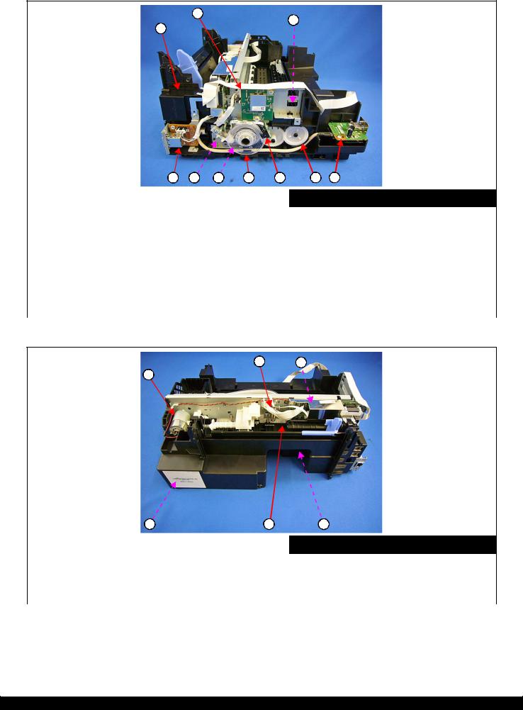
WF-2540 / WF-2530 / WF-2520 / WF-2510 / WF-2010 series |
Revision B |
2
3
1
|
4 |
5 |
6 |
7 |
8 |
9 |
10 |
|
|
|
|
|
|
|
|
No. |
Name |
|
|
|
No. |
|
Name |
|
|
|
|
|
|||
1 |
FAX Assy (p31) (FAX function compatible model) |
|
5 |
PF Motor Assy (p38) |
|||
|
|
|
|
|
|||
2 |
Wireless LAN Module (p34) (Wireless LAN function |
|
6 |
PF Timingbelt (p34) |
|||
compatible model) |
|
|
|
|
|
||
|
|
|
|
|
|
|
|
|
|
|
|
|
|
|
|
3 |
EJ Roller (p31) |
|
|
|
7 |
PF Scale (p34) |
|
|
|
|
|
|
|
|
|
|
Ethernet Board Assy (p31) |
|
|
|
8 |
PF Encoder Sensor (p34) |
|
|
|
|
|
|
|
|
|
4 |
|
|
|
9 |
EJ Roller Gear (p34) |
||
(Ethernet function compatible function) |
|
|
|||||
|
|
|
|
|
|
||
|
|
|
|
|
10 |
USB Board (p31) (USB function compatible model) |
|
|
|
|
|
|
|
|
|
Figure 2-5. Printer Mechanism: Left
2 3
1
|
4 |
5 |
6 |
|
|
|
|
|
|
No. |
Name |
|
No. |
Name |
|
|
|
|
|
1 |
CR Motor (p34) |
|
4 |
Waste Ink Pad Assy (p30) |
|
|
|
|
|
2 |
Head FFC (p38) |
|
5 |
PE Sensor Lever (p34) |
|
|
|
|
|
3 |
Main Board (p34) |
|
6 |
PS Unit (p34) |
|
|
|
|
|
|
|
Figure 2-6. Printer |
Mechanism: Rear |
|
Disassembly/Reassembly |
Overview |
23 |
Confidential

WF-2540 / WF-2530 / WF-2520 / WF-2510 / WF-2010 series |
Revision B |
2.1.4 Standard Operation Time for Servicing the Product
The following are the standard operation time for servicing the product. This standard operation time was determined with the MTTR result measured using the prototype of WF-2540 series which have the most functions. For other models described in this manual, perform the repair work referring to this standard operation time though the time varies due to the structural difference between models.
The underlined parts/units are supplied as After Service Parts.
Table 2-1. Standard Operation Time
|
|
Time (mm:ss) |
|
Parts/Unit |
|
Adjustment/ |
|
Replacement |
|
||
|
|
||
|
inspection |
|
|
|
|
|
|
|
|
|
|
Housing Rear |
0:36 |
1:31 |
2:07 |
|
|
|
|
Paper Support |
0:09 |
|
|
|
|
|
|
Paper Support Sub |
0:23 |
|
|
|
|
|
|
Tray Front Assy |
0:15 |
|
|
|
|
|
|
Tray Front |
0:15 |
|
|
|
|
|
|
Tray Front Support |
0:22 |
|
|
|
|
|
|
Paper Guide Front Unit |
0:49 |
7:44 |
8:33 |
|
|
|
|
Paper Guide Lower Porous Pad |
0:54 |
0:45 |
1:39 |
|
|
|
|
PIS Shield Plate A |
0:33 |
|
|
|
|
|
|
PIS Board Assy |
1:11 |
|
|
|
|
|
|
Waste Ink Pad Assy |
0:42 |
0:45 |
1:27 |
|
|
|
|
Paper Back Lever |
1:52 |
|
|
|
|
|
|
Retard Roller Assy |
2:00 |
0:47 |
2:47 |
|
|
|
|
FFC Cover Outer |
0:26 |
|
|
|
|
|
|
Holder Board Assy |
0:56 |
|
|
|
|
|
|
CR Contact Module |
1:35 |
|
|
|
|
|
|
CSIC Connector |
1:46 |
|
|
|
|
|
|
Holder Board |
1:46 |
|
|
|
|
|
|
Printhead |
2:20 |
17:39 |
19:59 |
|
|
|
|
Reflector PIS Assy |
0:37 |
|
|
|
|
|
|
ADF Paper Guide Cover Assy |
0:25 |
|
|
|
|
|
|
ADF Cable Cover |
0:27 |
|
|
|
|
|
|
Paper Support Cover |
0:06 |
|
|
|
|
|
|
Document Mat |
0:13 |
|
|
|
|
|
|
ADF/Scanner Unit |
2:46 |
2:52 |
5:38 |
|
|
|
|
ADF Unit |
3:32 |
2:52 |
6:24 |
|
|
|
|
ADF Hinge Left |
5:28 |
|
|
|
|
|
|
ADF Document Support |
7:06 |
|
|
|
|
|
|
ADF Hinge Right |
3:53 |
|
|
|
|
|
|
Cover Gear Assy |
4:29 |
|
|
|
|
|
|
Bevel Gear Shaft |
4:34 |
|
|
|
|
|
|
Combination Gear 24.9.6 |
4:33 |
|
|
|
|
|
|
ADF Frame Assy |
5:04 |
|
|
|
|
|
|
ADF Front Frame |
6:00 |
|
|
|
|
|
|
Spur Gear 20.4 / 25.8 |
6:04 |
|
|
|
|
|
|
Disassembly/Reassembly Overview 24
Confidential
Loading...