


XK3190-A1+P
Weighing Indicator
USER’ S GUIDE
Attention:
Please read this User’s Guide carefully when you use the indicator!
X K 3 1 9 0 - A 1+P
1 . Specifications
2 . Installation
2.1Front & Back View of Indicator
2.2Keyboard Function
2.3Connecting Loadcell to Indicator
3.Calibration
4.Operating Instructions
4.1Starting and Starting auto zero setting at turning on
4.2Manual Zero Setting (Semi-automatically setting zero )
4.3Tare Function
4.4Connecting Scoreboard to Indicator
4.5Connecting Pinter to Indicator
4.6Connecting Serial Communication port to Indicator
4.7Setting of Time and Date
4.8 Storing, Checking and Deleting of Data
4.9insufficient voltage indication
5.Maintenance and Announcements
6.Errors and Information
Important Notes!!!
1 Printer interface invalid due to the built-in micro-printer (optional supply upon special requirement)
2 The function key is used as the paper roll key, it works upon pressing and stops working upon releasing.
3 “5” should be chosen as printer parameter TypE
4 There is only one print format - linked bill format when micro-printer used. 5 The discount ratio printer option must be off while using:
“odE=0”
“dct=0”
X K 3 1 9 0 - A 1+P
1 Specification
1 |
Model |
XK3190-A1+ |
2 |
Sample rated |
5~25 times / sec |
|
|
|
3 |
Load cell sensitivity |
1~ 2mv/v |
4 |
Division |
1/2/5/10/20/50/100 optional |
5 |
Display |
7-bits LED digital display 0.56” in character |
|
|
height and 7 status indicating. |
6 |
Clock |
can display day/month/year and |
|
|
second/minute/hour |
7 |
Scoreboard display interface |
Using serial output method : |
|
|
current loop signal, transmission distance ≤50m |
|
|
RS323 signal, transmission distance ≤30m |
8 |
Communication port |
RS-232C |
|
|
Baud rate: 600/1200/2400/4800/9600 optional |
9 |
Printing Port |
Standard parallel output port, can connect with |
|
|
Tpup16 micro-printer, TM800,LX-300, KXP |
|
|
1121and LQ-1600k wide-line printer. |
10 |
Power Supply |
AC 187 242V ; 49~50Hz |
|
|
The built-in repair-proof storage cell; 12V,7AH |
11 |
Operating Temperature and |
0 40 , ≤ 90% RH |
|
Relative Humidity |
|
12 |
Storage /transportation |
20 50 |
|
Temperature |
|
13 |
Fuse |
500mA |
X K 3 1 9 0 - A 1+P
2.Installation
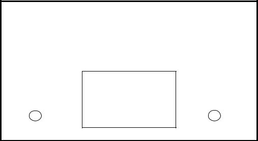
2.1Front & Back View of the Indicator
|
UNIT:KG |
|
|
|
|
|
|
|
|
|
|
|
1 |
2 |
3 |
|
|
|
|
|
|
|
|
|
|
|
|||
|
|
|
|
ACCU |
PRE-T |
FUN |
TARE |
ENTER |
|
|
|
|
|
|
|||||
|
|
|
|
|
|
|
|
|
|
|
|
|
|
4 |
5 |
6 |
0 |
|
|
MONEY PRICE AUTO DATE |
TIME TARE STABLE |
|
|
||||||
CLEAR |
CHECK |
DATE |
STORE |
WEIGH |
|
||||
|
|
|
|
|
|
|
|
|
|
|
|
|
|
7 |
8 |
9 |
|
|
|
|
|
|
|
SET |
CALB |
TIME |
ZERO |
|
|
|
|
|
|
|
|
|
|
|
|
|
|
|
|
|
|
|
|||
|
(Graph 2-1) Front View of Indicator |
|
|
|
|
||||
|
* ACCU - accumulating |
FUNfunction |
CALB – Calibrating |
|
|
|
|||
( 25 ) pins |
|
(15 ) pins |
|
( 9) pins |
|
|
|
|
|
|
|
Print output port |
RS-232C; Scoreboard output port |
Loadcell input port |
|||
Nameplate
Power source |
Fuse |
(Graph 2-2) Back View of the Indicator
X K 3 1 9 0 - A 1+P
2.2 Keyboard Function
|
Key |
Function |
1 |
[ACCU],[ UNIT |
No meaning |
|
PRICE] |
|
2 |
|
In calibration mode, pressing [PRE-TARE/2] , can input |
|
|
digital key “2”; In weighing mode, the key is used for |
|
|
presetting tare. |
3 |
[DELETE/4] |
In calibration mode, pressing [DELETE/4], can input digital |
|
|
key “4”; In weighing mode, it is deleting function key , more |
|
|
details shown in episode “deleting”. |
4 |
[CHECK/5] |
In calibration mode, pressing [CHECK/5], can input digital |
|
|
key “5”; In weighing mode, it is checking function key , |
|
|
more details shown in episode “checking”. |
5 |
[DATE/6] |
In calibration mode, pressing [DATE/6] can input digital |
|
|
key “6” ;In weighing mode, it is date function key , more |
|
|
details shown in episode “setting of time and date”. |
6 |
[SET PRINT] |
In calibration mode, pressing [SET PRINT] can input digital |
|
|
key “7” ;In weighing mode, it is printing setup key , more |
|
|
details shown in episode “printing function”. |
7 |
[CALB/8] |
In calibration mode, it is calibration function key ; In other |
|
|
operation modes it only inputs digital key “8” |
8 |
[TIME/9] |
In calibration mode, pressing [TIME/9] can input digital key |
|
|
“9” ;In weighing mode, it is time function key , more details |
|
|
shown in episode “setting of time and date”. |
9 |
[STORE/0] |
In calibration mode, pressing [STORE/0] can input digital |
|
|
key “0” ;In weighing mode, it is storing function key , more |
|
|
details shown in episode “storing data”. |
10 |
[ACCU/1],[ UNIT |
In calibration mode, pressing [ACCU/1] or [ UNIT |
|
PRICE/3] |
PRICE/3] can input digital key, “1”; “3”;In weighing mode, |
|
|
there are no meaning. |
11 |
In weighing mode, when stable sign appears, press [TARE] key to clear tare. If |
|
|
indicator displays zero, the weight value is net weight. |
|
12 |
In weighing mode, when stable sign appeares, press [ZERO] key to clear limited |
|
|
weight on the platform. You can set zero range , generally the zero range is 4% of full |
|
|
scale. |
|
13 |
In weighing mode, when stable sign appears, press [PRINT] key to print weight data. |
|
14 |
In calibration mode, press [ENTER] key to confirm that parameters have been inputted |
|
|
and will enter to next parameter setting automatically. When indicator is in date, time, |
|
|
printing and communication setting mode, push [ENTER] key to confirm that |
|
|
parameters have been inputted. |
|

X K 3 1 9 0 - A 1+P
15In calibration or parameters setting mode, pressing [weigh], it will exit from original calibration or setting mode and return to weighing mode.
2.3Connecting Loadcell to Indicator
1. |
The 9-pin socket is used for the link-up of loadcell, which has been clearly shown |
|
in the graph 2-3. |
2. |
The 4-pin shielded cable is used, +S must be short connected with +E, -S and -E. The |
indicator does not have the function of long distance compensation.
3. ▲ Indicator must be reliably connect ed to Loadcell and shielded-cable of
loadcell must be reliably connect ed to underground . If indicator is powered on, the user should not insert or withdraw the plug in order to protect the indicator and loadcell.
4. ▲ Sensor and indicator are static sensitive devices; you must adopt anti-static
measures. In order to protect the operator ,indicator, and relevant devices, you should install lightning rod in the thunderstorm frenquently happening area.
-E |
-S |
|
|
Shield |
1 |
2 |
3 |
4 |
5 |
|
6 |
7 |
8 |
9 |
|
+E |
+S |
-IN |
+IN |
|
Terminal of Indicator |
Terminal of Sensor |
|
6 +E |
+ |
||
|
|||
7 |
+S |
Bridge of Power Supply |
|
|
|
||
2 |
-S |
_ |
|
|
|||
1 -E |
|
||
9 |
+IN |
Signal Output |
|
8 -IN |
|||
|
|||
5 |
Shield |
|
|
(Graph 3-2 ) Connection of the load cell
X K 3 1 9 0 - A 1+P
3. Calibration
According to the Graph 2-3, connecting Indicator and loadcell, and the indicator enters weighing mode.
1.Connecting calibration jumper to the 15pin socket on the indicator back panel. (There is a 15-pin plug in the packing carton with its 14-pin short connected with 15-pin. )
2.According to table 4-3, carry out calibration step by step.
Table 4 - 1
step |
Operation |
Display |
Explanation |
|
1 |
press [ CALB] |
|
|
after calibration jumper is inserted |
2 |
|
[E |
** ] |
Enter division value selecting |
|
press [1 ] [0 ] |
[E |
10 ] |
1/2/5/10/20/50/100/200 |
|
press [Enter ] |
|
|
Example: 10 |
3 |
|
[ dc |
* ] |
Enter decimal point (0 -4) |
|
press [ 0 ] |
[ dc |
0 ] |
Example: without Decimal point 0 |
|
press [ Enter ] |
|
|
|
4 |
|
[pon XY ] |
Enter Zero range |
|
|
press [ 2 ] [ 3 ] |
[ pon 23 ] |
X: zero set range (1-5) it stands for |
|
|
press [ Enter ] |
|
|
2% 4% 10% 20% 100% of F.S |
|
|
|
|
Y: power on Zero set range it |
|
|
|
|
Stands for (1-5) |
|
|
|
|
2% 4% 10% 20% 100% of F.S |
|
|
|
|
example 23 |
5 |
|
[F ***** ] |
Enter overload warning value when |
|
|
press [ 3 ] [ 0 ] |
|
|
inputting F value,and re-pressing |
|
[ 0 ] [ 9 ] [ 0 ] |
[ F 30090 ] |
[ Enter ] key, the calibration will begin. |
|
|
|
|
|
directly pressing [ Enter ],will enter into |
|
|
|
|
the tenth step. If pressing [ weighting ], |
|
|
|
|
Indicator will return to weighing status. |
6 |
press [ Enter ] |
|
|
Example: 30090 |
7 |
|
[ noLoAdn] |
Confirming Zero position. At this time |
|
|
|
|
|
there is no load on the scale.Pressing |
|
|
|
|
[Input] when the stable light is on. |
 Loading...