


USN 52R / USN 52L
Technical Reference and Operating Manual
Ident No. 28 642

Index
1. Introduction ....................................... |
1-1 |
|
1.1 |
Safety information ................................... |
1-2 |
|
Storage batteries ....................................... |
1-2 |
|
Defects/errors and exceptional stresses .... |
1-2 |
|
Software .................................................... |
1-3 |
1.2 |
Important notes ........................................ |
1-3 |
|
Preconditions for testing with ultrasonic |
|
|
flaw detectors ............................................ |
1-3 |
|
Operator training ........................................ |
1-4 |
|
Technical test requirements ....................... |
1-4 |
|
Limits of testing ......................................... |
1-5 |
|
Wall thickness measurements |
|
|
with ultrasonics .......................................... |
1-5 |
|
Effect of the material of the test object ...... |
1-5 |
|
Effect of temperature variations ................. |
1-6 |
|
Measurement of remaining wall thickness .. |
1-6 |
|
Flaw boundary scanning method ................ |
1-6 |
|
Echo display comparison method .............. |
1-7 |
1.3 |
USN 52R/USN 52L .................................... |
1-8 |
|
Special features of the two versions: ......... |
1-8 |
1.4 Remarks on this manual ......................... |
1-10 |
Before starting for the first time ................ |
1-10 |
Getting to know the adjustment functions . 1-10 |
|
Service ..................................................... |
1-10 |
Specifications and basic settings .............. |
1-10 |
Layout of this manual ............................... |
1-11 |
2. Standard package |
|
|
and accessories ................................ |
2-1 |
|
2.1 |
Standard package .................................... |
2-3 |
2.2 |
Required accessories .............................. |
2-4 |
2.3 |
Recommended accessories .................... |
2-4 |
2.4 |
Recommended outside products ............ |
2-5 |
3. Setting into operation ....................... |
3-1 |
|
3.1 |
Positioning the USN 52R/USN 52L .......... |
3-2 |
3.2 |
Power supply ........................................... |
3-2 |
|
Battery operation ....................................... |
3-3 |
|
Inserting the batteries ................................ |
3-3 |
|
Using the battery charger ........................... |
3-4 |
Krautkramer USN 52R/USN 52L |
Issue 05, 02/00 |
0-1 |

Index
3.3 |
Probe connection..................................... |
3-5 |
3.4 |
Starting the USN 52 R .............................. |
3-5 |
|
Switching on .............................................. |
3-5 |
|
Reset ......................................................... |
3-6 |
3.5 |
Screen saver ............................................. |
3-6 |
4. Basics of operation ........................... |
4-1 |
|
4.1 |
USN 52R and USN 52L ............................. |
4-2 |
4.2 |
Display ...................................................... |
4-4 |
|
A-scan display ........................................... |
4-4 |
|
Functions on the display ............................ |
4-5 |
|
Indications beneath the A-scan .................. |
4-6 |
4.2 |
Keypad ...................................................... |
4-8 |
|
Function keys ............................................ |
4-8 |
|
Special keys .............................................. |
4-8 |
|
Special keys of the USN 52L for |
|
|
setting the display ...................................... |
4-9 |
4.3 |
Operational concept ............................... |
4-10 |
|
Changing the operating levels ................... |
4-10 |
|
Selection of function groups and functions 4-10 |
|
|
Setting the function ................................... |
4-10 |
|
Accelerated adjustment ............................ |
4-10 |
|
Selection of measured value for enlarged |
|
|
display ...................................................... |
4-11 |
4.4 |
Function keys .......................................... |
4-11 |
4.5 |
Keys for special functions ...................... |
4-12 |
|
Only USN 52L ........................................... |
4-12 |
4.6 |
Important basic settings ......................... |
4-13 |
|
Set language ............................................. |
4-13 |
|
Setting the measurement units ................. |
4-13 |
5. Operation ........................................... |
5-1 |
5.1 Function overview |
|
(first operating level) ................................ |
5-2 |
5.2 Adjustment of the USN 52R/USN 52L ...... |
5-3 |
GAIN Gain adjustment ........................... |
5-3 |
Selection of basic data .............................. |
5-4 |
Setting the receiver .................................... |
5-6 |
Setting the pulser ....................................... |
5-8 |
Gate adjustment ....................................... |
5-10 |
Calibration functions ................................. |
5-12 |
0-2 |
Issue 05, 02/00 |
Krautkramer USN 52R/USN 52L |

Index
|
Storing data .............................................. |
5-14 |
|
Clearing the instrument setting .................. |
5-15 |
|
Clearing all data ........................................ |
5-16 |
|
Displaying stored A-Scans (preview) ......... |
5-16 |
5.3 |
USN 52R/USN 52L calibration ................ |
5-17 |
|
Calibration of display range ....................... |
5-17 |
|
Calibration with a straight-beam probe ....... |
5-18 |
|
Calibration with angle-beam probes ........... |
5-20 |
|
Calibration with a dual (T/R) probe ............ |
5-21 |
|
Automatic calibration ................................ |
5-22 |
|
Preparing the instrument for |
|
|
digital measurement .................................. |
5-23 |
|
Calibrating the sensitivity .......................... |
5-24 |
5.4 |
DAC/TCG .................................................. |
5-25 |
|
Function group TCG .................................. |
5-26 |
5.5 |
Recording a Distance-Amplitude |
|
|
Curve ....................................................... |
5-28 |
5.6 |
Echo evaluation with DAC/TCG .............. |
5-31 |
|
DAC mode ................................................ |
5-32 |
|
TCG mode ................................................ |
5-33 |
5.7 |
Measuring thickness ............................... |
5-34 |
5.8 Storing measured values - Data Logger 5-35
Determining the number of FILES ............. |
5-35 |
Selecting a FILE ....................................... |
5-36 |
Clearing FILES ......................................... |
5-37 |
Storing measured values .......................... |
5-37 |
Viewing stored readings ............................ |
5-38 |
Clearing the measured values ................... |
5-38 |
5.9 Configuring the USN 52R/USN 52L ........ |
5-39 |
5.10Data set names ........................................ |
5-50 |
5.11Setting the RS232 interface .................... |
5-57 |
5.12Setting the flaw location calculation ...... |
5-59 |
Displaying the measured values ............... |
5-61 |
Automatic calibration ................................ |
5-62 |
5.13Setting the measurement methods ........ |
5-62 |
5.14Locking set values .................................. |
5-64 |
5.15Function check ........................................ |
5-64 |
Krautkramer USN 52R/USN 52L |
Issue 05, 02/00 |
0-3 |

Index
6. Documentation .................................. |
6-1 |
|
6.1 |
Printing instrument settings and |
|
|
display contents ....................................... |
6-2 |
|
Preparing the printer ................................... |
6-2 |
6.2 |
Documentation with the PC program |
|
|
UltraDOC ................................................... |
6-5 |
7. Servicing and maintenance .............. |
7-1 |
|
7.1 |
Cleaning the USN 52R/USN 52L .............. |
7-2 |
7.2 |
Maintenance of NiCd cells ....................... |
7-2 |
|
Charging NiCd cells ................................... |
7-2 |
|
Handling NiCd cells .................................... |
7-3 |
|
Handling AlMn batteries ............................. |
7-3 |
8. Interfaces, Peripherals 8 .................. |
8-1 |
8.1 Interfaces .................................................. |
8-2 |
Serial interface RS 232 .............................. |
8-2 |
Layout of 7 pin Lemo socket (RS 232) ....... |
8-3 |
Layout of 4 pin Lemo socket (charger |
|
socket, switching output) ........................... |
8-4 |
8.2 |
Connection of a peripheral ...................... |
8-5 |
8.3 |
Transferring the display contents ........... |
8-6 |
8.4 |
Printing Data Logger report .................... |
8-6 |
|
Data Logger report format .......................... |
8-7 |
8.5 |
Transferring measurement values ........... |
8-9 |
|
Transferring measurements values in |
|
|
the Data Logger to a PC ............................ |
8-9 |
|
Printing display contents and instrument |
|
|
settings ..................................................... |
8-10 |
|
Transfer formats ........................................ |
8-10 |
8.6 |
USN 52R/USN 52L remote operation ...... |
8-12 |
8.7 |
Configuring the MEMO function ............ |
8-17 |
|
Defining data header ................................. |
8-17 |
8.8 |
Analog outputs........................................ |
8-20 |
|
Analog voltage for the echo amplitude |
|
|
(echo in the monitor gate) ......................... |
8-21 |
|
Analog voltage for the sound path of |
|
|
an echo ..................................................... |
8-21 |
|
TTL switching output ................................. |
8-22 |
0-4 |
Issue 05, 02/00 |
Krautkramer USN 52R/USN 52L |

Index
9. Specifications .................................... |
9-1 |
10.Appendix.......................................... |
10-1 |
10.1 Function directory .................................. |
10-2 |
10.2 EC Certificate of Conformity ................... |
10-7 |
10.3 Service addresses ................................... |
10-8 |
11.Changes ........................................... |
11-1 |
12.Index ................................................. |
12-1 |
Krautkramer USN 52R/USN 52L |
Issue 05, 02/00 |
0-5 |

0-6 |
Issue 05, 02/00 |
Krautkramer USN 52R/USN 52L |

Introduction 1
Krautkramer USN 52R/USN 52L |
Issue 05, 02/00 |
1-1 |

Introduction |
Safety information |
1.1 Safety information
USN 52R and USN 52L have been designed and tested according to DIN EN 61 010 Part 1, March 1994, Safety requirements for electrical measuring, control and lab equipment, and was technically in perfectly safe and faultless condition when leaving the manufacturing works.
In order to maintain this condition and to ensure a safe operation, you should urgently read the following safety information before putting the instrument into operation.
AAttention:
USN 52R and USN 52L are instruments for materials testing. Any use for medical applications or other purposes is not allowed!
The instruments may only be used in industrial environments!
Storage batteries
USN 52R/USN 52L can be operated with storage batteries. Please only use the power supply/battery charger unit UN 655 for storage battery charge.
Defects/errors and exceptional stresses
If you have reason to believe that a safe operation of your instrument is no longer possible, you have to disconnect the instrument and secure it against unintentional reconnection. Remove the batteries if necessary.
•A safe operation is e.g. no longer possible
•if the instrument shows visible damages,
•if the instrument no longer operates perfectly,
•after prolonged storage under adverse conditions (e.g. exceptional temperatures and/or especially high air humidity, or corrosive environmental conditions),
•after being subjected to heavy stresses during transportation.
1-2 |
Issue 05, 02/00 |
Krautkramer USN 52R/USN 52L |

Important notes |
Introduction |
Software
Based on the present state of the art software can never be completely error-free.
That is why software-controlled instruments should be checked before use to see if the necessary functions operate perfectly in the provided combination.
Therefore, please check the functions of the instrument according to the information given in Chapter 5.
Should you have any questions with regard to the application of your USN 52R/USN 52L, please contact your local “Krautkrämer” or “Krautkramer-Branson” agent.
1.2 Important notes
Please read the following notes before using your USN 52R/USN 52L. It is important that you understand and observe this information to avoid making any mistakes in operating the instrument. These could lead to false test results which can finally result in injury to persons or damage to property.
Preconditions for testing with ultrasonic flaw detectors
This Operating Manual contains all the necessary information on how to operate the USN 52R/USN 52L. There are, however, a number of factors which affect the test results obtained. In the following, please find a detailed description of the three most important conditions for reliable testing with ultrasonic flaw detection equipment:
•a properly trained operator,
•knowledge of the specialized test requirements and limits of testing
•selection of the appropriate test equipment.
Krautkramer USN 52R/USN 52L |
Issue 05, 02/00 |
1-3 |
Introduction |
Important notes |
Operator training
The operator of an ultrasonic flaw detector must be adequately trained in the field of ultrasonic test methods. This includes, among other things, sufficient knowledge of:
–sound propagation theory,
–the effects of the velocity of sound in the material,
–what happens to the sound wave at the interface between two different materials under test,
–the propagation of the sound beam,
–the effect of the sound attenuation in the object under test,
–the effect of the surface condition of the object under test.
Lack of knowledge here can lead to false test results with unforeseeable consequences.
Information concerning existing possibilities for the qualification of ultrasonic operators as well as the question of achieving these qualifications can be obtained from the corresponding NDT societies in your country (DGZfP in Germany, ASNT in the USA etc.), or also from Krautkramer-Branson.
Technical test requirements
Every ultrasonic test is subject to specific technical test requirements. The most important of these are:
•definition of the scope of the test;
•selection of the appropriate technical test method;
•taking into account the properties of the material;
•laying down the test limits for “recording and evaluation purposes“.
It is the task of those with overall responsibility for testing to ensure that the test operator is fully informed about these requirements. The best basis for such information is experience with identical test objects. It is also essential that the relevant test specifications be clearly and completely understood by the test operator.
Krautkrämer GmbH & Co regularly hold specialized training courses for qualified persons in the field of ultrasonic testing.
Scheduled dates of such courses will be given on request.
1-4 |
Issue 05, 02/00 |
Krautkramer USN 52R/USN 52L |

Important notes |
Introduction |
Limits of testing
Ultrasonic tests can only provide information about those parts of the test object which the sound beam from the probe used has actually passed through.
Extreme caution is advised in making any conclusions from the tested areas of the test object as to the condition of those parts of the test object which have not actually been tested.
Such conclusions are usually only possible where a large amount of previous data is available and proven methods of statistical evaluation are used.
Boundary surfaces within the test object can completely reflect the sound beam so that flaws or reflection points lying deeper remain undetected. Care must therefore be taken to ensure that the sound beam does in fact penetrate all those parts of the test object which are to be tested.
Wall thickness measurements with ultrasonics
All wall thickness measurements with ultrasonics are based on a time-of-flight measurement. Accurate measurement results require a constant sound velocity within the material. In test objects of steel, even with
varying alloying constituents, this condition is usually fulfilled: the variation of the sound velocity within the material is so slight that it is only of importance for high-precision measurements. In other materials, however, e.g. nonferrous metals and plastics, the sound velocity can vary substantially within the material and cause inaccurate measurement results.
Effect of the material of the test object
If the test object is not of a single, homogeneous material, then the sound may propagate at different velocities in different parts of the object. In this case, the test range adjustment should be chosen for the average of the different velocities in the different parts of the object. This is done by using a calibration block in which the velocity of sound is the same as the average within the test object.
If substantial variations in the velocity of sound within the objects are anticipated, then the instrument should be readjusted at frequent short intervals to the actual sound velocity values present. If this is not done, false results may be obtained for the wall thickness.
Krautkramer USN 52R/USN 52L |
Issue 05, 02/00 |
1-5 |

Introduction |
Important notes |
Effect of temperature variations
The velocity of sound within the test object also varies as a function of the temperature of the material. This can cause appreciable errors if the instrument has been calibrated on a cold calibration block and is then used on a warm or hot test object. Such errors can be avoided either by warming the calibration block to the same temperature before calibrating, or by using a correction factor obtained from tables.
Measurement of remaining wall thickness
The measurement of the remaining wall thickness on plant components such as pipes, tanks and reaction vessels of all types which have been corroded or eroded from the inside requires a suitable test instrument and special care in handling the probe.
The test operator must be told the nominal wall thicknesses and the likely amount of the loss due to erosion or corrosion.
Assessing flaws using ultrasonics
In present-day test practice there are basically two methods of assessing flaws.
If the diameter of the sound beam is smaller than the extent of the flaw, then the beam can be used to scan the boundaries of the flaw and thus determine its area.
If, however, the diameter of the sound beam is greater than the size of the flaw, the maximum echo response from the flaw must be compared with the maximum echo response from an artificial flaw at the same depth provided for comparison purposes.
Flaw boundary scanning method
The smaller the diameter of the sound beam from the probe, the more accurately the determined flaw area corresponds to the actual flaw area when scanning the flaw boundaries with the sound beam from a probe.
If, however, the sound beam is relatively broad, the determined flaw area can substantially differ from the actual flaw area. Care should therefore be taken to select a probe which will give a sufficiently narrow beam at the position of the flaw.
1-6 |
Issue 05, 02/00 |
Krautkramer USN 52R/USN 52L |

Important notes |
Introduction |
Echo display comparison method
The echo from a small natural flaw is usually smaller than the echo from an artificial comparison flaw (e.g. circular disc reflector) of the same size. This is due, for instance, to the roughness of the surface of a natural flaw, or to the fact that the beam does not impinge on it at right angles.
If this fact is not taken into account when assessing natural flaws, there is a danger of underestimating their magnitude.
In the case of very jagged or fissured flaws (e.g. shrink holes in castings) it may be that so much scattering of the sound occurs at the surface of the flaw that no flaw echo is produced. In such cases, a different assessment method should be chosen, e.g. backwall echo attenuation method.
When testing large components, the distance sensitiveness of the flaw echoes plays an important role. Care should be taken here to choose artificial comparison flaws whose distance sensitivity laws come as close as possible to those of the natural flaws being assessed.
Ultrasound is subject to attenuation as it passes through any material. This attenuation is very small in, for instance, fine grained steel, and also in many small components made of other materials.
If, however, the sound travels a large distance into the medium, then even at low attenuation coefficients a large cumulative attenuation can result. There is then a danger that echoes from natural flaws appear too small.
For this reason, the effects of sound attenuation on the evaluation results must always be estimated and, if necessary, taken into account.
If the test object has a rough surface, part of the incident sound energy will be scattered at its surface and is lost to the test instrument. The larger this initial scattering, the smaller the echoes appear, and the more incorrect also the results of the evaluation.
It is therefore important to make an allowance for the surface roughness of the test object and apply a correction to the observed height of the echoes (transfer correction).
Krautkramer USN 52R/USN 52L |
Issue 05, 02/00 |
1-7 |

Introduction |
USN 52R/USN 52L |
1.3 USN 52R/USN 52L
USN 52R/USN 52L are lightweight, compact ultrasonic flaw detectors which is especially well suited for
•locating and evaluating material flaws,
•measuring wall thicknesses.
•documenting all test results and readings.
USN 52R:
•high-resolution EL display, 146 mm x 67 mm (5.75“ x 2.65“), 552 x 256 pixels
USN 52L:
•transflective LCD screen, 114 mm x 75 mm (4.5“ x 3.0“), 480 x 320 pixels
Special features of the two versions:
•lightness in weight (2.7 kg including batteries) and small in size,
•an easy-to-clean keypad,
USN 52R
USN 52L
1-8 |
Issue 05, 02/00 |
Krautkramer USN 52R/USN 52L |

USN 52R/USN 52L |
Introduction |
•60 Hz A-scan refresh rate,
•mains power or battery operation (max. 5 hours of operation),
•on-board Data Logger for storage of up to 2,500 thickness readings in a maximum of 99 freely configurable files,
•RS232 interface for data transfer, A-scan displays and reports, or for remote control of the USN 52 R,
•storage of 140 (USN 52R) / 100 (USN 52L) control data sets enabling quick calibration and reproducibility of the test,
•alphanumeric entry of data set names and display of a directory of all data sets,
•frequency ranges from 0.25 - 11 MHz wide band
•echo representation: RF signal, full-wave, positive and negative half-wave,
•optimized probe matching by means of 4 adjustable damping values between 50 and 1000 ohms,
•automatic calibration of the sound velocity and probe delay according to data from 2 calibration echoes (with plausibility check),
•2-stage adjustment of pulse repetition rate in order to avoid phantom echoes,
•indication of amplitude and sound path for flaw testing and thickness measurement,
•DAC for convenient display evaluation according to the reference block method (e.g. ASME code, etc.),
•analog outputs for external control purposes: proportional voltage for amplitude and sound path of the echo in the monitor gate,
•A-scan storage, peak freeze and zoom function,
•preview of all stored A-Scans,
•locking function to avoid unintentional alteration of set values,
•magnified display of measured values for easy reading even from longer distances,
•rapid switching between programmable sound velocities, e.g. for longitudinal and transverse waves in steel.
Krautkramer USN 52R/USN 52L |
Issue 05, 02/00 |
1-9 |

Introduction |
Remarks on this manual |
1.4 Remarks on this manual
HNote:
This manual applies to the two USN 52 versions USN 52R and USN 52L. The examples shown refer to
the USN 52R; however, since function groups and functions of the two instruments are basically the same, the examples also apply to the USN 52L. Only the display size and type are different. For more details on the differences between the two versions, please refer to pages 1-8 and 4-2 to 4-3.
Before starting for the first time
Before operating your USN 52 R for the first time, read Chapters 1 and 3 in this manual. There you will find a description of the necessary preparations for starting. In addition to this, you will be informed about the most important adjustment possibilities available on the front panel of the instrument.
By doing this, you will avoid interferences or failures and you will be in a position to use the instruments’s function range to the full.
Getting to know the adjustment functions
Chapters 4 and 5 describe the most important adjustment functions using the corresponding menus. In Chapter 10 you will find a list and a brief description of all functions together with adjustment criteria.
Service
Chapter 10 also contains a list of After-Sales Service Centers which can be contacted in case of defects.
Specifications and basic settings
The USN 52 R specifications are contained in Chapter 9.
There is a basic setting for each adjustment function, this can be seen in the function tables in Chapter 8: default values are shown in bold-face type.
1-10 |
Issue 05, 02/00 |
Krautkramer USN 52R/USN 52L |

Remarks on this manual |
Introduction |
Layout of this manual
In order to simplify use of this manual, the operating steps are always presented in the same way. This enables you to find information quickly.
Descriptions of functions
Chapter 5 shows the functions that you require for various operating procedures in the same way as they are displayed by the USN 52 R, e.g.:
a-START
Operating steps
The operating steps are presented in the same way as in the following example:
With U mark the second function group in the righthand table.
With NO set the function PARITY to ON.
Keys
–JC / NO / U mean: Press the right or left key.
–J / N / T mean: Only press the left key.
–C / O / V mean:
Only press the right key.
HNote:
Under Note you will find, for example, references to other chapters or special recommendations.
AAttention:
The Attention symbol warns you about wrong operation when the correctness of the results is endangered.
Krautkramer USN 52R/USN 52L |
Issue 05, 02/00 |
1-11 |

1-12 |
Issue 05, 02/00 |
Krautkramer USN 52R/USN 52L |

Standard package and accessories 2
Krautkramer USN 52R/USN 52L |
Issue 05, 02/00 |
2-1 |
Standard package and accessories
This chapter gives information about all parts and options supplied for the USN 52R/USN 52L.
Among others, it describes:
•Accessories in the Standard Package
•Accessories required for operation of the instrument
•Recommended accessories
•Outside products configured for operation with the USN 52R/USN 52L which have been successfully proven and were tested in connection with the instruments at our company.
2-2 |
Issue 05, 02/00 |
Krautkramer USN 52R/USN 52L |

Standard package |
Standard package and accessories |
|
2.1 Standard package |
|
|
Product type |
Description |
Order no. |
|
|
|
USN 52R |
Portable ultrasonic flaw detector |
|
|
with high-resolution EL display, |
|
|
with probe connector LEMO 00 |
34 900 |
|
with probe connector BNC |
34 901 |
USN 52R DGS |
Portable ultrasonic flaw detector |
|
|
with high-resolution EL display, including DGS function |
|
|
with probe connector LEMO 00 |
34 911 |
|
with probe connector BNC |
35 022 |
USN 52L |
Portable ultrasonic flaw detector |
|
|
with transflective LCD screen |
|
|
with probe connector LEMO 00 |
35 062 |
USN 52L DGS |
Portable ultrasonic flaw detector |
|
|
with transflective LCD screen, including DGS function |
35 063 |
|
including: |
|
|
Operating manual (English) or |
28 641 |
|
Operating manual (German) |
28 642 |
Krautkramer USN 52R/USN 52L |
Issue 05, 02/00 |
2-3 |

Standard package and accessories |
|
Standard package |
|
2.2 |
Required accessories |
|
|
|
Product type |
Description |
Order no. |
|
|
|
|
|
UN 655 |
Power supply/battery charger unit |
34 941 |
|
NCA 2-6 |
Set of six NiCd batteries |
25 812 |
2.3 |
Recommended accessories |
|
|
|
UN 777 |
Case with light shield and strap |
34 094 |
|
UN 762 |
Light shield |
34 093 |
|
UN 685 |
Charging frame for NiCd batteries |
33 763 |
|
UNRCH |
External charging adapter cable (connects UN 655 |
|
|
|
with UN 685) |
18 840 |
|
UNCO |
Remote copy switch |
05 301 |
|
TGDL/PC |
Cable for transfer of data |
13 647 |
|
|
to the PC. LEMO 00 7-pin to DB 25S. |
|
|
|
Incl. adaptor DB 25P to DB 9S for AT |
|
2-4 |
Issue 05, 02/00 |
Krautkramer USN 52R/USN 52L |

Recommended outside products |
Standard package and accessories |
|
Product type |
Description |
Order no. |
|
|
|
|
|
|
GCH1 |
Adaptor DB 25P (gender changer) to connect |
13 648 |
|
the USN 52/PC cable to a printer |
|
|
with serial interface (EPSON) |
|
GCH3 |
Adapter (gender changer) to connect the |
34 797 |
|
USN 52/PC cable to a Seiko printer (DPU 414) |
|
UNAN |
Connecting cable for analog output (one end open) |
17 337 |
UN 100 W |
UltraDOC for USN 50/52 |
33 827 |
2.4 Recommended outside products
Printer EPSON LX-300 |
17 995 |
Printer Seiko DPU 414 |
17 993 |
Krautkramer USN 52R/USN 52L |
Issue 05, 02/00 |
2-5 |

2-6 |
Issue 05, 02/00 |
Krautkramer USN 52R/USN 52L |

Setting into operation 3
Krautkramer USN 52R/USN 52L |
Issue 05, 02/00 |
3-1 |

Setting into operation |
Positioning the USN 52R/USN 52L |
It is imperative that you observe the instructions given in this chapter before setting the instrument into operation.
Here you will be informed about the necessary preparations before startig the instrument for the first time in order to avoid any damages or wrong measurement results.
3.1Positioning the USN 52R/ USN 52L
Refer to Chapter 9 concerning the permitted ambient conditions, such as temperature and humidity. Position the instrument on a smooth surface so that the display can be easily read.
If the instrument is taken from a cold area into a warm area, you should wait until it has adjusted to the temperature before switching on (avoids condensation).
3.2 Power supply
There must be sufficient power in order to guarantee operation.
The instrument can be operated with batteries or on mains power via a special instrument charger.
3-2 |
Issue 05, 02/00 |
Krautkramer USN 52R/USN 52L |

Positioning the USN 52 R
Setting into operation
Battery operation
For battery operation, you will either require 6 NiCd or alkaline batteries (D-cells). The current battery voltage is indicated on the display by a symbol:
HNote:
The batteries should be exchanged as soon as possible when the charge indication is at about 25%. The instrument automatically switches off when reliable operation can no longer be ensured. We recommend that a spare set of fully charged batteries be available when using the instrument for longer periods outside.
When the batteries are exchanged, all settings will remain stored and are instantly available when switching on again.
HNote:
Used or defective batteries are special refuse and shall be disposed of according to legal regulations.
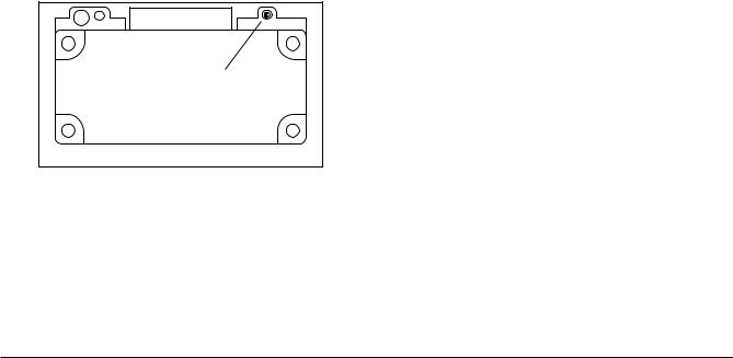
Inserting the batteries
To insert new batteries, you must first loosen the four screws at the bottom of the instrument (see following figure) and then remove the battery compartment lid.
Each battery in the battery pack is secured with a separate holder.
AAttention:
When inserting the batteries, make sure that the polarities are correct and that the switch in the battery compartment is set to the type of battery being used!
Nickel Cadmium (NiCd): |
left |
Alkaline (Alk): |
right |
This ensures that only rechargeable batteries are charged.
Krautkramer USN 52R/USN 52L |
Issue 05, 02/00 |
3-3 |
Setting into operation |
Positioning the USN 52R/USN 52L |
Using the battery charger
The power supply/charger unit for USN 52R/USN 52L automatically adjusts itself fo the existing supply voltage in the range from 80 to 250 V.
The connection for the combined power supply/charger unit is at the rear of the instrument (see following figure).
Connection supply/battery charger
When using the power supply/charger unit you are able to simultaneously charge NiCd cells in the USN 52 R and operate the instrument. The power supply/charger unit requires 4 to 7 hours in order to fully charge the NiCd cells.
The green LED indicates that the power supply/charger unit is connected to mains.
The yellow LED of the power supply/charger unit indicates the operational status:
LED |
Status |
LED off |
- instrument is switched off |
|
- no NiCd batteries in the |
|
insturment |
|
- instrument is set to AlMn |
|
|
LED on |
- instrument is switched on |
|
- NiCd batteries are being |
|
charged |
|
|
LED flashes |
- instrument is switched off |
|
- NiCd batteries are fully |
|
charged (trickle charge) |
AAttention:
If you have inserted AlMn cells and the switch is set to NiCd, the internal charge of the cells will be isolated. In this case, the AlMn cells will become quickly hot and the pressure in the cells will cause a leakage of electrolyte after a short period of time. This strongly caustic fluid can damage the instrument!
Only use the batteries that we recommend. There is a danger of explosion if the charger and the batteries are incorrectly used.
3-4 |
Issue 05, 02/00 |
Krautkramer USN 52R/USN 52L |

Probe connection
Setting into operation
3.3 Probe connection |
3.4 Starting the USN 52 R |
The probe connections are on the lower right of the front panel.
Connect straight-beam probes to the red socket (Receive - right). With T/R probes, connect the pulser cable to the green socket (left) and the receiver cable to the red socket (right).
–Set the pulser power as follows:
–Switch the USN 52 R on with K.
–Select the function group RCVR by pressing C.
–Using Nor O, set the damping resistor in function DAMPING There are 4 settings available: 50, 75, 150 and 1000 ohms.
Switching on
This is the normal way of switching on the USN 52 R.
–Press the switch-on key K in the operator’s control panel.
After a short time, the start display appears with information about the applied software version and about the instrument configuration.
The settings for all function values and default settings are the same as before switching off.
Krautkramer USN 52R/USN 52L |
Issue 05, 02/00 |
3-5 |
 Loading...