


NX125
Table of contents
 Loading...
Epson NX125, NX127, TX120, TX125, TX123 Service manual
...
SERVICE MANUAL
CONFIDENTIAL
Color Inkjet Printer
Epson Stylus NX125/NX127/TX120/TX125/TX123/
SX125/TX121/TX121x/TX129/
Epson ME 320/ME 330/ME 350
Epson Stylus T13/T13x/T12/N10/N11/T22/T25/S22/
T22E/
Epson ME 10/ME 32/ME 33/ME 35
Epson Stylus NX130/TX130/TX133/TX135/SX130
ME 340
SEMF09-013
SEIJ09-007

Confidential
Notice:
All rights reserved. No part of this manual may be reproduced, stored in a retrieval system, or transmitted in
any form or by any means, electronic, mechanical, photocopying, recording, or otherwise, without the prior
written permission of SEIKO EPSON CORPORATION.
All effort have been made to ensure the accuracy of the contents of this manual. However, should any errors
be detected, SEIKO EPSON would greatly appreciate being informed of them.
The contents of this manual are subject to change without notice.
The above not withstanding SEIKO EPSON CORPORATION can assume no responsibility for any errors in
this manual or the consequences thereof.
EPSON is a registered trademark of SEIKO EPSON CORPORATION.
Note :Other product names used herein are for identification purpose only and may be trademarks or r egistered
trademarks of their respective owners. EPSON disclaims any and all rights in those marks.
Copyright 2010 SEIKO EPSON CORPORATION
IJP CS Quality Assurance Department

Confidential
Safety Precautions
All safety procedures described here shall be strictly adhered to by all parties servicing and maintaining this
product.
DANGER
Strictly observe the following cautions. Failure to comply could result in serious bodily injury or loss of life.
1. Always disconnect the product from the power source and peripheral devices when servicing the product or
performing maintenance.
2. When performing works described in this manual, do not connect to a power source until instructed to do so.
Connecting to a power source causes high voltage in the power supply unit and some electronic components
even if the product power switch is off. If you need to perform the work with the power cable connected to a
power source, use extreme caution to avoid electrical shock.
WARNING
Strictly observe the following cautions. Failure to comply may lead to personal injury or loss of life.
1. Always wear protective goggles for disassembly and reassembly to protect your eyes from ink in working. If
any ink gets in your eyes, wash your eyes with clean water and consult a doctor immediately.
2. When using compressed air products; such as air duster, fo r cleaning during repair and maintenance, the use
of such products containing flammable gas is prohibited.
PRECAUTIONS
Strictly observe the following cautions. Failure to comply may lead to personal injury or damage of the product.
1. Repairs on Epson product should be performed only by an Epson certified repair technician.
2. No work should be performed on this product by persons unfamiliar with basic safety knowledge required for
electrician.
3. The power rating of this product is indicated on the serial number/rating plate. Never connect this product to
the power source whose voltages is different from the rated voltage.
4. Replace malfunctioning components only with those components provided or approved by Epson;
introduction of second-source ICs or other non-approved components may damage the product and void any
applicable Epson warranty.
5. In order to protect sensitive microprocessors and circuitry, use static discharge equipment, such as anti-static
wrist straps, when accessing internal components.
6. Do not tilt this product immediately after initial ink charge, especially after performing the ink charge several
times. Doing so may cause ink to leak from the product because it may take some time for the waste ink pads
to completely absorb ink wasted due to the ink charge.
7. Never touch the ink or wasted ink with bare hands. If ink comes into contact with your skin, wash it off with
soap and water immediately. If you have a skin irritation, consult a doctor immediately.

Confidential
8. When disassembling or assembling this product, make sure to wear gloves to avoid injuries from metal parts
with sharp edges.
9. Use only recommended tools for disassembling, assembling or adjusting the printer.
10. Observe the specified torque when tightening screws.
11. Be extremely careful not to scratch or contaminate the following parts.
Nozzle plate of the printhead
CR Scale
PF Scale
Coated surface of the PF Roller
Gears
Rollers
LCD
Scanner Sensor
Exterior parts
12. Never use oil or grease other than those specified in this manual. Use of different types of oil or grease may
damage the component or give bad influence on the printer function.
13. Apply the specified amount of grease described in this manua l .
14. Make the specified adjustments when you disassemble the printer.
15. When cleaning this product, follow the procedure described in this manual.
16. When transporting this product after filling the ink in the printhead, pack the printer without removing the
ink cartridges in order to prevent the printhead from drying out.
17. Make sure to install antivirus software in the computers used for the service support activities.
18. Keep the virus pattern file of antivirus software up-to-date.
Confidential
About This Manual
This manual, consists of the following chapters, is intended for repair service personnel and includes information
necessary for properly performing maintenance and servicing the product.
CHAPTER 1. DISASSEMBLY / ASSEMBLY
Describes the disassembly/reassembly procedures for main parts/units of the product, and provides the
standard operation time for servicing the product.
CHAPTER 2. ADJUSTMENT
Describes the required adjustments for servicing the product.
CHAPTER 3. MAINTENANCE
Describes maintenance items and procedures for servicing the product.
CHAPTER 4. APPENDIX
Provides the following additional information for reference:
Power-On Sequence
Connector Summary
Symbols Used in this Manual
Various symbols are used throughout this manual either to provide additional information on a specific topic or
to warn of possible danger present during a procedure or an action. Pay attention to all symbols when they are
used, and always read explanation thoroughly and follow the instructions.
Indicates an operating or maintenance procedure, practice or condition that, if not strictly observed,
could result in serious injury or loss of life.
Indicates an operating or maintenance procedure, practice, or condition that, if not strictly observed,
could result in bodily injury, damage or malfunction of equipment.
May indicate an operating or maintenance procedure, practice or condition that is necessary to
accomplish a task efficiently. It may also provide additional information that is related to a specific
subject, or comment on the results achieved through a previous action.
For Chapter 1 “Disassembly/Assembly”, symbols other than indicated above are used to show additional
information for disassembly/reassembly. For the details on those symbols, see " 1.2 Disassembly/Assembly
Procedures (p10)".

Confidential
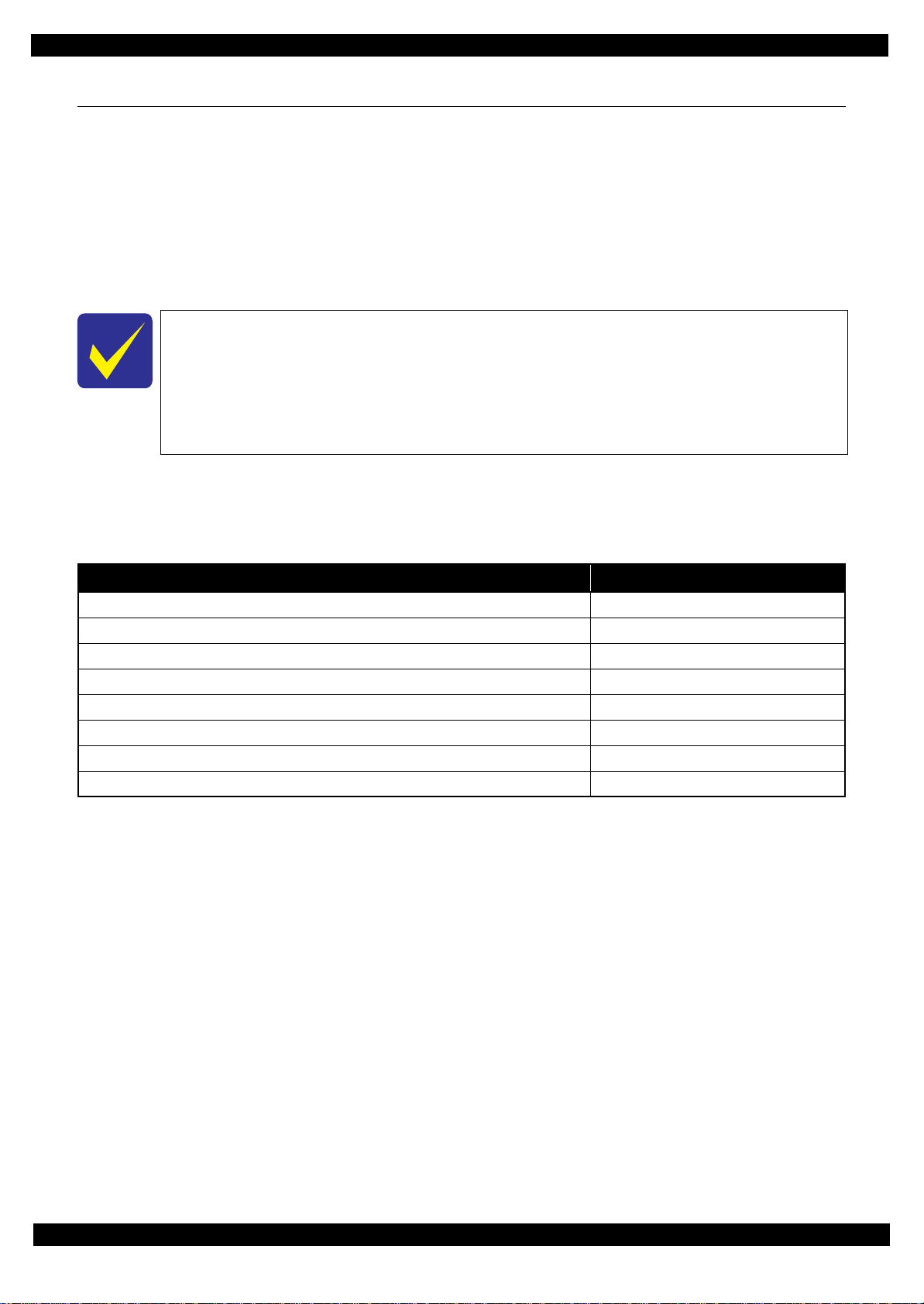
Revision Status
Revision Date of Issue Description
A April 28, 2010 First Release
B August 19, 2010 Revised Contents
[Chapter 1]
- 1.2.1Standard Operation Time for servicing the product Table 1-2 on page 11-12
Standard Operation Time(NX125 series) is added.
- 1.2.1Standard Operation Time for servicing the product Table 1-3 on page 12
Standard Operation Time(T13 series) is added.
[Chapter 3]
- 3-1 Overview on page 28-30.
Greese name is added.
C October 12, 2010 [Chapter 3]
- 3-1 Overview on page 28-30.
Greese name is TBD.
D February 22, 2011 [All chapters]
The model name”EPSON Stylus TX121x/TX13x/EPSON ME 350/
EPSON ME 35 are added.
E March 25, 2011 Revised Contents
[All chapters]
- The model name ”EPSON Stylus NX130 series” are added, and revision is changed.
[Chapter 5]
- Information for “EPSON Stylus NX130/TX130/TX133/TX135/SX130/ME340” is
added.
F May 26, 2011 Revised Contents
[chapter 3]
- 3-1 Overview on page 28.
Grease name: G-94
- 3-2 Overview on page 29.
<Grease Lubrication Point>
Shaft on the Scanner Housing ---> Greese name is G-94.
- 3-2 Overview on page 30.
<Grease Lubrication Point>
Contacting points (x2) with the Driven Pulley ---> Greese name is G-71.

7
Epson Stylus NX125/T13/NX130 series Revision F
Confidential
Contents
Chapter 1 Disassembly/Assembly
1.1 O verview ................................................................................................................................................................... 9
1.1.1 Tools ................................................................................................................................................................. 9
1.2 D isassembly/Assembly Procedures......................................................................................................................... 10
1.2.1 Standard Operation Time for servicing the product ....................................................................................... 11
1.2.2 D isassembling/Assembling Flowchart ........................................................................................................... 13
1.2.2.1 Housing Part .................................. .................................... ... ................................................................. 13
1.2.2.2 Printer Mechanism Part ......................................................................................................................... 14
1.3 Details of Disassembling/Assembling by Parts/Unit .............................................................................................. 16
1.4 Routing FFC/cables................................................................................................................................................. 21
Chapter 2 Adjustment
2.1 Required Adjustments ............................................................................................................................................. 24
2.2 Revision EDetails of Adjustments .......................................................................................................................... 26
2.2.1 TOP Margin Adjustment ................................................................................................................................ 26
Chapter 3 Maintenance
3.1 O verview ................................................................................................................................................................. 28
3.1.1 Cleaning.......................................................................................................................................................... 28
3.1.2 Lubrication...................................................................................................................................................... 28
3.2 Lubrication Point.............................. ..................................... ..................................... ............................................. 29
Chapter 4 Appendix
4.1 Power-On Sequence ................................................................................................................................................ 32
4.2 Connector Summary................................................................................................................................................ 34
Chapter 5 Stylus NX130 Series
5.1 O verview ................................................................................................................................................................. 36

Confidential
CHAPTER 1
DISASSEMBLY/ASSEMBLY
Confidential
Disassembly/Assembly Overview 9
Epson Stylus NX125/T13/NX130 series Revision F
1.1 Overview
This chapter describes procedures for disassembling the main components of NX125, T13 and NX130 series.
Unless otherwise specified, disassembled units or components can be reassembled by reversing the disassembly
procedure. Refer to " 1.3 Details of Disassembling/Assembling by Parts/Unit (p16)" for cautions and such if
necessary when disassembling and assembling.
Read the " Safety Precautions (p3)" before disassembling and assembling.
When you have to remove components or parts that are not described in this chapter, see the exploded diagrams
of SPI (Service Parts Information).
1.1.1 Tools
Use only specified tools to avoid damaging the printer.
Note *: All of the tools listed above are commercially available.
EPSON provides the tools listed with EPSON part code.
In this chapter, the product names are called as follows:
NX125 series: Epson Stylus NX125/NX127/TX120/TX125/TX123/SX125/TX121/TX121x/
TX129/Epson ME 320/ME 330/ME 350
T13 series: Epson Stylus T13/T13x/T12/N10/N11/T22/T25/S22/T22E/Epson ME 10/
ME 32/ME 33/ME 35
NX130 series: Epson Stylus NX130/TX130/TX133/TX135/SX130/Epson ME 340
Table 1-1. Tools
Name EPSON Part Code*
(+) Phillips screwdriver #1 1080530
(+) Phillips screwdriver #2 ---
Flathead screwdriver ---
Flathead Precision screwdriver #1 ---
Tweezers ---
Longnose pliers ---
Acetate tape 1003963
Nippers ---
Confidential
Disassembly/Assembly Disassembly/Assembly Procedures 10
Epson Stylus NX125/T13/NX130 series Revision F
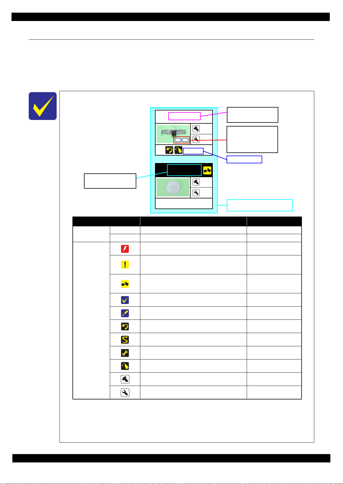
1.2 Disassembly/Assembly Procedures
This section describes procedures for disassembling the parts/units in a flowchart form. For some parts/units,
detailed procedures or precautions are provided (accordingly indicated by icons and cell's color). Refer to the
explanations in the example chart below and perform an appropriate disassembling and assembling procedure.
(See" 1.3 Details of Disassembling/Assembling by Parts/Unit (p16)".)
For routing cables, see " 1.4 Routing FFC/cables (p21)"
The example below shows how to see the charts on the following pages.
Main Frame
4
5
(p 17, p 29)
S1
S5
EJ Roller Gear
---
---
---
Item Description Reference
Parts/unit name
White-letter
Parts/units supplied as an ASP ---
Black-letter
Parts/units not supplied as an ASP ---
Icon
Indicates a practice or condition that could result in
injury or loss of life if not strictly observed.
Indicates the reference
page in blue-letter
Indicates a practice or condition that could result in
damage to, or destruction of equipment if not strictly
observed.
Indicates the reference
page in blue-letter
Indicates the parts that are inevitably broken in the
disassembling procedure, and should be replaced with
a new one for reassembly.
---
Indicates necessary check items in the disassembling/
assembling procedure.
Indicates the reference
page in blue-letter
Indicates supplementary explanation for disassembly
is given.
Indicates the reference
page in blue-letter
Indicates particular tasks to keep quality of the
components are required.
Indicates the reference
page in blue-letter
Indicates particular routing of cables is required.
Indicates the reference
page in blue-letter
Indicates particular adjustment(s) is/are required.
Chapter 2 " Adjustment
(p23)"
Indicates lubrication is required.
Chapter 3 " Maintenance
(p27)"
Indicates the number of screws securing the parts/
units.
---
Indicates the points secured with other than a screw
such as a hook, rib, dowel or the like.
---
Shows removal/installation as a
unit/assy. is available.
Reference page
White letters indicate a
part/unit supplied as an
ASP.
Black letters indicate a
part/unit not supplied
as an ASP.
Shows the
correspondence to the
screw types and the
specified torque in the
"Screw type/torque list".
Confidential
Disassembly/Assembly Disassembly/Assembly Procedures 11
Epson Stylus NX125/T13/NX130 series Revision F
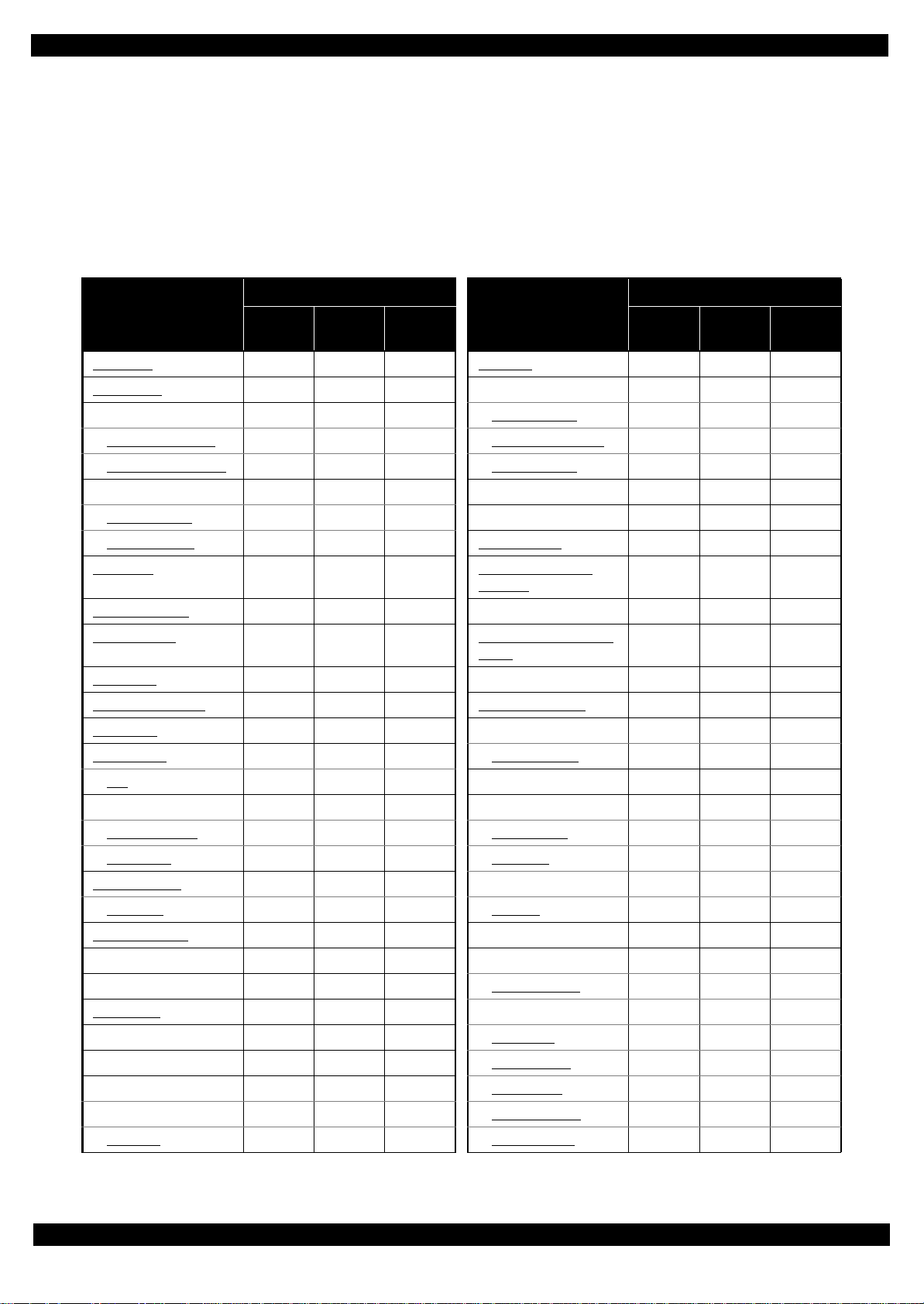
1.2.1 Standard Operation Time for servicing the product
The following are the standard operation time for servicing the product. Those are based on the MTTR result
measured using a prototype.
The underlined parts/units are supplied as After Service Parts.
Standard Operation Time for servicing NX125/NX130 series :See Table 1-2.
Standard Operation Time for servicing T13 series:: :::: :See Table 1-3.
Table 1-2. Standard Operation Time (NX125/NX130 series)
Parts/Unit
Time (second)
Parts/Unit
Time (second)
Replace-
ment
Adjust-
ment
Total
Replace-
ment
Adjust-
ment
Total
Panel Unit
14519Printhead 364 1027 1391
Panel Board
29 5 34 Holder Contact Assy 179 1027 1206
Paper Support Assy 12 5 17 CSIC Terminal
221 1027 1248
Paper Support Tray
20 5 25 CR Contact Module 194 1027 1221
Paper Support Tray 2
26 5 31 Holder Contact 293 1027 1320
Stacker Assy 12 5 17 EJ Frame Assy 149 5 154
Tray Exit Inner
15 5 20 EJ Roller 170 768 938
Tray Exit Outer
18523EJ Roller Gear 134 768 902
Jam Cover
18523
Waste Ink Pads (for
flushing)
230 768 998
Document Cover
9 5 14 Cover Flushing 195 768 963
Document Pad
20525
Porous Pad Front Paper
Guide
159 5 164
ASF Cover
5 5 10 CR Motor 235 768 1003
Ink Cartridge Cover
18 5 23 Power Supply Unit 129 768 897
Rear Cover
10 5 15 Waste Ink Tray Assy 163 822 985
Scanner Unit
79 5 84 Waste Ink Pads 239 822 1061
CIS
245 5 250 Main Frame 501 768 1269
Middle Housing Assy 126 5 131 Carriage Assy 906 768 1674
Middle Housing
146 5 151 PCB Encoder 953 768 1721
USB Cover
146 5 151 Head FFC 939 768 1707
LD Roller Assy
186 768 954 Timing Belt 915 768 1683
LD Roller
227 768 995 Carriage 995 768 1763
Housing Buckler
183 5 188 Upper Paper Guide 269 768 1037
Roller Idler Pick Assy 160 5 165 Pump Assy 791 768 1559
CR Scale 181 5 186 Gear Pump Idle
797 768 1565
Main Board
150 1027 1177 Lever Pick Clutch 798 768 1566
Driven Pulley Assy 363 768 1131 Gear Pump
811 768 1579
Pick Assy 376 768 1144 Bracket Pump
832 768 1600
Cap Unit 481 768 1249 Roller Pump
827 768 1595
Lever Cleaner 175 768 943 Waste Ink Tube
892 768 1640
Cap Assy
449 768 1217 Pump Housing 892 768 1660
Loading...