


EPSON
IMPACT SERIAL DOT MATRIX PRINTER
DFX-8500
SERVICE MANUAL
SEIKO EPSON CORPORATION
4009310
NOTICE
ƒ All rights reserved. Reproduction of any part of this manual in any form whatsoever without SEIKO EPSON’s express written permission is forbidden.
ƒ The contents of this manual are subjects to change without notice.
ƒ All efforts have been made to ensure the accuracy of the contents of this manual. However, should any errors be detected, SEIKO EPSON would greatly appreciate being informed of them.
ƒ The above notwithstanding SEIKO EPSON can assume no responsibility for any errors in this manual or the consequences thereof.
EPSON is a registered trademark of SEIKO EPSON CORPORATION.
General Notice:
Other product names used herein are for identification purposes only and may be trademarks or registered trademarks of their respective companies.
Copyright ã 1998 by SEIKO EPSON CORPORATION
Nagano, Japan
ii
PRECAUTIONS
Precautionary notations throughout the text are categorized relative to 1) personal injury and 2) damage to equipment.
WARNING Signals a precaution which, if ignored, could result in serious or fatal personal injury. Great caution should be exercised in performing procedures preceded by WARNING Headings.
CAUTION Signals a precaution which, if ignored, could result in damage to equipment.
The precautionary measures itemized below should always be observed when performing repair/maintenance procedures.
WARNING
1.ALWAYS DISCONNECT THE PRODUCT FROM BOTH THE POWER SOURCE AND PERIPHERAL DEVICES PERFORMING ANY MAINTENANCE OR REPAIR PROCEDURES.
2.NO WORK SHOULD BE PERFORMED ON THE UNIT BY PERSONS UNFAMILIAR WITH BASIC SAFETY MEASURES AS DICTATED FOR ALL ELECTRONICS TECHNICIANS IN THEIR LINE OF WORK.
3.WHEN PERFORMING TESTING AS DICTATED WITHIN THIS MANUAL. DO NOT CONNECT THE UNIT TO A POWER SOURCE UNTIL INSTRUCTED TO DO SO. WHEN THE POWER SUPPLY CABLE MUST BE CONNECTED, USE EXTREME CAUTION IN WORKING ON POWER SUPPLY AND OTHER ELECTRONIC COMPONENTS.
CAUTION
1.REPAIRS ON EPSON PRODUCT SHOULD BE PERFORMED ONLY BY EPSON CERTIFIED REPAIR TECHNICIAN.
2.MAKE CERTAIN THAT THE SOURCE VOLTAGE IS THE SAME AS THE RATED VOLTAGE, LISTED ON THE SERIAL NUMBER/RATING PLATE. IF THE EPSON PRODUCT HAS A PRIMARY AC RATING DIFFERENT FROM AVAILABLE POWER SOURCE, DO NOT CONNECT IT TO THE POWER SOURCE.
3.ALWAYS VERIFY THAT THE EPSON PRODUCT HAS BEEN DISCONNECTED FROM THE POWER SOURCE BEFORE REMOVING OR REPLACING PRINTED CIRCUIT BOARDS AND/OR INDIVIDUAL CHIPS.
4.IN ORDER TO PROTECT SENSITIVE MICROPROCESSORS AND CIRCUITRY, USE STATIC DISCHARGE EQUIPMENT, SUCH AS ANTI-STATIC WRIST STRAPS, WHEN ACCESSING INTERNAL COMPONENTS.
5.REPLACE MALFUNCTIONING COMPONENTS ONLY WITH THOSE COMPONENTS BY THE MANUFACTURE; INTRODUCTION OF SECOND-SOURCE ICs OR OTHER NONAPPROVED COMPONENTS MAY DAMAGE THE PRODUCT AND VOID ANY APPLICABLE EPSON WARRANTY.
iii
PREFACE
This manual describes functions, theory of electrical and mechanical operations, maintenance, and repair of DFX-8500.
The instructions and procedures included herein are intended for the experience repair technician, and attention should be given to die precautions on the preceding page. The Chapters are organized as follows:
CHAPTER 1. GENERAL DESCRIPTION
Provides a general product overview, lists specifications, and illustrates the main components of the printer.
CHAPTER 2. OPERATING PRINCIPLES
Describes the theory of printer operation.
CHAPTER 3. DISASSEMBLY AND ASSEMBLY
Includes a step-by-step guide for product disassembly and assembly.
CHAPTER 4. ADJUSTMENT
Includes a step-by-step guide for adjustment.
CHAPTER 5. TROUBLESHOOTING
Provides EPSON-approved techniques for troubleshooting.
CHAPTER 6. MAINTENANCE
Describes preventive maintenance techniques and lists lubricants and adhesives required to service the equipment.
APPENDIX
Describes connector pin assignments, circuit diagrams, circuit board component layout and exploded diagram.
The contents of this manual are subject to change without notice.
iv
REVISION SHEET
Revision |
Issued Data |
Contents |
Rev. A |
May 18, 1998/ |
First issue |
Rev. B |
June 25, 1998 |
Second issue due to minor correction on the |
|
|
manual contents. |
|
|
|
|
|
|
|
|
|
|
|
|
v
TABLE OF CONTENTS
CHAPTER 1. |
GENERAL DESCRIPTION |
CHAPTER 2. |
OPERATING PRINCIPLES |
CHAPTER 3. |
DISASSEMBLY AND ASSEMBLY |
CHAPTER 4. |
ADJUSTMENT |
CHAPTER 5. |
TROUBLESHOOTING |
CHAPTER 6. |
MAINTENANCE |
APPENDIX |
|
vi
|
CHAPTER 1 |
GENERAL DESCRIPTION |
|
|
|
1.1 FEATURES............................................................................................................. |
1-1 |
1.2 SPECIFICATIONS.................................................................................................. |
1-3 |
1.2.1 Printing Specification............................................................................................................. |
1-3 |
1.2.2 Paper Feeding ......................................................................................................................... |
1-6 |
1.2.3 Electrical Specification .......................................................................................................... |
1-6 |
1.2.4 Environmental Condition....................................................................................................... |
1-6 |
1.2.5 Reliability................................................................................................................................. |
1-6 |
1.2.6 Safety Approvals .................................................................................................................... |
1-7 |
1.2.7 CE Marking .............................................................................................................................. |
1-7 |
1.2.8 Acoustic Noise........................................................................................................................ |
1-7 |
1.2.9 Ribbon Cartridge .................................................................................................................... |
1-7 |
1.2.10 Physical Specifications........................................................................................................ |
1-7 |
1.2.11 Printable area ........................................................................................................................ |
1-8 |
1.2.12 Paper and Media ................................................................................................................. |
1-12 |
1.2.12.1 Continuous paper (Single sheet and multi-part).................................................... |
1-12 |
1.2.12.2 Labels .................................................................................................................... |
1-14 |
1.2.12.3 Continuous Forms with Labels .............................................................................. |
1-14 |
1.2.12.4 Overlapping Multi-part Form.................................................................................. |
1-16 |
1.2.12.5 Perforation............................................................................................................. |
1-16 |
1.2.12.6 Notes ..................................................................................................................... |
1-16 |
1.3 INTERFACES ....................................................................................................... |
1-19 |
1.3.1 Parallel Interface (Forward channel)................................................................................... |
1-19 |
1.3.2 Parallel Interface (Reverse channel)................................................................................... |
1-21 |
1.3.3 Serial Interface ...................................................................................................................... |
1-22 |
1.3.4 Optional Interface ................................................................................................................. |
1-22 |
1.3.5 Interface Selection................................................................................................................ |
1-23 |
1.3.6 Prevention Hosts from Data Transfer Time-out................................................................. |
1-23 |
1.4 OPERATING INSTRUCTIONS............................................................................. |
1-24 |
1.4.1 Control Panel ........................................................................................................................ |
1-24 |
1.4.1.1 Switches .................................................................................................................. |
1-25 |
1.4.1.2 Indicators................................................................................................................. |
1-26 |
1.4.2 Errors and Buzzers............................................................................................................... |
1-27 |
1.4.3 DIP Switch Settings.............................................................................................................. |
1-28 |
1.4.4 Functions .............................................................................................................................. |
1-31 |
1.4.4.1 Usual operation ....................................................................................................... |
1-31 |
1.4.4.2 Operation at Power On............................................................................................ |
1-33 |
1.4.4.3 Built-in Detection ..................................................................................................... |
1-34 |
1.4.5 Paper Memory Function....................................................................................................... |
1-35 |
1.4.6 Initializations......................................................................................................................... |
1-36 |
1.4.6.1 Power-on Initialization ............................................................................................. |
1-36 |
1.4.6.2 Software Initialization............................................................................................... |
1-36 |
1.4.6.3 Panel Initialization.................................................................................................... |
1-36 |
1.5 MAIN COMPONENT ........................................................................................... |
1-37 |
1.5.1 M-3I60 Printer Mechanism ................................................................................................... |
1-38 |
1.5.2 Main Control Board (C204 MAIN Board)............................................................................. |
1-39 |
1.5.3 C204 DRV Board ................................................................................................................... |
1-40 |
1.5.4 C204 DRV-B Board................................................................................................................ |
1-41 |
1.5.5 C204 SUB Board.................................................................................................................... |
1-41 |
1.5.6 C204 PSB/PSE Board............................................................................................................ |
1-42 |
1.5.7 Control Panel......................................................................................................................... |
1-43 |
1.5.8 Housing.................................................................................................................................. |
1-43 |
GENERAL DESCRIPTION
1.1 FEATURES
The DFX-8500 is a 18-pin, serial, dot matrix printer with a maximum speed of 1120 characters per second (cps). It is designed for business use and provides high-speed, high-volume printing and continuous-sheet handling. The main features of the printer are:
‰ Maximum printing speeds:
„ 1120 cps (high-speed draft mode) „ 840 cps (draft mode)
„ 210 cps (NLQ mode) at 10 cpi ‰ Advanced paper handling:
„ 10 inches per second (ips) paper feeding „ Paper jam detection
„ Paper width detection
„ Front and rear two-way push tractors „ Optional pull tractor
„ Automatic paper back-out and loading from another paper path and paper park „ Automatic platen gap adjustment for paper thickness
„ Automatic tear off
„ Paper memory function
„ Automatic paper path changing
„ Auto cut mode enables the optional perforation cutter to cut the paper at the perforation. ‰ Bi-directional parallel interface (IEEE-1284 nibble) and RS-232C serial interface standard ‰ EPSON ESC/P (upper compatible with DFX-8000) and IBM/LEXMARK 2381Plus emulation
‰ 35 character tables in the NLSP (National Language Support) version and 11 character tables in the standard version
‰ 2 NLQ and 1 draft bit-map type faces and 8 barcode fonts are supported. ‰ Optional paper cutter and perforation cutter
‰ Upgraded data handling „ 128 KB input buffer
„ Automatic interface selection „ Type-B optional I/F cards
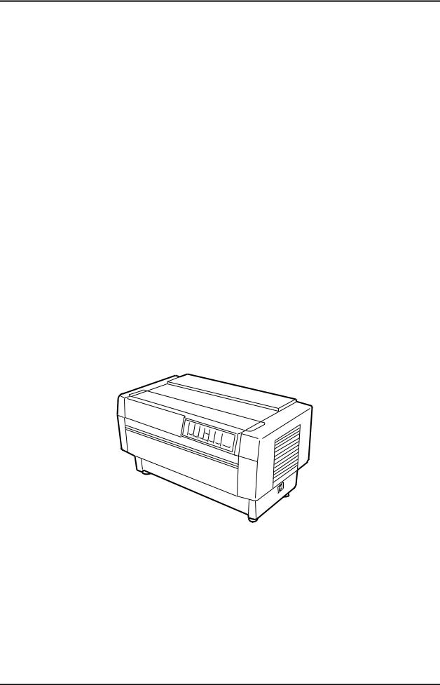
The figure below shows the DFX-8500.
Figure 1-1. DFX-8500 Exterior View
Rev. B |
1-1 |

DFX-8500
The following table shows options.
|
Table 1-1. Option |
|
Code |
|
Name |
#8766 |
|
Ribbon cartridge |
#8767 |
|
Ribbon pack |
#8309 |
|
Pull tractor unit |
C81500X |
|
Paper cutter |
C81507X |
|
Perforation cutter |
C82305* |
|
Serial interface card (inch screw) |
C82306* |
|
Serial interface card (mm screw) |
C82307* |
|
32-KB intelligent serial I/F card (inch screw) |
C82308* |
|
32-KB intelligent serial I/F card (mm screw) |
C82310* |
|
32-KB intelligent parallel I/F card (inch screw) |
C82311* |
|
32-KB intelligent parallel I/F card (mm screw) |
C82312* |
|
Local Talk I/F card |
C82313* |
|
32KB IEEE-488 I/F card |
C82314* |
|
Coax I/F card |
C82315* |
|
Twinax I/F card |
C82357* |
|
Ethernet I/F card |
C82345* |
|
IEEE-1284 parallel I/F card |
C82362 |
|
Ethernet I/F card |
C82364 |
|
Ethernet I/F card |
1-2 |
Rev. B |
|
GENERAL DESCRIPTION
1.2 SPECIFICATIONS
This section describes the specifications for DFX-8500.
1.2.1 Printing Specification
‰ |
Print method |
: |
Impact dot matrix |
|
‰ |
Number of pins |
: 18-pin (Refer to Figure 1-2.) |
||
‰ |
Print pin arrangement |
: |
9 x 2 |
|
‰ |
Print pin diameter |
: 0.0114 inches (0.29 mm) |
||
‰ |
Color |
: |
Black |
|
‰ |
Print direction |
: Bi-directional with logic seeking |
||
‰ |
Print speed and printable columns: |
Refer to Table 1-2. |
||
0.35 mm (1/72") |
2.82 mm (8/72") |
1.69 mm (1/15") |
Figure 1-2. Printhead Pin Configuration
Table 1-2. Print Speed and Printable Columns
Print Mode |
Character Pitch |
Printable Columns |
Print Speed (cps) |
|
|
|
|
Normal |
High Duty |
High speed draft |
10 cpi |
136 |
1120 |
1066 |
Draft |
10 cpi |
136 |
840 |
800 |
|
12 cpi |
163 |
1008 |
960 |
|
15 cpi |
204 |
630 |
630 |
Draft condensed |
17 cpi |
233 |
720 |
685 |
|
20 cpi |
272 |
840 |
800 |
Draft emphasized |
10 cpi |
136 |
420 |
400 |
NLQ |
10 cpi |
136 |
210 |
200 |
|
12 cpi |
163 |
252 |
240 |
|
15 cpi |
204 |
200 |
200 |
NLQ condensed |
17 cpi |
233 |
171 |
171 |
|
20 cpi |
272 |
200 |
200 |
Notes 1: The line including graphic B0h - FFh or download characters or bit image data will be printed by “High duty" mode.
Notes 2: The line including special high duty download characters or bit image data will be printed by one third speed of “High duty” mode.
Notes 3: When the print head temperature rises to the upper limit, the printer stops printing. And when the print head temperature falls to the normal level, then the printer starts printing again.
Rev. B |
1-3 |

DFX-8500 |
|
|
|
|
|
|
||
‰ |
Resolution: |
Refer to Table 1-3. |
|
|
|
|
||
|
|
|
Table 1-3. Resolution |
|
||||
Print Mode |
|
Horizontal Density |
|
Vertical Density |
|
Adjacent Dot Print |
||
High speed draft |
|
90 dpi |
|
|
72 dpi |
|
No |
|
Draft |
|
|
120 dpi |
|
|
72 dpi |
|
No |
Draft condensed |
|
240 dpi |
|
|
72 dpi |
|
No |
|
Draft emphasized |
|
120 dpi |
|
|
72 dpi |
|
Yes |
|
NLQ |
|
|
240 dpi |
|
|
144 dpi |
|
No |
|
|
60, 72, 80, 90, 120 or 144 |
|
|
72 dpi |
|
Yes |
|
Bit image |
|
dpi |
|
|
|
|
|
|
|
|
|
120 or 240 dpi |
|
|
72 dpi |
|
No |
‰ |
Control code: |
ESC/P and IBM 2381 Plus emulation |
|
|||||
‰ |
Character tables: |
|
|
|
|
|||
„ Standard version (11 character tables): |
|
|
|
|
||||
|
|
|
Italic table |
|
PC437 (US, Standard Europe) |
|||
|
|
|
PC850 (Multilingual) |
|
PC860 (Portuguese) |
|||
|
|
|
PC861 (Icelandic) |
|
PC863 (Canadian-French) |
|||
|
|
|
PC865 (Nordic) |
|
Abicomp |
|
||
|
|
|
BRASCII |
|
Roman 8 |
|
||
|
|
|
ISO Latin 1 |
|
|
|
|
|
„ NLSP version (35 character tables): |
|
|
|
|
||||
|
|
|
Italic table |
|
PC437 (US, Standard Europe) |
|||
|
|
|
PC850 (Multilingual) |
|
PC437 Greek |
|
||
|
|
|
PC852 (East Europe) |
|
PC853 (Turkish) |
|
||
|
|
|
PC855 (Cyrillic) |
|
PC857 (Turkish ) |
|
||
|
|
|
PC866 (Russian) |
|
PC869 (Greek) |
|
||
|
|
|
MAZOIWA (Poland) |
|
Code MJK (CSFR) |
|||
|
|
|
ISO 8859-7 (Latin / Greek) |
ISO Latin 1T (Turkish) |
||||
|
|
|
Bulgaria (Bulgarian) |
|
Estonia (Estonia) |
|||
|
|
|
PC 774 (LST 1283:1993) |
ISO 8859-2 (ISO Latin 2) |
||||
|
|
|
PC 866 LAT. (Latvian) |
|
PC866 UKR |
|
||
|
|
|
PC 860 |
|
PC 861 |
|
||
|
|
|
PC 865 |
|
PC APTEC |
|
||
|
|
|
PC 708 |
|
PC 720 |
|
||
|
|
|
PC AR864 |
|
PC 863(Canadian French) * |
|||
|
|
|
Abicomp* |
|
BRASCII* |
|
||
|
|
|
Roman 8* |
|
ISO Latin 1* |
|
||
|
|
|
Hebrew 7* |
|
Hebrew 8* |
|
||
|
|
|
PC862* |
|
|
|
|
|
Note: These tables can not be selected by DIP switch.
„ International character sets : 13 countries |
|
|
||
|
USA |
France |
|
Germany |
|
U.K |
Denmark 1 |
Sweden |
|
|
Italy |
Spain 1 |
|
Japan |
|
Norway |
Denmark 2 |
Spain 2 |
|
|
Latin America |
|
|
|
Note : The international and legal characters are these 12 codes; |
||||
|
23h, 24h, 40h, 5Bh, 5Ch, 5Dh, 5Eh, 60h, 7Bh, 7Ch, 7Dh, 7Eh. |
|||
‰ Typeface: |
|
|
|
|
„ |
Bit map font: |
|
|
|
|
EPSON Draft |
|
10 CPI, 12 CPI, 15 CPI |
|
|
EPSON Roman |
10 CPI. 12 CPI, 15 CPI, Proportional |
||
|
EPSON Sans Serif |
10 CPI, 12 CPI, 15 CPI, Proportional |
||
„ |
Bar code: |
|
|
|
|
EAN-13 |
|
EAN-8 |
|
|
Interleaved 2 of 5 |
UPC-A |
|
|
|
UPC-E |
|
Code 39 |
|
|
Code 128 |
|
POSTNET |
|
1-4 |
Rev. B |
|

|
|
|
GENERAL DESCRIPTION |
‰ Character tables and type faces: |
Refer to Table 1-4. |
|
|
|
Table 1-4. Character tables and type faces |
|
|
|
Character Table |
Bitmap Font |
|
Standard version |
Italic Table |
|
EPSON Draft |
|
PC437 (US, Standard Europe) |
EPSON Roman |
|
|
PC850 (Multilingual) |
|
EPSON Sans Serif |
|
PC860 (Portuguese) |
|
|
|
PC861 (Icelandic) |
|
|
|
PC863 (Canadian French) |
|
|
|
PC865 (Nordic) |
|
|
|
Abicomp |
|
|
|
BRASCII |
|
|
|
Roman 8 |
|
|
|
ISO Latin 1 |
|
|
|
Italic table |
|
|
NLSP version |
Italic Table |
|
EPSON Draft |
|
PC437 (US, Standard Europe) |
EPSON Roman |
|
|
PC850 (Multilingual) |
PC437 Greek |
EPSON Sans Serif |
|
PC852 (East Europe) |
PC853 (Turkish) |
|
|
PC855 (Cyrillic) |
PC857 (Turkish) |
|
|
PC866 (Russian) |
PC869 (Greek) |
|
|
MAZOWIA (Poland) |
Code MJK (CSFR) |
|
|
ISO 8859-7 (Latin / Greek) |
ISO Latin 1T (Turkish) |
|
|
Bulgaria (Bulgarian) |
Estonia (Estonia) |
|
|
PC 774(LST 1283:1993) |
ISO 8859-2 (ISO Latin 2) |
|
|
PC 866 LAT.( Latvian) |
PC 866 UKR |
|
|
PC 860 |
PC 861 |
|
|
PC 865 |
PC APTEC |
|
|
PC 708 |
PC 720 |
|
|
PC AR864 |
PC 863*1 |
|
|
Abicomp*1 |
BRASCII*1 |
|
|
Roman 8*1 |
ISO Latin 1 |
|
|
Hebrew 7*1 |
Hebrew 8*1 |
|
|
PC 862*1 |
|
|
*1) These tables can not be selected by DIP switches.
Note : ESC R command is effective on all the character tables.
‰Input data buffer: |
0K byte or 128 K bytes (depend on DIP switch settings) |
Rev. B |
1-5 |

DFX-8500
1.2.2 Paper Feeding
‰ |
Feeding method: |
Push tractor feed (front / rear) |
|
|
Push and pull tractor feed (front / rear) |
‰ |
Feeder: |
Front push tractor, rear push tractor, pull tractor (option) |
‰ Paper insertion side alignment : |
||
|
|
Left |
‰ |
Paper path: |
Tractor (front in, rear in, top out) |
‰ |
Line spacing: |
1 / 6 inches or programmable in increments of 1 / 216 inches. |
‰ |
Feed speed: |
|
„ |
1/ 6-inch feed: |
26.5 ms |
|
„ |
Continuous feed: |
0.251 mps (m/s). |
|
|
|
9.9 ips |
(inch/sec) |
Note : The feeding speed will be reduced to 0.152 mps (6.0 ips) when the pull tractor is mounted.
1.2.3 |
|
Electrical Specification |
|
‰ |
120 V version: |
|
|
„ |
Rated voltage : |
120 V AC |
|
„ |
Input voltage range : |
99 to 132 V AC |
|
„ |
Rated frequency range : |
50 to 60 Hz |
|
„ |
Input frequency range : |
49.5 to 60.5 Hz |
|
„ |
Rated current : |
3.5 A (max.7.5 A) |
|
„ |
Power consumption : |
Approx.160 W (ISO/IEC10561 Letter pattern) |
|
|
|
|
Energy Star compliant |
„ |
Insulation resistance : |
10 M ohms min. (between AC line and chassis, 500 V DC) |
|
„ |
Dielectric strength : |
1000 AC Vrms. 1 min. or |
|
|
220 - 240 V version: |
1200 AC Vrms. 1 sec. (between AC line and chassis) |
|
‰ |
|
||
„ |
Rated voltage : |
220 to 240 V AC |
|
„ |
Input voltage range : |
198 to 264 V AC |
|
„ |
Rated frequency range : |
50 to 60 Hz |
|
„ |
Input frequency range : |
49.5 to 60.5 Hz |
|
„ |
Rated current : |
1.4 A (max.3.5 A) |
|
„ |
Power consumption : |
Approx.160 W (ISO/IEC10561 Letter pattern) |
|
|
|
|
Energy Star compliant |
„ |
Insulation resistance : |
10 M ohms min. (between AC line and chassis, 500 V DC) |
|
„ |
Dielectric strength : |
1500 AC Vrms. 1 min. (between AC line and chassis) |
|
1.2.4 Environmental Condition |
|||
‰ |
Temperature : |
5 to 35 oC (operating) |
|
|
|
|
-30 to 60 oC (non-operating) |
‰ |
Humidity : |
10 to 80 % RH (operating) *1) |
|
|
|
|
5 to 85 % RH (non-operating) *1) |
‰ |
Resistance to shock : |
1 G, within 1 ms (operating) |
|
|
|
|
2 G, within 2 ms (non-operating) *2) |
‰ |
Resistance to vibration : |
0.25 G, 10 to 55 Hz (operating) |
|
*1: Without condensation |
0.50 G, 10 to 55 Hz (non-operating) *2) |
||
|
|||
*2: With shipment container |
|
||
1.2.5 |
|
Reliability |
|
‰ |
Total print volume : |
26 million lines (except print head) |
|
‰ |
MTBF : |
10,000 POH (25 % duty) |
|
‰ |
Print head life : |
400 million characters at 14 dots/character |
|
‰ |
Ribbon life : |
15 characters at 14 dots /character |
|
1-6 |
Rev. B |
|

GENERAL DESCRIPTION
1.2.6 Safety Approvals
‰ |
120 V version: |
|
|
„ |
Safety standards : |
UL1950 with D3 |
|
|
|
|
CSA C22.2 No.950 with D3 |
„ |
EMI : |
FCC part 15 subpart B class B |
|
|
230 V version: |
CSA C108.8 class B |
|
‰ |
|
||
„ |
Safety standards : |
EN60950 (VDE, NEMKO) |
|
„ |
EMI : |
EN55022 (CISPR pub.22) class B |
|
|
|
|
AS / NZS 3548 class B |
1.2.7 CE Marking
‰ 230 V version:
„ Low Voltage Directive 73/23/EEC : EN60950
„ EMC Directive 89/336/EEC : |
EN55022 class B |
|
EN61000-3-2 |
|
EN61000-3-3 |
|
EN50082-1 |
|
IEC801-2 |
|
IEC801-3 |
|
IEC801-4 |
1.2.8 Acoustic Noise
‰ Level: 58 dB(A) (ISO 7779 pattern)
1.2.9 Ribbon Cartridge
‰ |
Type : |
Fabric |
‰ |
Color : |
Black |
‰ |
Ribbon life : |
15 million characters (draft 10 cpi, 14 dots / character) |
‰ |
Dimensions : |
506.0 mm (W) x 123.5 mm (D) x 23.0 mm (H) |
1.2.10 Physical Specifications
‰ |
Dimensions : |
700 mm (W) x 382 mm (D) x 369 mm (H) |
‰ |
Weight : |
APPROX. 29 Kg |
Rev. B |
1-7 |
DFX-8500
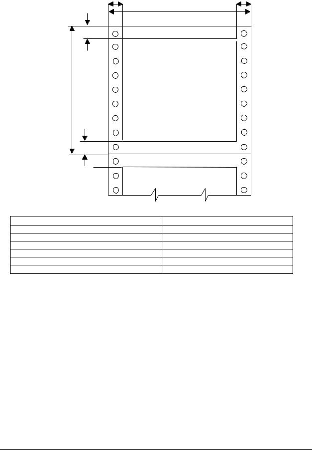
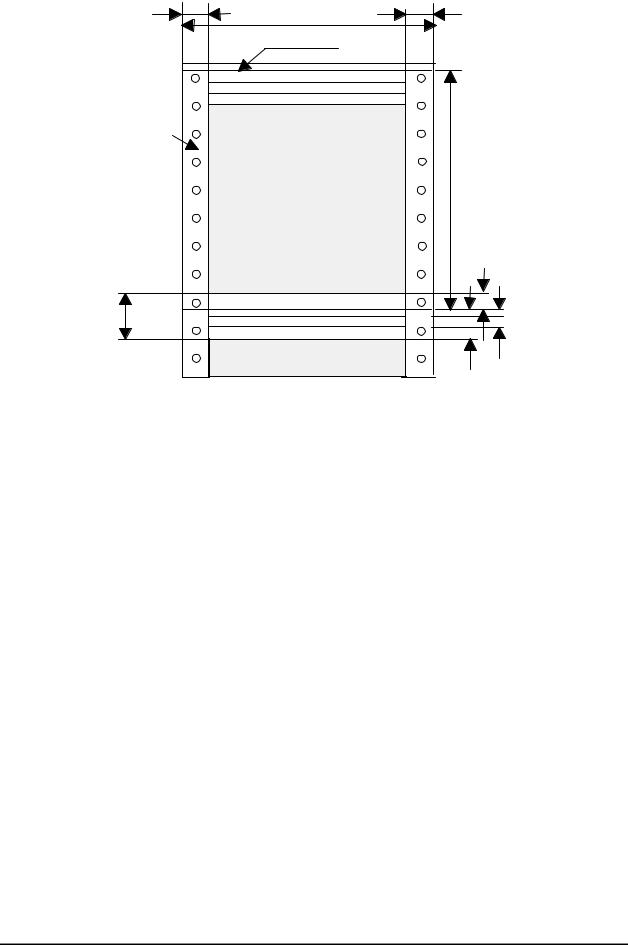
1.2.11 Printable area
‰ Continuous paper : |
Refer to Figure 1-3. |
L M |
R M |
|
P W |
T M |
|
A B C D |
W X Y Z |
P L |
|
A B C D |
W X Y Z |
B M |
|
A B C D |
W X Y Z |
. |
|
|
Continuous Paper |
PW (width) |
Refer to Section 1.2.12. |
PL (length) |
Refer to Section 1.2.12. |
LM (left margin) |
13 mm to 31mm |
RM (right margin) |
13 mm or more |
TM (top margin) |
2.6 mm or more |
BM (bottom margin) |
4.2 mm or more |
Notes 1: In the top 75 mm area, the paper feeding pitch may be irregular.
Notes 2: If the optional pull tractor is used, the top 120 mm area should not be printed. Notes 3: Forms-override printing is available 20 lines after the paper end.
(Paper feeding pitch is not guaranteed.)
The end of the printable area is 9 to 15 mm apart from the bottom edge of the paper.
Figure 1-3. Continuous Paper Printable Area
1-8 |
Rev. B |
|
GENERAL DESCRIPTION
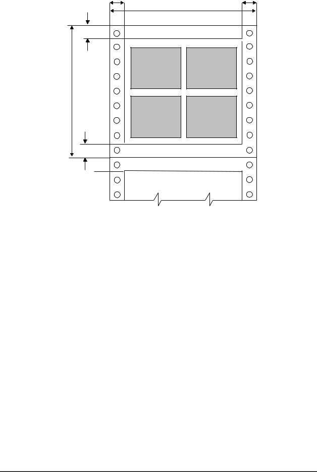
‰ Labels : |
Refer to Figure 1-4. |
L M R M
P W
T M
L a b e l L a b e l
P L
L a b e l |
L a b e l |
B M
|
. |
|
|
|
|
|
|
Continuous Paper |
PW (width) |
|
Refer to Section 1.2.12. |
PL (length) |
|
Refer to Section 1.2.12. |
LM (left margin) |
|
13 mm to 31mm |
RM (right margin) |
|
13 mm or more |
TM (top margin) |
|
2.6 mm or more |
BM (bottom margin) |
|
4.2 mm or more |
Notes 1: Feeding backward or paper (PATH) selection are prohibited. Notes 2: If In the top 75 mm area, the paper feeding pitch may be irregular.
Notes 3: If the optional pull tractor is used, the top 120 mm area should not be printed.. Notes 4: Forms-override printing is available 20 lines after the paper end.
(Paper feeding pitch is not guaranteed.)
The end of the printable area is 9 to 15 mm apart from the bottom edge of the paper.
Figure 1-4. Label Printable Area
Rev. B |
1-9 |
DFX-8500
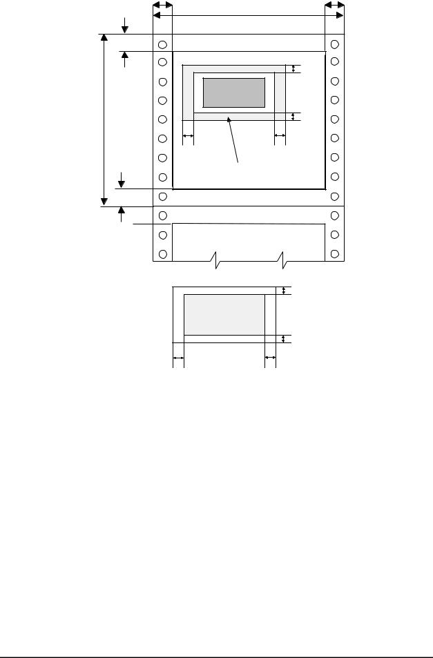
‰ |
Continuous forms with labels : |
Refer to Figure 1-5. |
L M |
R M |
P W |
|
T M |
|
|
T F L |
L a b e l |
|
P L |
B F L |
|
|
L F L |
R F L |
N o n P r in t a b le A r e a |
|
B M |
|
A B C D |
W X Y Z |
|
T O L |
P r in t a b le A r e a |
|
|
B O L |
L O LL a b e l |
R O L |
|
Continuous Paper |
PW (width) |
Refer to Section 1.2.12. |
PL (length) |
Refer to Section 1.2.12. |
LM (left margin) |
13 mm to 31mm |
RM (right margin) |
13 mm or more |
TM (top margin) |
2.6 mm or more |
BM (bottom margin) |
4.2 mm or more |
LFL (left margin from label) |
65 mm or more |
RFL (right margin from label) |
65 mm or more |
TFL (top margin from label) |
12.5 mm or more |
BFL (bottom margin from label) |
12.5 mm or more |
LOL (left margin on label) |
5 mm or more |
ROL (right margin on label) |
5 mm or more |
TOL (top margin on label) |
2 mm or more |
BOL (bottom margin on label) |
2 mm or more |
Notes 1: Feeding backward or paper (PATH) selection are prohibited. Notes 2: If In the top 75 mm area, the paper feeding pitch may be irregular.
Notes 3: If the optional pull tractor is used, the top 120 mm area should not be printed.. Notes 4: Forms-override printing is available 20 lines after the paper end.
(Paper feeding pitch is not guaranteed.)
The end of the printable area is 9 to 15 mm apart from the bottom edge of the paper.
Figure 1-5. Continuous Forms with Labels Printable Area
1-10 |
Rev. B |
|
GENERAL DESCRIPTION
‰ |
Overlapping multi-part forms : |
Refer to Figure 1-6. |
L M |
R M |
|
P W |
|
P e r f o r a t io n s |
C a r r ie r |
|
|
P L |
|
B M |
N A |
|
|
O L |
|
T M |
|
Continuous Paper |
PW (width) |
Refer to Section 1.2.12. |
PL (length) |
Refer to Section 1.2.12. |
LM (left margin) |
19 mm to 31mm |
RM (right margin) |
19 mm or more |
TM (top margin) |
21.2 mm or more |
BM (bottom margin) |
4.2 mm or more |
OL (overlapping length) |
Less than 13.3 mm |
NA (non printable area) |
25.4 mm or more |
Notes 1: Feeding backward or paper (PATH) selection are prohibited. Notes 2: If In the top 75 mm area, the paper feeding pitch may be irregular.
Notes 3: If the optional pull tractor is used, the top 120 mm area should not be printed.. Notes 4: Forms-override printing is available 20 lines after the paper end.
(Paper feeding pitch is not guaranteed.)
The end of the printable area is 9 to 15 mm apart from the bottom edge of the paper.
Figure 1-6. Overlapping Multi-part Form Printable Area
Rev. B |
1-11 |

DFX-8500
1.2.12 Paper and Media
1.2.12.1 Continuous paper (Single sheet and multi-part)
Table 1-5. Continuous Paper
|
|
|
|
Front Entry |
|
Rear Entry |
|||
|
|
|
|
Minimum |
Maximum |
Minimum |
|
Maximum |
|
Width |
(inch) |
|
4.0 |
16.0 |
4.0 |
|
16.0 |
||
|
(mm) |
|
101 |
406 |
101 |
|
406 |
||
Length |
(inch) |
|
4.0 |
17.0 |
4.0 |
|
17.0 |
||
|
(mm) |
|
101 |
431 |
101 |
|
431 |
||
Copies |
|
|
|
1 original + 6 copies |
|
1 original + 5 copies |
|||
Total Thickness |
(inch) |
|
0.0025 |
0.021 |
0.0025 |
|
0.018 |
||
|
(mm) |
|
0.065 |
0.53 |
0.065 |
|
0.46 |
||
Weight |
(g/m2) |
|
52.6 |
82.7 |
52.6 |
|
82.7 |
||
(not multi-part) |
|
(lb) |
|
14 |
22 |
14 |
|
22 |
|
Weight |
(g/m2) |
|
41.4 |
56.4 |
41.4 |
|
56.4 |
||
(one sheet of multi-part) |
|
(lb) |
|
11 |
15 |
11 |
|
15 |
|
Quality |
|
|
Plain paper, Reclaimed paper, Carbonless multi-part forms |
|
|||||
Multi-part binding |
|
|
∙ Rough bindings of multi-part paper cause paper jam. |
|
|||||
|
|
|
∙ The each sheet of multi-part paper should normally be put together by |
||||||
|
|
|
|
spot-gluing, paper-stapling, tape stitching. Spot-gluing is recommended |
|||||
|
|
|
|
for the better printing quality. |
|
|
|
|
|
|
|
|
∙ Spot-gluing must be applied on both sides of paper (Refer to Figure 1- |
||||||
|
|
|
|
7.). |
|
|
|
|
|
|
|
|
∙ The spot-glued parts must be pressed flat. There must be no creases in |
||||||
|
|
|
∙ |
the paper. |
|
|
|
|
|
|
|
|
The paper-stapling must be applied from the front of paper and the |
||||||
|
|
|
∙ |
paper must be flat (Refer to Figure 1-8.). |
|
||||
|
|
|
Paper-stapling must be applied for both feeding directions (Refer to |
||||||
|
|
|
|
Figure 1-9.). |
|
|
|
|
|
|
|
|
∙ The paper-stapling should be flat (Refer to Figure 1-10.). |
||||||
|
|
|
∙ Never use metal staples. |
|
|
|
|
||
|
|
|
∙ The position of binding must be outside of printable area. |
||||||
|
|
|
∙ Multi-part paper should be bound firmly to each other and the binding |
||||||
|
|
|
|
must not be too large. |
|
|
|
|
|
|
|
|
|
|
|
|
|
||
Perforation |
|
|
Refer to Section 1.2.12.5. |
|
|
|
|
||
Notes |
|
|
Refer to Section 1.2.12.6. |
|
|
|
|
||
|
|
|
|
|
|
|
|
|
|
|
|
|
|
|
|
|
|
|
|
Figure 1-7. Dotted Paste Positions
1-12 |
Rev. B |
|
GENERAL DESCRIPTION
Figure 1-8. Paper-stapling Height
Figure 1-9. Paper-stapling Method 1
Figure 1-10. Paper -stapling Method 2
Rev. B |
1-13 |
DFX-8500
1.2.12.2 Labels
Table 1-6. Labels
|
|
Front Entry |
|
Rear Entry |
|||
|
|
Minimum |
|
Maximum |
Minimum |
Maximum |
|
Label Size |
|
Refer to Figure 1-11. |
|
|
|
- |
|
Backing Sheet Width |
(inch) |
4.0 |
|
|
16.0 |
- |
- |
|
(mm) |
101 |
|
|
406 |
|
|
Backing Sheet Length |
(inch) |
3.5 |
|
|
17.0 |
- |
- |
|
(mm) |
89 |
|
|
431 |
|
|
Label Thickness |
(inch) |
0.0 |
|
|
0.0047 |
- |
- |
|
(mm) |
0.0 |
|
|
0.12 |
|
|
Total Thickness |
(inch) |
0.0025 |
|
|
0.0075 |
- |
- |
|
(mm) |
0.065 |
|
|
0.19 |
|
|
Quality |
|
AVERY CONTINUOUS FORM LABELS, |
|
- |
|||
|
|
AVERY MINI-LINE LABELS, or the |
|
|
|||
|
|
same quality labels |
|
|
|
|
|
Perforation |
|
Refer to section 1.2.12.5. |
|
|
|
|
|
Notes |
|
∙ The easy-cone-off label should not be used. |
|
||||
∙Every label must be put on the carrier.
∙Each comer of those labels must be rounded.
∙Each label and backing sheet should not have any folds or creases.
∙Between each label, there should be the same sheet as those labels.
∙The backing sheet must be continuous paper.
∙Labels should be inserted from front entrance.
Refer to Section 1.2.12.6.
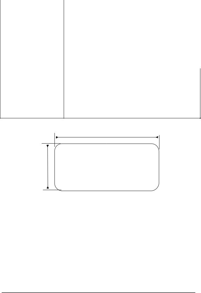
W
H
Width |
|
|
Height |
||
Inch |
|
mm |
Inch |
|
mm |
2.5 |
|
63.5 |
15/16 |
|
23.8 |
4.0 |
|
101 |
15/16 |
|
23.8 |
4.0 |
|
101 |
17/16 |
|
27.0 |
Figure 1-11. Label Size
1-14 |
Rev. B |
|

GENERAL DESCRIPTION
1.2.12.3 Continuous Forms with Labels
Table 1-7. Continuous Forms with Labels
|
|
|
Front Entry |
|
|
Rear Entry |
||||
|
|
|
Minimum |
|
Maximum |
|
Minimum |
|
Maximum |
|
Label Size |
|
Refer to Section 1.2.12.2. |
|
|
|
|
- |
|||
Width |
(inch) |
|
4.0 |
|
|
16.0 |
|
- |
|
- |
|
(mm) |
|
101 |
|
|
406 |
|
|
|
|
Length |
(inch) |
|
4.0 |
|
|
17.0 |
|
- |
|
- |
|
(mm) |
|
101 |
|
|
431 |
|
|
|
|
Weight |
(g/m2) |
|
52.6 |
|
|
82.7 |
|
- |
|
- |
(not multi-part) |
(lb) |
|
14 |
|
|
22 |
|
|
|
|
Weight |
(g/m2) |
|
41.4 |
|
|
56.4 |
|
|
|
|
(one sheet of multi-part) |
(lb) |
|
11 |
|
|
15 |
|
|
|
|
Label Thickness |
(inch) |
|
0.0 |
|
|
0.0047 |
|
|
|
|
|
(mm) |
|
0.0 |
|
|
0.12 |
|
|
|
|
Total Thickness |
(inch) |
|
0.0025 |
|
|
0.021 |
|
- |
|
- |
|
(mm) |
|
0.065 |
|
|
0.53 |
|
|
|
|
Quality (Multi-part forms) |
|
Plain paper, reclaimed paper, carbonless |
|
|
|
|
||||
|
|
multi-part forms |
|
|
|
|
|
|
||
Quality (Label) |
|
AVERY CONTINUOUS FORM LABELS, |
|
|
|
|
||||
|
|
AVERY MNI-LINE LABELS, or the same |
|
|
|
|
||||
|
|
quality labels |
|
|
|
|
|
|
||
Multi-part binding |
|
∙ |
Rough bindings of multi-part paper cause paper jam. |
|
|
|||||
|
|
∙ |
The each sheet of multi-part paper should normally be put |
|||||||
|
|
|
together by spot-gluing, paper-stapling, tape stitching. Spot-gluing |
|||||||
|
|
∙ |
is recommended for the better printing quality. |
|
|
|||||
|
|
Spot-gluing must be applied on both sides of paper (Refer to |
||||||||
|
|
∙ |
Figure 1-7.). |
|
|
|
|
|
|
|
|
|
The spot-glued parts must be pressed flat. There must be no |
||||||||
|
|
|
creases in the paper. |
|
|
|
|
|
|
|
|
|
∙ The paper-stapling must be applied from the front of paper and the |
||||||||
|
|
|
paper must be flat (Refer to Figure 1-8.). |
|
|
|
||||
|
|
∙ Paper-stapling must be applied for both feeding directions (Refer |
||||||||
|
|
|
to Figure 1-9.). |
|
|
|
|
|
|
|
|
|
∙ The paper-stapling should be flat (Refer to Figure 1-10.). |
||||||||
|
|
∙ Never use metal staples. |
|
|
|
|||||
|
|
∙ The position of binding must be outside of printable area. |
||||||||
|
|
∙ |
Multi-part paper should be bound firmly to each other and the |
|||||||
|
|
|
binding must not be too large. |
|
|
|
||||
Perforation |
|
Refer to Section 1.2.12.5. |
|
|
|
|
|
|
||
Notes |
|
∙ |
The easy-cone-off label should not be used. |
|
|
|||||
|
|
∙ Every label must be put on the carrier. |
|
|
|
|||||
|
|
∙ Each comer of those labels must be rounded. |
|
|
||||||
|
|
∙ |
Each label and backing sheet should not have any folds or |
|||||||
|
|
∙ |
creases. |
|
|
|
|
|
|
|
|
|
Between each label, there should be the same sheet as those |
||||||||
|
|
|
labels. |
|
|
|
|
|
|
|
|
|
∙ The backing sheet must be continuous paper. |
|
|
||||||
|
|
∙ |
Continuous forms with labels should be inserted from front |
|||||||
|
|
|
entrance. |
|
|
|
|
|
|
|
|
|
Refer to Section 1.2.12.6. |
|
|
|
|
|
|
||
Rev. B |
1-15 |

DFX-8500
1.2.12.4 Overlapping Multi-part Form
Table 1-8. Overlapping Multi-part Form
|
|
Front Entry |
|
|
Rear Entry |
|||
|
|
Minimum |
|
Maximum |
Minimum |
|
Maximum |
|
Width |
(inch) |
4.0 |
|
16.0 |
- |
|
- |
|
|
(mm) |
101 |
|
406 |
|
|
|
|
Length |
(inch) |
4.0 |
|
17.0 |
- |
|
- |
|
|
(mm) |
101 |
|
431 |
|
|
|
|
Weight |
(g/m2) |
52.6 |
|
82.7 |
- |
|
- |
|
(not multi-part) |
(lb) |
14 |
|
22 |
|
|
|
|
Weight |
(g/m2) |
41.4 |
|
56.4 |
- |
|
- |
|
(one sheet of multi-part) |
(lb) |
11 |
|
15 |
|
|
|
|
Copies |
|
1 original + 5 |
copies + 1 |
backing |
|
- |
||
|
|
sheet |
|
|
|
|
|
|
Total Thickness |
(inch) |
0.0025 |
|
0.021 |
- |
|
- |
|
(print area) |
(mm) |
0.065 |
|
0.53 |
|
|
|
|
Total Thickness |
(inch) |
0.005 |
|
0.028 |
- |
|
- |
|
(overlap area) |
(mm) |
0.13 |
|
0.70 |
|
|
|
|
Overlapping Length |
(inch) |
more than 0 |
|
0.39 |
- |
|
- |
|
|
(mm) |
more than 0 |
|
10 |
|
|
|
|
Quality (multi-part forms) |
|
Plain paper, |
|
reclaimed |
paper, |
|
- |
|
|
|
carbonless multi-part forms |
|
|
|
|
||
Multi-part binding |
|
∙ Multi-part paper must be |
bound at the top side by spot-gluing (Figure 1- |
|||||
|
|
12.). |
|
|
|
|
|
|
|
|
∙ The bindings must not be too hard. And there should not be any spilt |
||||||
|
|
glue. |
|
|
|
|
|
|
|
|
∙ The position of binding must be outside of printable area. |
||||||
|
|
∙ Multi-part paper should be bound firmly to each other and the binding |
||||||
|
|
must not be too large. |
|
|
|
|
||
Perforation |
|
Refer to Section 1.2.12.5. |
|
|
|
|
||
Notes |
|
∙ Overlapping multi-part form should be inserted from front entrance. |
||||||
|
|
Refer to Section 1.2.12.6. |
|
|
|
|
||
1.2.12.5 Perforation
∙Weak horizontal and vertical perforations cause paper jams.D
∙The length ratio of the cut part and uncut part of perforations must be more than 3 to 1 and less than 5 to 1 (Refer to Figure 1-13.).
∙Horizontal perforations must have an uncut part in each end of the paper (Refer to Figure 1-14.).
∙At the intersection of horizontal and vertical perforations, the cut part of the perforations must not cross each other (Refer to Figure 1-15.).
∙The raised part at the perforation must be less than 1 mm when the bottom layer kept by force (Refer to Figure 1-16.).
1.2.12.6 Notes
∙Clean paper (with no folds, creases, tears) should be used (Refer to Figure 1-17.).
∙The sprocket hole must be circular. The hole may have teeth (Refer to Figure 1-18.).
∙The sprocket hole of each layer must not be shifted (Refer to Figure 1-19.).
∙The litter of sprocket holes must be removed from the paper.
∙Paper should be fan-folded at horizontal perforations. Never use one that is not fan-folded property (Refer to Figure 1-20.).
∙No hole is acceptable in the printable area.
∙Paper must be torn off accurately along perforations.
1-16 |
Rev. B |
|

GENERAL DESCRIPTION
P a g e L e n g t h
1 9 - 3 1
1 3 + 3
1 9 |
o r e |
m o r e |
o r |
||
|
m |
|
1 3 |
+ |
3 |
|
o r |
|
|
2 1 . 2 |
|
M u lt i - p a r t c u t s h e e t
B a s e s h e e t
S p o t - g lu e d p a r t
m o r e |
o r e |
P e r f o r a t io n o f b a s e s h e e t |
|
o r |
m |
r |
|
|
o |
2 1 . 2 |
4 . 2 |
S p o t - g lu e d p s r t
L o w e r e d g e
P a g e W id t h |
S p o t - g lu e d p a r t |
|
|
|
U n it : m m |
Figure 1-12. Paper Width Overlapping Area
|
|
|
|
|
|
Figure 1-13. Perforations 1 |
|
Figure 1-14. Perforations 2 |
Rev. B |
1-17 |

DFX-8500
Figure 1-16. Raised Portion at a Perforation
a) |
b) |
c) |
|
|
Figure 1-15. Perforations 3 |
|
|
|
|
|
|
|
|
|
|
Figure 1-18. Sprocket Hole 1
Figure 1-19. Sprocket Hole 2
Figure 1-17. Unsuitable Paper
Figure 1-20. Bad Folded Paper
1-18 |
Rev. B |
|
GENERAL DESCRIPTION
1.3 INTERFACES
The DFX-8500 is equipped with parallel interface, serial interface, and optional Type-B interface card. This section presents the specifications for each interface type.
1.3.1 Parallel Interface (Forward channel)
‰ |
Data transmission mode: |
8-bit parallel, IEEE-1284 compatibility mode |
‰ |
Synchronization: |
/STROBE pulse |
‰ |
Connector type: |
57-30360 (AMPHENOL) 36-pin plug or equivalent |
‰ |
Handshaking: |
BUSY and /ACK handshaking |
Notes 1: BUSY signal is set high before setting either /ERROR low or PE high and held high until all these signals return to their inactive state. BUSY signal is at a high level in the following cases.
„During data entry (see data transmission timing) „When input data buffer is full.
„During /INIT signal is at a low level or during hardware initialization „During printer error (see /ERROR signal)
„During test printing or during setting printing „During SelecType
„When the parallel interface is not selected.
Notes 2: /ERROR signal is at a low level when the printer is in one of the following states. „Printer hardware error (fatal error)
„Paper out error „Paper jam error „Cover open status
„Incomplete paper change „Paper size error „Ribbon jam error
Notes 3: PE signal is at a high level during paper out error.
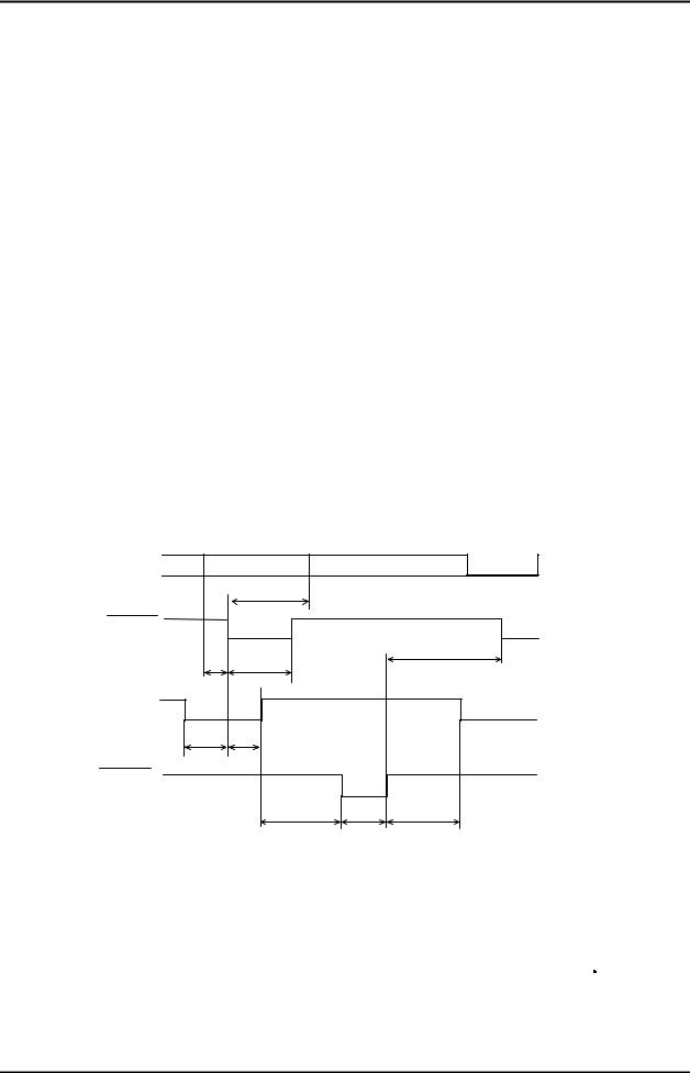
‰ Data transmission timing: |
Refer to Figure 1-21. |
|
|
D A T A |
( n ) |
D A T A |
( n + 1 ) |
|
|
|
|
|
|||
D A T A |
|
|
|
|
|
|
|
|
t |
h o ld |
|
|
|
S T R O B E |
|
|
|
|
||
|
|
t |
s t b |
t n e x t |
|
|
t |
|
|
|
|||
s e t u p |
|
|
|
|
||
B U S Y |
|
|
|
|
|
|
|
t |
r e a d y |
|
|
|
|
A C K N L G |
t b u s y |
|
|
|||
|
|
|
|
|
||
|
|
|
t r e p ly |
t a c k t n b u s y |
||
Parameter |
Minimum |
Maximum |
Parameter |
Minimum |
Maximum |
|
|
|
|
|
|
t setup |
500 ns |
--- |
t ack |
500 ns |
10 us |
t hold |
500 ns |
--- |
t nbusy |
0 |
--- |
t stb |
500 ns |
--- |
t next |
0 |
--- |
t ready |
0 |
--- |
tt-out* |
--- |
120 ns |
t busy |
--- |
500 ns |
tt-in** |
--- |
200 ns |
t reply |
--- |
--- |
|
|
|
Note: * Rise and fall time of output signals ** Rise and fall time of input signals.
Figure 1-21. Data Transmission Timing
Rev. B |
1-19 |

DFX-8500 |
|
|
|
|
|
‰ Signal Level: |
TTL-level compatible, IEEE-1284 level 1 device |
||||
|
|
Refer to Table 1-9. |
|
||
|
|
|
Table 1-9. Signal Level |
|
|
|
Parameter |
Minimum |
|
Maximum |
Condition |
|
VOH* |
- |
|
5.5 V |
|
|
VOL* |
-0.5 V |
|
- |
|
|
IOH* |
- |
|
0.32 mA |
VOH = 2.4 V |
|
IOL* |
- |
|
12 mA |
VOL = 0.4 V |
|
CO |
- |
|
50 pF |
|
|
VIH |
- |
|
2.0 V |
|
|
VIL |
0.8 V |
|
- |
|
|
IIH |
- |
|
0.32 mA |
VIH = 2.4 V |
|
IIL |
- |
|
12 mA |
VIL = 0.8 V |
|
CI |
- |
|
50 pF |
|
Note: * A low logic level on the logical high signal is 2.0 V or less when the printer is powered off. And this signal is equal or exceeding 3. 0 V when the printer is powered on. The receiver shall provide an impedance equivalent to 7.5 K ohms to ground.
‰Connector pin assignments and signals: Refer to Table 1-10.
Table 1-10. Signal and Connector Pin Assignment (Forward channel)
Pin No. |
Signal Name |
Return GND pin |
In/Out* |
Functional Description |
1 |
/STROBE |
19 |
In |
The strobe pulse. Read-in of data is performed |
|
|
|
|
at the falling edge of this pulse. |
2-9 |
DATA 0-7 |
20-27 |
In |
The DATA0 through DATA7 signals represent |
|
|
|
|
data bits 0 to 7, respectively. Each signal is at |
|
|
|
|
high level when data is logical 1 and low level |
|
|
|
|
when data is logical 0. |
10 |
/ACKNLG |
28 |
Out |
This signal is a negative pulse indicating that |
|
|
|
|
the printer can again accept data. |
11 |
BUSY |
29 |
Out |
A high signal indicates that the printer cannot |
|
|
|
|
receive data. |
12 |
PE |
28 |
Out |
A high signal indicates paper-out error. |
13 |
SLCT |
28 |
Out |
Always at high level when the printer is |
|
|
|
|
powered on. |
14 |
/AFXT |
30 |
In |
Not used. |
31 |
/INIT |
30 |
In |
The falling edge of a negative pulse or a low |
|
|
|
|
signal on this line causes the printer to initialize. |
|
|
|
|
Minimum 50 us pulse is necessary. |
32 |
/ERROR |
29 |
Out |
A low signal indicates printer error condition. |
36 |
/SLIN |
30 |
In |
Not used. |
18 |
Logic H |
- |
Out |
Pulled up to +5V via 3.9K ohm resistor. |
35 |
+5V |
- |
Out |
Pulled up to +5V via 3.3K ohm resistor. |
17 |
Chassis GND |
- |
- |
Chassis GND. |
16,33,19,30 |
GND |
- |
- |
Signal GND. |
15,34 |
NC |
- |
- |
Not connected. |
Note: * In/Out refers to the direction of signal flow from the printer’s point of view.
1-20 |
Rev. B |
|

|
|
|
GENERAL DESCRIPTION |
1.3.2 Parallel Interface (Reverse channel) |
|||
‰ |
Data transmission mode: |
IEEE-1284 nibble mode |
|
‰ |
Connector type: |
57-30360 (AMPHENOL) 36-pin plug or equivalent |
|
‰ |
Synchronization: |
No Info. |
|
‰ |
Handshaking: |
No info. |
|
‰ |
Data transmission timing: |
No info. |
|
‰ |
Signal Level: |
TTL-level compatible, IEEE-1284 level 1 device |
|
‰ |
Extensibility request : |
The printer responds to the extensibility request in the affirmative, |
|
|
|
when the request is 00h or 04h, which mean: |
|
|
|
00h : Request nibble mode of reverse channel transfer |
|
|
Device ID : |
04h : Request device ID in nibble mode of reverse channel transfer |
|
‰ |
|
|
|
|
|
[00h][3Ah] |
|
|
|
MPG:EPSON; |
|
|
|
CMD:ESCP9,PRPII9,BDC; |
|
|
|
MDL:DFX-8500; |
|
|
|
CLS:PRINTER; |
|
‰Connector pin assignments: Refer to Table 1-11.
Table 1-11. Signal and Connector Pin Assignment (Reverse channel)
Pin No. |
Signal Name |
I/O* |
Description |
1 |
/STROBE |
IN |
HostCIk: This signal is a strobe pulse used to read extension |
|
|
|
request values from the host computer during negotiation. |
2-9 |
DATA 1-8 |
IN |
The signals are data bits of extension request Values during |
|
|
|
negotiation. This printer supports following values: |
|
|
|
0000 0100: Request Device ID (by nibble mode sending) |
|
|
|
0000 0000: Request nibble mode |
10 |
/ACKNLG |
OUT |
PtrCIk: Printer data sending clock. |
11 |
BUSY |
OUT |
PtrBusy: Printer sending data bits 3 and 7 during data transfer to |
|
|
|
the host computer |
12 |
PE |
OUT |
AckDataReq: Printer sending data bits 2 and 6 during data transfer |
|
|
|
to the host computer |
13 |
SLCT |
OUT |
Xflag: Printer sending data bits 2 and 6 during data transfer to the |
|
|
|
host computer. |
14 |
/AUTO-FEED |
IN |
HostBusy: This signal informs the printer of the host computer |
|
|
|
state. When the signal is HIGH, the host computer cannot accept |
|
|
|
data. |
15 |
NC |
- |
Not used. |
16 |
GND |
- |
Logic ground level |
17 |
CHASSISGND |
- |
Connected to the printer chassis. The printer chassis GND and the |
|
|
|
signal GND are connected to each other. |
18 |
NC |
- |
Not connected. |
19-30 |
GND |
- |
Ground level for the twisted pair return signal. |
31 |
/INIT |
IN |
nlnit: High level fixed |
32 |
/ERROR |
OUT |
nDataAvaiI: Printer sending data bits 0 and 4 during data transfer to |
|
|
|
the host computer. |
33 |
GND |
- |
Same as for ins19to30. |
34 |
NC |
- |
Not used. |
35 |
+5 |
- |
Pulled up to +5V through 1.0K ohm resistor. |
36 |
/SLCT IN |
IN |
1284Active: If this signal is set to HIGH, this printer active |
|
|
|
P1284(reverse mode). |
Note: * In/Out refers to the direction of signal flow from the printer’s point of view.
Rev. B |
1-21 |

DFX-8500
1.3.3 |
|
Serial Interface |
|
‰ |
Synchronization : |
Asynchronous |
|
‰ |
Signal level (ELA-232D) : |
|
|
„ |
MARK (logical 1) : |
-3Vto-25V |
|
„ |
SPACE (logical 0) : |
+3Vto+25V |
|
‰ |
Word length : |
|
|
„ |
Start bit : |
1 bit |
|
„ |
Data bit : |
8 bit |
|
„ |
Parity bit : |
Odd, Even, Non, of Ignore |
|
„ |
Stop bit : |
1 bit or more |
|
‰ |
Baud rate : |
2400, 4800, 9600 or 19200 bps |
|
‰ |
Handshaking : |
DTR signal or X-ON / X-OFF |
|
„ |
DTR=MARK, X-OFF : |
Indicates that the printer cannot receive data. |
|
„ |
DTR=SPACE, X-ON : |
Indicates that the printer is ready to receive data. |
|
Note: |
The DTR signal is MARK and X-OFF code (DC3, 13h) is transmitted when the rest of the |
||
|
input buffer becomes 256-byte. The DTR signal is SPACE and X-ON code (DC1, 11h) is |
||
|
transmitted when the rest of the input buffer is regained 256-byte. |
||
‰ |
Error handling : |
When parity error is detected, the received byte is changed to the |
|
|
|
|
"*" character code. Overrun error and framing error are ignored. |
‰ |
Connector : |
25 pin sub-miniature D-shell connector (female) |
|
‰ |
Connector pin assignment and signals : Refer to Table 1-12. |
||
Table 1-12. Signal and Connector Pin Assignment (EIA-232D)
Pin No. |
Signal Name |
In / Out* |
Functional Description |
2 |
TXD |
Out |
Transmit data. |
20 |
DTR |
Out |
Indicates that the printer is ready to receive data or not. |
11 |
REV |
Out |
Connected directly to the DTR signal. |
4 |
RTS |
Out |
Request to send. always SPACE level when the printer is |
|
|
|
powered on. Pulled up to +12 V via 4.7K-ohm resistor. |
3 |
RXD |
In |
Receive data |
7 |
Signal GND |
- |
Signal GND |
1 |
Chassis |
- |
Chassis GND |
|
GND |
|
|
Other |
NC |
- |
Not used. Not connected. |
Note: * In/Out refers to the direction of signal flow from the printer’s point of view.
1.3.4 Optional Interface
Type-B and Type-B level 2 optional interfaces are available (Refer to Table 1-1.).
1-22 |
Rev. B |
|
 Loading...