


 Loading...
SHERWOOD INDUSTRIES IS AN ENVIRONMENTALLY RESPONSIBLE COMPANY
THIS MANUAL IS PRINTED ON RECYCLED PAPER
EG 28 Direct Vent
B y S H E R W O O D I N D U S T R I E S
O W N E R S M A N U A L
WHAT TO DO IF YOU SMELL GAS
•Open windows
•Do not try to light any appliance.
•Do not touch any electrical switch; do not use any phone in your building.
•Immediately call your gas supplier from a neighbor's phone. Follow the gas supplier's instructions.
•If you cannot reach your gas supplier, call the fire department.
WARNING
If the information in this manual is not followed exactly, a fire or explosion may result causing property damage, personal injury or loss of life. Installation and service must be performed by a qualified installer, service agency or the gas supplier.
FOR YOUR SAFETY
Do not store or use gasoline or other Flammable vapors and liquids in the vicinity of this or any other appliance.
SAFETY PRECAUTIONS
FOR SAFE INSTALLATION AND OPERATION OF YOUR "ENVIROGAS" STOVE, PLEASE,
CAREFULLY READ THE FOLLOWING INFORMATION:
GENERAL
•Installation and repair should be done by a qualified service person. The appliance should be inspected before use and at least annually by a qualified service person. More frequent cleaning may be required due to excessive lint from carpeting, bedding material, etc. It is imperative that control compartments, burners and circulating air passageways of the appliance be kept clean.
•Due to high temperatures the appliance should be located out of high traffic areas and away from furniture and draperies.
Children and adults should be alerted to hazards of high surface temperatures and should stay away to avoid burns or clothing ignition.
•Young children should be carefully supervised when they are in the same room as the appliance.
•Clothing or other flammable material should not be placed on or near the appliance.
•All "ENVIROGAS" gas-fired appliances must be installed in accordance with these instructions. Carefully read all the instructions in this manual first. Consult the building authority having jurisdiction to determine the need for a permit prior to commencing the installation.
•NOTE Failure to follow these instructions could cause a malfunction of the fireplace, which could result in death, serious bodily injury, and/or property damage.
•Failure to follow these instructions may also void your fire insurance and/or warranty.
FOR YOUR SAFETY:
•Installation and service must be performed by a qualified installer, service agency or the gas supplier.
•Installation must conform to local codes or, in the absence of local codes with the current CAN 1-B 149 installation code in Canada or the current National Fuel Gas Code ANSI Z223.1 in the USA.
•To prevent injuries do not allow anyone who is unfamiliar with the operation to use the stove.
•Always keep the appliance area clear and free of combustible materials, gasoline and other flammable vapors and liquids.
•These appliances should not be used as a drying rack for clothing or for hanging Christmas stockings or decorations.
•Due to the paint curing on the stove a faint odor and slight smoking will likely be noticed when the stove is first used. Open a window until the slight smoking stops. Always connect this gas stove to a chimney and vent to the outside of the building envelope. Never vent to another room or inside a building. Make sure you use the vent pipe that is specified. Make sure that the vent is properly sized and is of adequate height to provide the proper draft. Inspect the venting system annually for blockage and any signs of deterioration.
WARNING: Do not operate with cracked or broken glass. Under no circumstances should this appliance be modified. Parts that have to be removed for servicing must be replaced prior to operating this appliance. Only parts supplied by Envirogas should be used in this appliance and replacement should only be performed by a licensed or qualified service person.
•Never use solid fuels such as wood, paper, cardboard, coal, or any other flammable liquids etc., in this appliance.
•Do not use this heater if any part has been under water. Immediately call a qualified service technician to inspect the heater and to replace any part of the control system and any gas control, which has been under water.
•Do not abuse glass by striking or slamming door shut.
2
TABLE OF CONTENTS
Safety Precautions |
2 |
Code Approvals |
3 |
Deciding where to locate your stove |
4 |
Planning your installation |
6 |
Installation of Log Sets and Embers |
14 |
Operating Instructions |
15 |
Maintenance and Technical |
16 |
Trouble Shooting |
17 |
Gas Line Connection |
18 |
Electrical |
19 |
Parts and Accessories |
20 |
Fuel Conversion |
21 |
Warranty |
22 |
Parts List |
23 |
Exploded Views |
24-25 |
Installation Data Sheet |
26 |
Mobile Home Information |
3,13,19,21 |
CODE APPROVALS
• This Direct Vent appliance draws all of its combustion air from outside of the dwelling through specially designed vent pipe.
These appliances have been tested by INTERTEK TESTING SERVICES (WH) and found to comply with the established standards for a DIRECT VENT GAS FIREPLACE in CANADA and the USA as follows:
LISTED GAS FIRED GRAVITY DIRECT VENT WALL FURNACE (EG 28 DV. Nat. & LPG. )
TESTED TO: ANSI Z21.88-1998 CSA 2.33-M98 VENTED GAS FIREPLACE HEATER. UL307B-1995 GAS BURNING HEATING APPLIANCES FOR MANUFACTURED HOMES. CGA 2.17-M91 GAS FIRED APPLIANCES FOR USE AT HIGH ALTITUDE
SPECS:
ENVIROGAS EG 28 DIRECT VENT UNITS;
•have all been certified for use with either natural or propane gases. (see control panel and rating label.)
•are not for use with solid fuels.
•must not be connected to a chimney flue serving a separate solid-fuel burning appliance.
•are approved for bedroom or bedsitting room.
(IN CANADA: must be installed with a listed wall thermostat) (IN USA: see current ANSI Z223.1 for installation instructions.)
•must be installed in accordance with local codes if any. If none exist use current installation code CAN/CGA b149 in Canada or ANSI Z223.1 / NFPA 54 in the USA.
•must be properly connected to an approved venting system.
•Manufactured (mobile) home installation must be in accordance with the Manufactured Home Construction and Safety Standard, UL 307B, Title 24 CFR, Part 3280 and/or The Standard for Manufactured Home Installations, ANSI A225.1/NFPA 501A. The unit must be bolted to the floor of the mobile home and must be electrically grounded to the steel chassis.
•are approved for installation on combustible materials.
•are not approved for closet or recessed installations.
ASSEMBLY INSTRUCTIONS
PREPARATION FOR INSTALLATION
•Remove the packaging from the appliance, and check to make sure there is no damage. If damage is found, please report it to both the carrier and your dealer as soon as possible.
•Before beginning, carefully check the glass door and the log set
3
DECIDING WHERE TO LOCATE YOUR STOVE
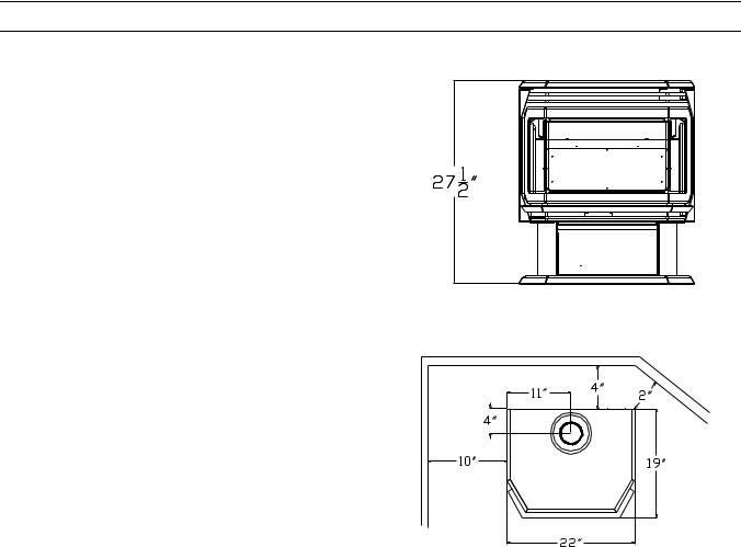
DIMENSIONS:
Front Width: |
22"/ 56 cm |
|
Rear Width: |
22"/ 56 cm |
|
Height: |
27-1/2"/ 70 cm* |
|
Depth |
|
19"/ 48 cm |
(*not including vent coupling) Shipping Weight: 210 lbs/95 kg
FIG. 1
CLEARANCES:
A. Side wall to stove |
10"/ |
25 cm |
B. Rear wall to stove |
4"/ |
10 cm |
C. Combustible to stove Top |
22”/ 56 cm |
|
D. Floor to stove |
0"/ |
0 cm |
E. Corner clearance |
2"/ |
5 cm |
F. Alcove depth |
48"/ |
122 cm |
Maintain sufficient clearances for service and maintenance
FIG. 2
•The stove should be located out of traffic and away from furniture and draperies.
•The stove should have sufficient access for its safe operation and maintenance.
•Locate a position where the flue system of the stove can be properly installed without damaging the integrity of the building. e.g. cutting a wall or ceiling joist.
•The stove can be installed on any standard flooring materials i.e. Wood, carpet or linoleum.
•Check stove and flue system clearance requirements.
•Locate the stove where it can be accessed by a gas supply line.
•Locate the stove in a large and open room that is centrally located in the house. This will optimize heat circulation and comfort.
•As the stove is equipped with a convection fan, ensure that an electrical outlet is within 6ft. (1.8m) of the stove.
•These stoves can be installed in bedrooms.
(IN CANADA: must be installed with a listed wall thermostat) (IN USA: see current ANSI Z223.1 for installation instructions.)
•The flow of combustion and ventilation air must not be obstructed.
4

VENT TERMINAL CLEARANCES
A= Clearance above grade, verandah, porch, deck, or balcony [*12 inches (30 cm) minimum]
B= Clearance to window or door that may be opened [*12 inches (30 cm) minimum]
C= Clearance to permanently closed window
[minimum 12 inches (30 cm) recommended to prevent condensation on window]
D= Vertical clearance to ventilated soffit located above the terminal within a horizontal distance of 2 feet (60 cm) from the center-line of the terminal (24 inches (60 cm) minimum)
E= Clearance to unventilated soffit [18 inches (45 cm) minimum]
F= Clearance to outside corner [12 inches minimum] G= Clearance to inside corner [`12 inches minimum]
H= *Not to be installed above a meter/regulator assembly within 3 feet (90 cm) horizontally from the center-line of the regulator
I= Clearance to service regulator vent outlet [*6 feet (1.8m) minimum]
J= Clearance to non-mechanical air supply inlet to building or the combustion air inlet to any other appliance
[12 inches (30 cm) minimum]
K= Clearance to a mechanical air supply inlet [*6 feet (1.8m) minimum]
L=*** Clearance above paved side-walk or paved driveway located on public property
[*7 feet (2.1m) minimum]
M= Clearance under verandah, porch, deck, or balcony [*24 inches (60 cm) minimum **]
***A vent shall not terminate directly above a sidewalk or paved driveway, which is located between two single family dwellings and serves both dwelling
**Only permitted if verandah. Porch, deck, or balcony is fully open on a minimum of 2 sides beneath the floor
As specified in CGA B149 Installation Codes (1991) Note: Local Codes or Regulation
Installations over 15 feet (4.5m) vertical require the use of a vent restrictor
WHEN VENTING THIS APPLIANCE YOU MUST STAY WITHIN THE SHADED AREA (see venting chart provided) FOR ALL VENTING APPLICATIONS.
VENT RESTRICTOR RING: A vent restrictor ring is supplied with each direct vent fireplace. This restrictor ring is to be installed when the vertical chimney installation is over 15’ (4.57 M). Before the chimney is placed onto the stove, place this vent restrictor ring into the 4” (10.16 CM) flue pipe(as shown), once the vent restrictor ring has been installed, the vertical sections of chimney can be installed.
5
These models have been tested and certified for use with SIMPSON DURAVENT DIRECT VENT TYPE "GS" PIPE FOR GAS STOVES. SECURITY VENTING SYSTEMS (SECURE VENT) Kits are available for vertical venting or horizontal venting. It is recommended that a bead of RTV High Temperature Silicone be applied to each outer vent joint and milpac to each inner joint before installation.
This model has also been tested for horizontal venting installations when using SHERWOOD INDUSTRIES LTD. horizontal venting kit PART # EG 40-500
SHERWOOD INDUSTRIES LTD PARTS: |
|
|
|
1 |
Horizontal direct vent termination cap |
4 |
Spring spacers |
1 |
Flue collar adapter 5” tall (4 T20 Torx) |
3 |
Decorative brass rings |
1 |
Wall thimble |
1 |
4oz tube RTV silicone |
1 |
Inside finish trim collar |
1 |
4oz can charcoal gray spray paint |
1 |
5’ length of 4” double walled flex pipe |
20 |
9/16” tech screw |
2 |
24” sections 6 5/8’ straight pipe |
8 |
1 1/2” wood screws |
1 |
6 5/8” 90° elbow |
1 |
Vinyl siding deflector |
A MINIMUM VERTICAL LENGTH OF 24" TO THE FIRST 90 DEGREE ELBOW IS REQUIRED. WITH THIS MINIMUM VERTICAL RISE, HORIZONTAL RUNS OF FROM ONE TO FOUR FEET ARE PERMITTED TO REACH THE OUTSIDE VENT TERMINATION.
BEFORE BEGINNING THE INSTALLATION TAKE CARE TO ENSURE AN APPROPRIATE OUTSIDE LOCATION FOR THE VENT TERMINATION CAN BE ACCOMMODATED. FOLLOW THE VENT LENGTH DIAGRAM PRECISELY.
VENTING TERMINALS CANNOT BE RECESSED INTO A WALL OR SIDING.
If extra elbows are being used, overall allowable length will be reduced by 3 ft. per additional elbow
Simpson Duravent Parts
Number |
Description |
Number |
Description |
908B |
6" Pipe Length, Black |
943S |
Flashing, 7/12 to 12/12 Roof Pitch |
907B |
9" Pipe Length, Black |
953 |
Storm Collar |
906 (B) |
12" Pipe Length, (Black) |
963 |
Ceiling Firestop |
904 (B) |
24" Pipe Length, (Black) |
988 |
Wall Strap |
903 (B) |
36" Pipe Length, (Black) |
984 |
Horizontal Square Termination |
902 (B) |
48" Pipe Length, (Black) |
985 |
High Wind Horizontal Termination |
911 (B) |
11" to 14-5/8" Pipe , Adjustable, Black |
980 |
Vertical Termination |
945 (B) |
45° Elbow, (Black) |
991 |
High Wind Vertical Termination |
990 (B) |
90° Elbow, (Black) |
950 |
Vinyl Siding Standoff |
940 |
Round Support / Wall Thimble Cover |
942 |
Wall Thimble |
941 |
Cathedral Ceiling Support Box |
971 |
Horizontal Termination Kit A |
943 |
Flashing, 0/12 to 6/12 Roof Pitch |
|
|
Add suffix (B) for optional black parts as listed.
PLANNING YOUR INSTALLATION
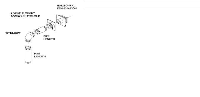
There are two basic types of Direct Vent System installations. The two types of installations are:
Vertical Termination Horizontal Termination
6
When planning your installation, it will be necessary to select the proper length of vent pipe for your particular requirements. It is important to note when passing through a wall, the maximum allowable wall thickness is 10-inches (254mm), 1 ½ inches clearance to combustibles must be maintained. Select the amount of vertical rise desired for “vertical-to-horizontal” type installations. To determine the length of vent pipe required for vertical installations, measure the distance from the appliance flue outlet to the ceiling, the ceiling thickness, the vertical rise through the attic or second story, and allow for sufficient vent height above the roofline. For two story applications, A firestop is required at each floor level. If an offset is needed in the attic, additional pipe and elbows will be required. To connect the venting system to the appliance flue outlet, a twist-lock adapter is built into the appliance at the factory.
HORIZONTAL INSTALLATION
STEP 1. Set the appliance in the desired location. Check to determine if wall studs or roof rafters are in the way when the venting system is attached. If this is the case, you may want to adjust the location of the appliance.
STEP 2. Direct vent pipe and fittings are designed with special twist-lock connections. Assemble the desired combination of black pipe and elbows to the appliance adapter with pipe seams oriented towards the wall or floor, as much out of view as possible.
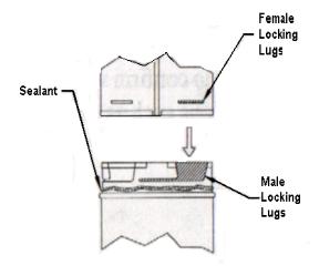
Place a bead of Mil-Pac on the outer edge of the inner exhaust pipe (non-flared end). Place a bead of high temperature silicone on the male edge of the outer pipe. Push the pipe sections completely together, then twist-lock one section clockwise approximately one-quarter turn, until the two sections are fully locked. The female locking lugs will not be visible from the outside, on black pipe. They may be located by examining the inside of the female ends as shown in FIG-10.
NOTE:
(1)Twist-lock procedure: four indentations, located on the female end of the pipes and fittings, are designed to slide straight onto the male ends of adjacent pipes and fittings, by orienting the four pipe indentations so they match and slide into the four entry slots on the male end.
(2)Horizontal runs of vent pipe must be supported every three feet. Wall straps are available for this purpose.
FIG.10
STEP 3. With the pipe attached to the stove into the correct location, mark the wall for a 10 inch x 10 inch square hole. The center of the square hole should match the centerline of the horizontal pipe. Cut and frame the 10-inch x 10-inch hole in the exterior wall where the vent will be terminated. If the wall being penetrated is constructed of noncombustible material i.e. masonry or concrete, a 7-inch hole is acceptable.
STEP 4. Position the horizontal vent termination in the center of the 10-inch square hole, and attach to the exterior wall with the four screws provided. Before attaching the Vent Termination to the exterior wall, run a bead of non-hardening mastic around the edges, so as to make a seal between the termination and the wall. The arrow on the vent termination should be pointing up, insure that the proper clearances to combustible materials are maintained.
STEP 5. Before connecting the horizontal run of the vent pipe to the vent termination, slide the black decorative wall thimble cover over the vent pipe.
STEP 6. Slide the appliance and vent assembly towards the wall, carefully inserting the vent pipe into the cap assembly. It is important that the vent pipe extend into the vent cap a sufficient distance with a minimum of 1 ¼inch overlap. Secure the connection between the vent cap pipe and the vent cap by attaching the two sheet metal straps extending from the vent cap assembly into the outer wall of the vent pipe. Use the two sheet metal screws provided to connect the straps to the vent pipe. Bend any remaining portion of the sheet metal straps back towards the vent cap, so the decorative wall thimble FIG-13 will conceal it.
7
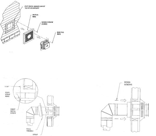
STEP 7. Slide the decorative wall thimble up to the wall surface and attach with the screws provided. Apply decorative brass or chrome trim if desired. FIG-14.
FIG. 11 |
FIG. 12 |
FIG-13 |
FIG-14 |
NOTES: (1) The four wood screws provided should be replaced with the appropriate fasteners for stucco, brick, concrete, or other types of siding.
(2) For buildings with vinyl siding, a vinyl siding standoff (950), should be installed between the vent cap and the exterior wall FIG-12. Attach the vinyl siding standoff to the horizontal termination. The vinyl siding standoff prevents excessive heat from possibly melting the vinyl siding material. Note that the horizontal vent termination bolts onto the flat portion of the vinyl siding standoff. (shaded area in FIG-12), so that an air space will exist between the wall and the vent termination.
NOTES: (1) The horizontal run of vent pipe must be level and should have a ¼ inch rise for every one foot of run towards the termination. Never allow the vent to run downward. This could cause high temperature and may present the possibility of a fire
(2)The location of the horizontal vent termination on the exterior wall must not be easily blocked or obstructed. Termination clearances are as follows:
(3)When installing a vent pipe in chase the minimum clearance to combustibles is 4” inches (100 mm).
8
Loading...