


OPERATING INSTRUCTIONS AND OWNER’S MANUAL
MR. HEATER
OM |
MHU 45 |
LED |
MHU 75 |
READ INSTRUCTIONS CAREFULLY: Read and follow all instructions. Place instructions in a safe place for future reference. Do not allow anyone who has not read these instructions to assemble, light, adjust or operate the heater.
HEATSTAR
M |
HSU 45 |
LEDO |
HSU 75 |
COMPACT UNIT HEATER
WARNING: Improper installation, adjustment, alteration, service or maintenance can cause injury or property damage. Refer to this manual. For assistance or additional information consult a qualified installer, service agency or the gas supplier.
—WHAT TO DO IF YOU SMELL GAS
•Open Windows
• DO NOT try to light any appliance.
•DO NOT use electrical switches.
•DO NOT use any telephone in your house. Immediately call your local gas supplier from a neighbor’s telephone. Follow the gas supplier’s instructions.
•Do not touch any electrical switch; do not use any phone in your building.
•Installation and service must be performed by a qualified installer, service agency or the gas supplier.
•If you cannot reach your gas supplier, call the Fire Department.
FOR YOUR SAFETY:
Do not store or use gasoline or other flammable vapors and liquids in the vicinity of this or any other appliance.
WARNING: If the information in these instructions are not followed exactly, a fire or explosion may result causing property damage, personal injury or loss of life.
ENERCO GROUP, INC., 4560 W. 160TH ST., CLEVELAND, OHIO 44135 • 216-916-3000 |
03/05 Revision L1 #60016 |
WARNING:
 YOUR SAFETY IS IMPORTANT TO YOU AND TO OTHERS, SO PLEASE READ THESE INSTRUCTIONS BEFORE YOU OPERATE THIS HEATER.
GENERAL HAZARD WARNING:
 FAILURE TO COMPLY WITH THE PRECAUTIONS AND INSTRUCTIONS PROVIDED WITH THIS HEATER, CAN RESULT IN DEATH, SERIOUS BODILY INJURY AND PROPERTY LOSS OR DAMAGE FROM HAZARDS OF FIRE, EXPLOSION, BURN, ASPHYXIATION, CARBON MONOXIDE POISONING, AND/OR ELECTRICAL SHOCK.
 ONLY PERSONS WHO CAN UNDERSTAND AND FOLLOW THE INSTRUCTIONS SHOULD USE OR SERVICE THIS HEATER.
 IF YOU NEED ASSISTANCE OR HEATER INFORMATION SUCH AS AN INSTRUCTIONS MANUAL, LABELS, ETC. CONTACT THE MANUFACTURER.
WARNING:
 FIRE, BURN, INHALATION, AND EXPLOSION HAZARD. KEEP SOLID COMBUSTIBLES, SUCH AS BUILDING MATERIALS, PAPER OR CARDBOARD, A SAFE DISTANCE AWAY FROM THE HEATER AS RECOMMENDED BY THE INSTRUCTIONS NEVER USE THE HEATER IN SPACES WHICH DO OR MAY CONTAIN VOLATILE OR AIRBORNE COMBUSTIBLES, OR PRODUCTS SUCH AS GASOLINE, SOLVENTS, PAINT THINNER, DUST PARTICLES OR UNKNOWN CHEMICALS.
WARNING:
The State of California requires the following warning:
COMBUSTION BY-PRODUCTS PRODUCED WHEN USING THIS PRODUCT CONTAIN CARBON MONOXIDE, A CHEMICAL KNOWN TO THE STATE OF CALIFORNIA TO CAUSE CANCER AND BIRTH DEFECTS (OR OTHER REPRODUCTIVE HARM).
CONTENTS |
|
UNIT DIMENSIONS ................................................................. |
3 |
SHIPPING ................................................................................ |
4 |
REQUIREMENTS ...................................................................... |
4 |
UNIT HEATER INSTALLATION .................................................. |
5 |
COMBUSTION & VENTILATION AIR ........................................ |
5 |
VENTING ................................................................................. |
5 |
ELECTRICAL CONNECTIONS .................................................... |
8 |
GAS CONNECTION ................................................................. |
8 |
LEAK CHECK ........................................................................... |
9 |
START-UP OPERATION ............................................................. |
9 |
HEATING SEQUENCE OF OPERATION ..................................... |
10 |
IGNITION CONTROL LED ........................................................ |
11 |
ADJUSTMENTS ....................................................................... |
11 |
SERVICE ................................................................................. |
12 |
WIRING DIAGRAM ................................................................. |
13 |
PARTS LIST ............................................................................. |
14 |
WARRANTY ........................................................................... |
16 |
Enerco | Compact Unit Heater |
2 |
Operating Instructions and Owner’s Manual |

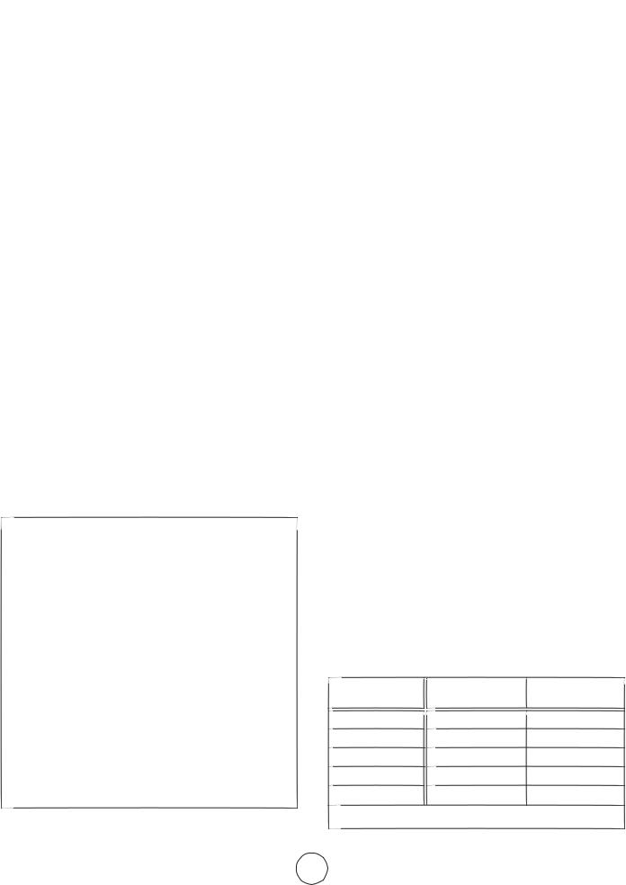
MHU45/MHU75 AND HSU45/HSU75 UNIT DIMENSIONS
(N-NATURAL GAS, P-PROPANE)
HANGING
BRACKETS
AIR
FLOW
HEAT EXCHANGER (ALUMINIZED STEEL)
MOUNTING SLOTS (Typical) 5/16 x 3 Inches (8 x 76 mm)
DIMENSION |
45 |
75 |
|
|
|
|
|
|
A |
12 (305) |
17 (432) |
|
|
|
B |
5-1/2 (140) |
6-1/2 (165) |
|
|
|
C |
4-1/4 (108) |
6-3/4 (171) |
|
|
|
TOP VIEW
|
|
|
|
SERVICE |
LOUVERS |
|
|
|
|
||
|
|
|
|
||
|
|
|
|
||
|
|
|
|
ACCESS PANEL |
|
BACK VIEW |
|
SIDE VIEW |
|||
|
|
|
|
|
|
|
START–UP AND PERFORMANCE CHECK LIST |
|
|||
Job Name: _________________________________________ |
Job No.: ______________________________________ |
Date: ______________________________________ |
|||
Job Location: _______________________________________ |
City: _________________________________________ |
State/Province: ______________________________ |
|||
Installer: __________________________________________ |
City: _________________________________________ |
State/Province: ______________________________ |
|||
Unit Model No.: ____________________________________ |
Serial No.: ____________________________________ |
Service Technician: ___________________________ |
|||
Electrical Connections Tight? ______________________________________________ |
Flue Connections Tight? _________________________________________________ |
Supply Voltage __________________________________________________________ |
Fan Timer Operation Checked? ____________________________________________ |
Gas Piping Connections Tight & Leak-Tested? _________________________________ |
THERMOSTAT |
Motor Amps ____________________________________________________________ |
Calibrated? ____________________________________________________________ |
Furnace Btu Input ________________________________________________________ |
Heat Anticipator Properly Set? |
Line Pressure ____________________________________________________________ |
Level? _________________________________________________________________ |
Manifold Pressure w.c. ____________________________________________________ |
|
Enerco | Compact Unit Heater |
3 |
Operating Instructions and Owner’s Manual |
SHIPPING
The heater is completely assembled. Installation instructions, two mounting brackets (shipped loose), and a flue transition are included. Check the unit for shipping damage. The receiving party should contact the last carrier immediately if any shipping damage is found.
REQUIREMENTS – CSA IN THE USA
Installation of gas unit heaters must conform with local building codes or, in the absence of local codes, with the current National Fuel Gas Code ANSI Z223.1.
Installation in aircraft hangers must be in accordance with the current Standard for Aircraft Hangers ANSI/NFPA No. 409.
Installation in parking structures must be in accordance with the current Standard for Parking Structures ANSI/NFPA No. 88A.
Installation in repair garages must be in accordance with the current Standard for Repair Garages ANSI/NFPA No. 88B.
These units are approved for residential applications. For installation in a residential garage these units must be installed so that burners and ignition source are located no less than 18" (457mm) above floor. Heater must be located or protected to avoid physical damage by vehicles. Refer to the National Fuel Gas Code, ANSI Z223.1, current edition.
Authorities having jurisdiction should be consulted before NFPA installation. Air for combustion and ventilation must conform to the methods outlined in ANSI Z223.1, section 5.3, Air for Combustion and Ventilation, or applicable provisions of local building codes. The National Fuel Gas Code is available from:
American National Standard Institute Inc.
11 West 42nd Street
New York, NY 10036
These units are CSA International design certified. These unit heaters are certified for installation to combustible material as listed in table 1 and on unit rating plate. Accessibility and service clearances must be observed in addition to fire protection clearances.
All electrical wiring and ground for unit must be in accordance with the regulations of the current National Electric Code ANSI/ No. 70.
The National Electric Code is available from:
National Fire Protection Association
1 Batterymarch Park
PO Box 9101
Quincy, MA 02269-9101
TABLE 1
UNIT CLEARANCES
|
Top |
|
Sides |
Access Panel |
|
|||
|
|
|
|
|
|
|
|
|
in |
|
mm |
in |
|
mm |
in |
mm |
|
|
|
|
|
|
|
|
|
|
1 |
|
25 |
1 |
|
25 |
18 |
457 |
|
|
|
|
|
|
|
|
|
|
|
Bottom |
|
Rear |
Single Wall Vent* |
|
|||
in |
|
mm |
in |
|
mm |
in |
mm |
|
|
|
|
|
|
|
|
|
|
|
|
|
|
|
|
|
||
0 |
|
0 |
18 |
|
456 |
6 |
152 |
|
|
|
|
|
|
|
|
|
|
*Except for listed clearance thimbles.
REQUIREMENTS – CSA IN CANADA
The instructions are intended only as a general guide and do not supersede local codes in any way. Authorities having jurisdiction should be consulted before installation. The installation must conform with local building codes or in the absence of local codes, with the current CSA B149.1, Natural Gas and Propane Installation Code. All electrical wiring and grounding for the unit must also comply with the Canadian Electrical Code CSA C22.1, current edition.
These unit heaters are CSA International. certified for the clearances to combustible material listed on the rating plate and table 1. Adequate clearance around air openings into the combustion chamber, clearances from combustible material, and provisions for accessibility and for combustion and ventilation air supply. Provision shall be made for service accessibility to the heater. Note that fire protection clearances may be exceeded to provide additional space for service and accessibility.
GARAGE INSTALLATIONS:
Installation in parking structures must be in accordance with the current Standard for Parking Structures ANSI/NFPA No. 88A.
Installation in repair garages must be in accordance with the current Standard for Repair Garages ANSI/NFPA No. 88B.
1.In a storage area, clearance from heaters to combustible materials must be such that the material shall not attain a temperature above 160°F by continuous operation of the unit.
2.Eight foot minimum clearance from the floor to the bottom of the heater must be maintained. Refer to the CSA B149.1, Natural Gas and Propane Installation Code
AIRCRAFT HANGER:
Installation of gas unit heaters must conform with local building codes or, in the absence of local codes, with the current National Fuel Gas Code ANSI Z223.1.
1.In an area where aircraft are housed or serviced, 10' minimum clearance from highest surface of aircraft to bottom of the heater must be maintained.
2.In other areas, 8' minimum clearance from the floor to bottom of heater must be maintained.
3.Heaters should be located so as to be protected from damage from aircraft or other appliances needed for servicing of aircraft. Refer to requirements of the enforcing authorities.
Enerco | Compact Unit Heater |
4 |
Operating Instructions and Owner’s Manual |
Theseunitsareapprovedforresidentialapplications.For installation in a residential garage, these units must be installed so that burners and ignition source are located no less than 18” (457mm) above floor. Heater must be located or protected to avoid physical damage by vehicles. Refer to CSA B149.1, Natural Gas and Propane Installation Code current edition.
Inaconfinedarea,theheatermustbeinstalledinaccordancewith the CSAB149.1,NaturalGasandPropaneInstallationCode.Be suretocheck withlocalcodesandordinancesforadditional requirements.
UNIT HEATER INSTALLATION
The installation shall conform with local building codes or,in the absence
of local codes,with the National Fuel Gas Code, ANSI Z223.1 /
NFPA 54 or the CSA B 149.1, Natural Gas and Propane Installation Code.
The appliance and venting system is to be inspected once a year by a qualified service agency.
Unitisshippedreadyforinstallation.Unitmaybeinstalled
as shownin figure 1 orinverted180odependingondesired location asgovernedbyclearances,ventconnection,air direction,gas
supply,electricalsupplyandserviceaccessibility.
1.If installingunitinaninvertedposition: Removeand retain screws securing door and rotate door 180o. Secure with retained screws. Rotatelouversdirectingairflowas desired.
2.Chooselocationformountingbrackets.
3.Remove and retain three screws along top edge (bottom edge wheninverted)of frontofunit.
4.Alignscrewholesonmountingbracketwithholesalong top edge (eitheruprightorinverted)ofunit.Secure one mounting bracket tofrontofunitwithretained screws. Secureothermounting brackettobackofunitwith screws providedinbagassembly containingfluetransition.
5.Tosupportunit,securemountingbrackettoceilingjoist or truss. Unit may also hang on rods as shown in figure 1 .
INSTALLUNITHEATER
SUPPORT
MOUNTING RODS
BRACKETS(2)
FIGURE1
COMBUSTIONANDVENTILATIONAIR
Adequatefacilitiesforsupplyingairforcombustionand ventilation mustbeprovidedinaccordancewiththelatestedition ofsection 5.3,Air forCombustionandVentilation,ofthe
NationalFuelGas Code, ANSI Z223.1, in the U.S.A., CSA B149.1 Natural Gas and PropaneInstallationCode in Canada,
orapplicableprovisions oflocalbuilding codes.
Allgasfiredappliancesrequireairtobeusedforthecombustion process.Inmanybuildingstoday,thereisanegativeindoorair pressurecausedbyexhaustfans,etc.Ifsufficientquantitiesof combustionairarenotavailable,theheateroranother appliancewilloperateinaninefficientmanner,resultingin incompletecombustionwhichcanresultintheproductionof excessivecarbonmonoxide.
CAUTION Insufficientcombustionaircancauseheadaches, nausea,dizziness,asphyxiationordeath.
Ifindoorairistobeusedforcombustion,itmustbefreeofthe followingsubstancesorthelifeoftheheatexchangerwillbe adverselyaffected:chlorine,carbontetrachloride,cleaningsolvent, halogenrefrigerants,acids,cementsandglues,printinginks, fluorides,paintremovers,varnishes,oranyothercorrosives.
VENTING
A – GENERAL RECOMMENDATIONS AND REQUIREMENTS
NOTE: The vent is a passageway, vertical or nearly so, used to convey flue gases from an appliance, or its vent connector, to the outsideatmosphere.Theventconnectoristhepipeorductthat connectsafuel-gasburningappliancetoaventorchimney.
Unitheatersmustbeventedincompliancewithalllocalcodesor requirementsofthelocalutility,thecurrentstandardsofthe (American)NationalFuelGasCode,ANSIZ223.1or(Canada)CSA B149.1NaturalGasandPropaneInstallationCode,andthe followinginstructions.
Ametalstamped/extrudedtransitionissuppliedwiththiscertified unit.Itmustnotbemodifiedoralteredandmustbeinstalledon theoutletoftheinduceddraftblowerassemblypriortothe installationoftheventorventconnector.Failuretocomplywith thisrequirementwillvoidthecertificationoftheunitbythe approvalagencies.Alljointsshallbesecuredwithatleasttwo corrosion resistant screws. All joints must be checked for gas tightnessafterinstallation.
TABLE2
MAXIMUMVENTLENGTHS
HORIZONTALVENTS
No.of |
ft |
m |
Elbows |
|
|
1 |
25 |
7.6 |
2 |
20 |
6.1 |
3 |
15 |
4.6 |
4 |
10 |
3.0 |
5 |
5 |
1.5 |
Maximumlengthofventconnectornottoexceed30ft.(9.1m).
Enerco | Compact Unit Heater |
5 |
Operating Instructions and Owner’s Manual |
 Loading...