


Starting Serial Numbers - Page 2
OPERATING INSTRUCTIONS AND OWNER’S MANUAL
MR. HEATER
MODEL |
MHU 45 |
MHU 75 |
|
|
|
READ INSTRUCTIONS CAREFULLY: Read and follow all instructions. Place instructions in a safe place for future reference. Do not allow anyone who has not read these instructions to assemble, light, adjust or operate the heater.
HEATSTAR
MODEL |
HSU 45 |
HSU 75 |
|
|
|
COMPACT UNIT HEATER
WARNING: Improper installation, adjustment, alteration, service or maintenance can cause injury or property damage. Refer to this manual. For assistance or additional information consult a qualified installer, service agency or the gas supplier.
—
WHAT TO DO IF YOU SMELL GAS
•Open Windows
•DO NOT try to light any appliance.
•DO NOT use electrical switches.
•DO NOT use any telephone in your house. Immediately call your local gas supplier from a neighbor’s telephone. Follow the gas supplier’s instructions.
•Do not touch any electrical switch; do not use any phone in your building.
•Installation and service must be performed by a qualified installer, service agency or the gas supplier.
•If you cannot reach your gas supplier, call the Fire Department.
FOR YOUR SAFETY:
Do not store or use gasoline or other flammable vapors and liquids in the vicinity of this or any other appliance.
WARNING: If the information in these instructions are not followed exactly, a fire or explosion may result causing property damage, personal injury or loss of life.
ENERCO GROUP, INC., 4560 W. 160TH ST., CLEVELAND, OHIO 44135 • 216-916-3000 |
10/09 #60016 |

Starting Serial Numbers |
|
|
MHU45NG |
-- |
260045-09001001 |
MHU45LP |
-- |
260145-09001001 |
MHU75NG |
-- |
260775-09001001 |
MHU75LP |
-- |
260875-09001001 |
HSU45NG |
-- |
160245-09001001 |
HSU45LP |
-- |
160345-09001001 |
HSU75NG |
-- |
160775-09001001 |
HSU75LP |
-- |
160975-09001001 |
|
|
|
Enerco | Compact Unit Heater |
2 |
Operating Instructions and Owner’s Manual |
|
|
|
|
|
|
|
WARNING: |
|
|
|
WARNING: |
|
|
|
|
|
||||
|
YOUR SAFETY IS IMPORTANT TO YOU AND TO OTHERS, |
|
FIRE, BURN, INHALATION, AND EXPLOSION HAZARD. |
|
||
|
SO PLEASE READ THESE INSTRUCTIONS BEFORE YOU |
|
KEEP SOLID COMBUSTIBLES, SUCH AS BUILDING |
|
||
|
OPERATE THIS HEATER. |
|
|
|
MATERIALS, PAPER OR CARDBOARD, A SAFE DISTANCE |
|
|
|
|
|
|
AWAY FROM THE HEATER AS RECOMMENDED BY THE |
|
GENERAL HAZARD WARNING: |
|
|
|
|||
|
|
|
INSTRUCTIONS NEVER USE THE HEATER IN SPACES |
|
||
|
FAILURE TO COMPLY WITH THE PRECAUTIONS AND |
|
|
WHICH DO OR MAY CONTAIN VOLATILE OR AIRBORNE |
|
|
|
INSTRUCTIONS PROVIDED WITH THIS HEATER, CAN |
|
|
COMBUSTIBLES, OR PRODUCTS SUCH AS GASOLINE, |
|
|
|
RESULT IN DEATH, SERIOUS BODILY INJURY AND |
|
|
|
SOLVENTS, PAINT THINNER, DUST PARTICLES OR |
|
|
PROPERTY LOSS OR DAMAGE FROM HAZARDS OF |
|
|
|
UNKNOWN CHEMICALS. |
|
|
FIRE, EXPLOSION, BURN, ASPHYXIATION, CARBON |
|
|
|
|
|
|
|
|
|
|
|
|
|
MONOXIDE POISONING, AND/OR ELECTRICAL SHOCK. |
|
WARNING: |
|
||
|
ONLY PERSONS WHO CAN UNDERSTAND AND FOLLOW |
|
|
|||
|
|
The State of California requires the following warning: |
|
|||
|
THE INSTRUCTIONS SHOULD USE OR SERVICE THIS |
|
|
|
|
|
|
|
|
|
COMBUSTION BY-PRODUCTS PRODUCED WHEN USING |
|
|
|
HEATER. |
|
|
|
|
|
|
|
|
|
THIS PRODUCT CONTAIN CARBON MONOXIDE, A |
|
|
|
IF YOU NEED ASSISTANCE OR HEATER INFORMATION |
|
|
|||
|
|
CHEMICAL KNOWN TO THE STATE OF CALIFORNIA |
|
|||
|
SUCH AS AN INSTRUCTION MANUAL, LABELS, ETC. |
|
|
|
||
|
|
|
TO CAUSE CANCER AND BIRTH DEFECTS (OR OTHER |
|
||
|
CONTACT THE MANUFACTURER. |
|
|
|
|
|
|
|
|
|
REPRODUCTIVE HARM). |
|
|
|
|
|
|
|
|
|
|
|
|
|
|
|
|
|
|
|
|
|
|
|
CONTENTS |
|
|
|
|
|
|
|
|
|
|
|
||
UNIT DIMENSIONS................................................................... |
|
4 |
|
|
|
|
SHIPPING................................................................................. |
|
5 |
|
|
|
|
REQUIREMENTS........................................................................ |
|
5 |
|
|
|
|
UNIT HEATER INSTALLATION.................................................... |
|
6 |
|
|
|
|
COMBUSTION & VENTILATION AIR.......................................... |
|
6 |
|
|
|
|
VENTING.............................................................................. |
6-10 |
|
|
|
||
ELECTRICAL CONNECTIONS..................................................... |
|
10 |
|
|
|
|
GAS CONNECTION.................................................................. |
|
11 |
|
|
|
|
LEAK CHECK........................................................................... |
|
11 |
|
|
|
|
START-UP OPERATION............................................................. |
|
11 |
|
|
|
|
HEATING SEQUENCE OF OPERATION....................................... |
|
12 |
|
|
|
|
IGNITION CONTROL LED......................................................... |
|
12 |
|
|
|
|
ADJUSTMENTS........................................................................ |
|
12 |
|
|
|
|
SERVICE.................................................................................. |
|
13 |
|
|
|
|
WIRING DIAGRAM.................................................................. |
|
14 |
|
|
|
|
PARTS LIST.............................................................................. |
|
16 |
|
|
|
|
WARRANTY............................................................................. |
|
18 |
|
|
|
|
|
|
|
|
|
|
|
Enerco | Compact Unit Heater |
3 |
Operating Instructions and Owner’s Manual |
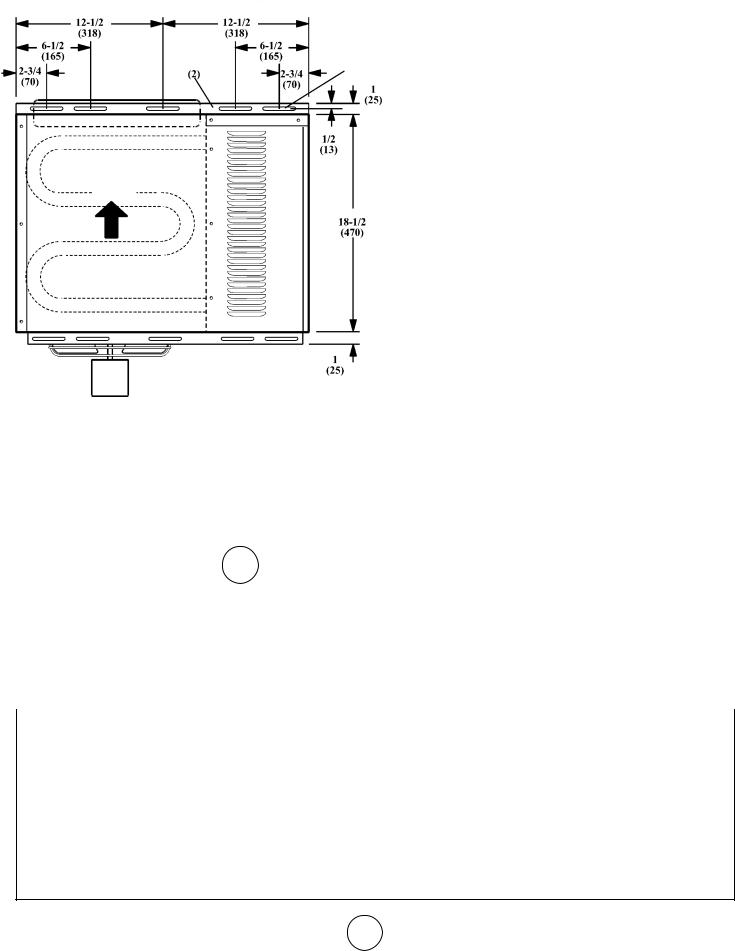
MHU45/MHU75 AND HSU45/HSU75 UNIT DIMENSIONS
(N-NATURAL GAS, P-PROPANE)
HANGING
BRACKETS MOUNTING SLOTS (Typical) 5/16 x 3 Inches (8 x 76 mm)
AIR
FLOW
HEAT EXCHANGER (ALUMINIZED STEEL)
DIMENSION |
45 |
75 |
|
|
|
|
|
|
A |
12 (305) |
17 (432) |
|
|
|
B |
5-1/2 (140) |
6-1/2 (165) |
|
|
|
C |
4-1/4 (108) |
6-3/4 (171) |
|
|
|
TOP VIEW
|
|
|
|
|
SERVICE |
LOUVERS |
|
|
|
|
|
||
|
|
|
|
|
||
|
|
|
|
|
||
|
|
|
|
|
ACCESS PANEL |
|
BACK VIEW |
|
SIDE VIEW |
||||
|
|
|
|
|
|
|
|
START–UP AND PERFORMANCE CHECK LIST |
|
||||
Job Name:___________________________________________ |
Job No.:_______________________________________ |
Date:_______________________________________ |
||||
Job Location:_________________________________________ |
City:__________________________________________ |
State/Province:_______________________________ |
||||
Installer:_____________________________________________ |
City:__________________________________________ |
State/Province:_______________________________ |
||||
Unit Model No.:______________________________________ |
Serial No.:_____________________________________ |
Service Technician:____________________________ |
||||
Electrical Connections Tight?________________________________________________ |
Flue Connections Tight?___________________________________________________ |
Supply Voltage____________________________________________________________ |
Fan Timer Operation Checked?_____________________________________________ |
Gas Piping Connections Tight & Leak-Tested?___________________________________ |
THERMOSTAT |
Motor Amps_____________________________________________________________ |
Calibrated?_____________________________________________________________ |
Furnace Btu Input_________________________________________________________ |
Heat Anticipator Properly Set? |
Line Pressure_____________________________________________________________ |
Level?__________________________________________________________________ |
Manifold Pressure w.c._ ____________________________________________________ |
|
Enerco | Compact Unit Heater |
4 |
Operating Instructions and Owner’s Manual |
SHIPPING
The heater is completely assembled. Installation instructions, two mounting brackets (shipped loose), and a flue transition are
included. Check the unit for shipping damage. The receiving party should contact the last carrier immediately if any shipping damage is found.
REQUIREMENTS – CSA IN THE USA
Installation of gas unit heaters must conform with local building codes or, in the absence of local codes, with the current National
Fuel Gas Code ANSI Z223.1.
Installation in aircraft hangers must be in accordance with the current Standard for Aircraft Hangers ANSI/NFPA No. 409.
Installation in parking structures must be in accordance with the current Standard for Parking Structures ANSI/NFPA No. 88A.
Installation in repair garages must be in accordance with the current Standard for Repair Garages ANSI/NFPA No. 88B.
These units are approved for residential applications. For installation in a residential garage these units must be installed so that burners and ignition source are located no less than 18”
(457mm) above floor. Heater must be located or protected to avoid physical damage by vehicles. Refer to the National Fuel Gas
Code, ANSI Z223.1, current edition.
Authorities having jurisdiction should be consulted before NFPA installation. Air for combustion and ventilation must conform to the methods outlined in ANSI Z223.1, section 5.3, Air for
Combustion and Ventilation, or applicable provisions of local building codes. The National Fuel Gas Code is available from:
American National Standard Institute Inc.
11 West 42nd Street
New York, NY 10036
These units are CSA International design certified. These unit heaters are certified for installation to combustible material as listed in table 1 and on unit rating plate. Accessibility and
service clearances must be observed in addition to fire protection clearances.
All electrical wiring and ground for unit must be in accordance with the regulations of the current National Electric Code ANSI/ No. 70.
The National Electric Code is available from:
National Fire Protection Association 1 Batterymarch Park
PO Box 9101
Quincy, MA 02269-9101
TABLE 1
UNIT CLEARANCES
|
Top |
|
Sides |
Access Panel |
|
|||
|
|
|
|
|
|
|
|
|
in |
|
mm |
in |
|
mm |
in |
mm |
|
|
|
|
|
|
|
|
|
|
1 |
|
25 |
1 |
|
25 |
18 |
457 |
|
|
|
|
|
|
|
|
|
|
|
Bottom |
|
Rear |
Single Wall Vent* |
|
|||
in |
|
mm |
in |
|
mm |
in |
mm |
|
|
|
|
|
|
|
|
|
|
|
|
|
|
|
|
|
|
|
0 |
|
0 |
18 |
|
456 |
6 |
152 |
|
|
|
|
|
|
|
|
|
|
*Except for listed clearance thimbles.
REQUIREMENTS – CSA IN CANADA
The instructions are intended only as a general guide and do not supersede local codes in any way. Authorities having jurisdiction should be consulted before installation. The installation must conform with local building codes or in the absence of local codes, with the current CSA B149.1, Natural Gas and Propane Installation Code. All electrical wiring and grounding for the unit must also comply with the Canadian Electrical Code CSA C22.1, current edition.
These unit heaters are CSA International certified for the clearances to combustible material listed on the rating plate and table 1. Adequate clearance around air openings into the
combustion chamber, clearances from combustible material, and provisions for accessibility and for combustion and ventilation air supply. Provision shall be made for service accessibility to the heater. Note that fire protection clearances may be exceeded to provide additional space for service and accessibility.
GARAGE INSTALLATIONS:
Installation in parking structures must be in accordance with the current Standard for Parking Structures ANSI/NFPA No. 88A.
Installation in repair garages must be in accordance with the current Standard for Repair Garages ANSI/NFPA No. 88B.
1.In a storage area, clearance from heaters to combustible materials must be such that the material shall not attain a temperature above 160°F by continuous operation of the unit.
2.Eight foot minimum clearance from the floor to the bottom of the heater must be maintained. Refer to the CSA B149.1, Natural Gas and Propane Installation Code
AIRCRAFT HANGER:
Installation of gas unit heaters must conform with local building codes or, in the absence of local codes, with the current National
Fuel Gas Code ANSI Z223.1.
1.In an area where aircraft are housed or serviced, 10’ minimum clearance from highest surface of aircraft to bottom of the heater must be maintained.
2.In other areas, 8’ minimum clearance from the floor to bottom of heater must be maintained.
3.Heaters should be located so as to be protected from damage from aircraft or other appliances needed for servicing of aircraft. Refer to requirements of the enforcing authorities.
Enerco | Compact Unit Heater |
5 |
Operating Instructions and Owner’s Manual |
These units are approved for residential applications. For installation in a residential garage, these units must be installed so that burners and ignition source are located no less than 18”
(457mm) above floor. Heater must be located or protected to avoid physical damage by vehicles. Refer to CSA B149.1, Natural Gas and Propane Installation Code current edition.
In a confined area, the heater must be installed in accordance with the CSA B149.1, Natural Gas and Propane Installation Code. Be sure to check with local codes and ordinances for additional requirements.
UNIT HEATER INSTALLATION
Unit is shipped ready for installation. Unit may be installed as shown in figure 1 or inverted 180o depending on desired location as governed by clearances, vent connection, air direction, gas supply, electrical supply and service accessibility.
1.If installing unit in an inverted position: Remove and retain screws securing door and rotate door 180o. Secure with retained screws. Rotate louvers directing airflow as desired.
2.Choose location for mounting brackets.
3.Remove and retain three screws along top edge (bottom edge when inverted) of front of unit.
4.Align screw holes on mounting bracket with holes along top edge (either upright or inverted) of unit. Secure one mounting bracket to front of unit with retained screws.
Secure other mounting bracket to back of unit with screws provided in bag assembly containing flue transition.
5.To support unit, secure mounting bracket to ceiling joist or truss. Unit may also hang on rods as shown in figure 1.
INSTALL UNIT HEATER
SUPPORT MOUNTING RODS BRACKETS (2)
FIGURE 1
COMBUSTION AND VENTILATION AIR
Adequate facilities for supplying air for combustion and ventilation must be provided in accordance with the latest edition of section 5.3, Air for Combustion and Ventilation, of the National Fuel
Gas Code, ANSI Z223.1, in the U.S.A., CSA B149.1 Natural Gas and Propane Installation Code, or applicable provisions of local building codes.
All gas fired appliances require air to be used for the combustion process. In many buildings today, there is a negative indoor
air pressure caused by exhaust fans, etc. If sufficient quantities of combustion air are not available, the heater or another or another appliance will operate in an inefficient manner, resulting in incomplete combustion which can result in the production of excessive carbon monoxide.
CAUTION Insufficient combustion air can cause headaches, nausea, dizziness, asphyxiation or death.
If indoor air is to be used for combustion, it must be free of the following substances or the life of the heat exchanger will be adversely affected: chlorine, carbon tetrachloride, cleaning solvent, halogen refrigerants, acids, cements and glues, printing inks, fluorides, paint removers, varnishes, or any other corrosives.
VENTING
A – GENERAL RECOMMENDATIONS AND REQUIREMENTS
NOTE: The vent is a passageway, vertical or nearly so, used to convey flue gases from an appliance, or its vent connector, to the outside atmosphere. The vent connector is the pipe or duct that connects a fuel-gas burning appliance to a vent or chimney.
Unit heaters must be vented in compliance with all local codes or requirements of the local utility, the current standards of the
(American) National Fuel Gas Code, ANSI Z223.1 or (Canada)
CSA B149.1 Natural Gas and Propane Installation Code, and the following instructions.
A metal stamped/extruded transition is supplied with this certified unit. It must not be modified or altered and must be installed
on the outlet of the induced draft blower assembly prior to the installation of the vent or vent connector. Failure to comply with this requirement will void the certification of the unit by the approval agencies. All joints shall be secured with at least two corrosion resistant screws. All joints must be checked for gas tightness after installation.
TABLE 2
MAXIMUM VENT LENGTHS
HORIZONTAL VENTS
No. of |
ft |
m |
Elbows |
|
|
|
|
|
|
|
|
1 |
25 |
7.6 |
|
|
|
2 |
20 |
6.1 |
|
|
|
3 |
15 |
4.6 |
|
|
|
4 |
10 |
3.0 |
|
|
|
5 |
5 |
1.5 |
|
|
|
Maximum length of vent connector not to exceed 30 ft. (9.1m).
Enerco | Compact Unit Heater |
6 |
Operating Instructions and Owner’s Manual |
B – VERTICAL VENTS USING METAL VENT PIPE – COMMERCIAL AND RESIDENTIAL INSTALLATIONS
MHU/HSU compact unit heaters are listed as Category I appliances for vertical vent installations.
1.MHU/HSU unit heaters are to be used with NFPAor ANSIapproved chimneys, U.L. listed type B-1 gas vents, single wall metal pipe, or listed chimney lining system for gas venting where applicable, as well as the modifications and limitations listed in figure 2. Seal single wall vent material according to the section A - General Recommendations and Requirements.
2.The vent connector shall be 3” (76mm) diameter on 45 units.
In all cases, a flue transition piece (supplied) is required to fit over the outlet of the induced draft assembly on the appliance.
3.Keep the vent connector runs as short as possible with a minimum number of elbows. Refer to the (American)
National Fuel Gas Code ANSI Z223.1 or (Canada) CSA B149.1
Natural Gas and Propane Installation Code for maximum vent and vent connector lengths. Horizontal run of the vent connector from the induced draft blower to the chimney/vent cannot exceed the values in table 2.
4.When the length of a single wall vent, including elbows, exceeds 5 feet (1.5m), the vent shall be insulated along its entire length with a minimum of 1/2” thick foil faced fiberglass 1-1/2# density insulation. If a single wall vent is
used in an unheated area it shall be insulated. Failure to do so will result in condensation of flue gases.
5.The unit may be vented vertically as a single appliance or as a common vent with other gas-fired appliances. In common venting situations, vent connectors for other appliances must maintain a 4” (100mm) vertical separation between the vent connectors. Refer to common venting tables in the
(American) National Fuel Gas Code ANSI Z223.1 or (Canada)
CSA B149.1 Natural Gas and Propane Installation Code for proper vent size.
6.Clearance to combustible material is 6” (152mm) for single wall vent material except where a listed clearance thimble is used. Clearance to combustible material for type B-1 vent or factory-built chimney is per manufacturer’s instructions.
7.The vent connector shall be supported without any dips or sags. Vertical vents shall be supported in accordance with their listing and manufacturers’ instructions. All horizontal vent connector runs shall have a slope up to the vertical vent of at least 1/4” per foot (1mm per 50mm).
8.All vertical type B-1 vents, single wall vents, or listed chimney lining system must be terminated with a listed vent cap or listed roof assembly.
9.The vent must extend at least 3’ (1m) above the highest point where it passes through a roof of a building and at least 2’
(0.6m) higher than any part of a building within a horizontal distance of 10’ (3.05m) unless otherwise specified by the
(American) National Fuel Gas Code, ANSI Z223.1 or (Canada) CAN/CGA-B149 Installation Code. The vent must extend at least 5’ (1.6m) above the highest connected equipment flue collar.
C – HORIZONTAL VENTING – GENERAL
Common venting is not allowed when horizontally venting the unit heater.
The minimum horizontal vent length is three feet (914mm).
1.If possible, do not terminate the horizontal vent through a wall that is exposed to prevailing wind. Exposure to excessive winds can affect unit performance.
2.Vent termination must be free from obstructions and at least 12” (306mm) above grade level and maximum snow height.
VENT TERMINATION ON SINGLE WALL VENT
SINGLE WALL TERMINATION
ROOF FLASHING
ROOF PITCHED
FROM 0” TO 45”
2” CLEARANCE SHALL NOT BE A THIMBLE CONCEALED SPACE
DOUBLE WALL (TYPE B-1) TERMINATION
ROOF FLASHING
ROOF PITCHED
FROM 0” TO 45”
12” MAX |
CLEARANCE TO BE AS |
|
|
|
SPECIFIED ON TYPE “B” |
|
VENT PIPE |
SEAL JOINT BETWEEN SINGLE WALL VENT
AND “B”VENT AND THE ANNULAR SPACE OF THE “B” VENT
FIGURE 2
3.Do not terminate vent directly below roof eaves or above a walkway, or any other area where condensate dripping may be troublesome and may cause some staining. Avoid windows where steam may cause fogging or ice buildup.
4.When horizontally vented, minimum clearance for termination from any door, window, gravity air inlet, gas or electric meter, regulators, and relief equipment is 4 ft. (1.2m) for U.S. installations. Refer to NFPA 54/ANSI Z223.1 in the U.S.A. and
CSA B149.1 Natural Gas and Propane Installation Code and
.2 in Canada or with authorities having local jurisdiction. In Canada, vent termination must have a minimum 6 ft. (1.8 m) horizontal clearance from gas and electric meters and relief devices as specified in the Canadian B149.1, Natural Gas Installation Code.
Enerco | Compact Unit Heater |
7 |
Operating Instructions and Owner’s Manual |
5.Vent termination must be a minimum of 4’ (1.2m) below or 4’ (1.2m) horizontally from any soffit vent or under-eave vent.
6.Vent must be a minimum of 6’ from an inside corner formed by two exterior walls. If possible, leave a 10’ clearance.
7.Vent termination must be a minimum of 10’ (3m) from any forced air inlet (includes fresh air inlet for other appliances, such as a dryer).
8.When termination is routed through an exterior combustible wall the vent must be supported using a listed clearance thimble. Where local authorities permit, a single section
of type B-1 vent pipe may be used as an alternative to the thimble. When using a type B-1 vent termination use the clearances specified by the vent manufacturer. Seal the connection between the single wall and double wall pipes and the annular space of the double wall pipe as shown in figure 2. Inside edge of vent termination tee must be at least 12 inches from outside wall as shown in figure 3.
9.For horizontal venting, the vent pipe shall be supported with hangers no more than 3ft. (1m) apart to prevent movement after installation.
D – HORIZONTAL VENTING – COMMERCIAL
1.Horizontal commercial installations are for buildings which are not attached to living spaces. The vent may be single wall vent material installed according to the sections
Venting A - General Recommendations and Requirements and C - Horizontal Venting General and D - Horizontal Venting - Commercial. Refer to figure 3.
2.The vent pipe diameter for horizontal commercial installations shall be 4V” (76mm) on 45 units. In all cases, a flue transition piece (supplied) is required to fit over the outlet of the induced draft assembly on the appliance.
3.Refer to table 2 for maximum vent connector lengths.
4.Select a wall termination point that will maintain ¼” rise per foot slope of horizontal run of vent pipe. The vent may be single wall material minimum 26 GSG (0.46mm) galvanized steel or equivalent grade stainless steel. Seal
single wall vent material according to the section A - General
Recommendations and Requirements.
5.For upward sloped vent a condensate tee and drain must be installed within the first 5’ (1.5m) from the unit heater to protect the appliance. If a flexible condensate drain line is used, the drain line must include a loop entering the structure. If the unit is shut down for an extended period of time and will be exposed to sub-freezing temperatures, the condensate may freeze.
E – HORIZONTAL VENTING – RESIDENTIAL
1.For horizontal residential installations these units are certified as Category I appliances. The vent may be single wall material minimum 25 GSG (0.46mm) galvanized steel or equivalent grade stainless steel. Venting A - General Recommendations and Requirements and C - Horizontal Venting General and E - Horizontal Venting - Residential.
Refer to figure 6.
2.The vent pipe diameter for horizontal residential installations shall be 4” (100mm) on 45 units. A standard vent transition is required at unit in addition to the transition supplied with the unit.
3.The maximum vent length is 5’ (1.5m) plus one 90-degree elbow. The minimum length is 3’(.91m).
4.The vent must maintain a ¼” rise per foot of slope upwards toward the termination.
CONDENSATE DRAIN THROUGH TEE PIPE AND DRAIN LOOP
UPWARD SLOPE ON HORIZONTAL VENT-COMMERCIAL INSTALLATION
MAY BE SINGLE WALL (26 GSG) GALV. OR EQUIV. STAINLESS STEEL SEALED ACCORDING TO THESE INSTALLATION INSTRUCTIONS. SLOPE: + 1/4 INCH FOR 1 FOOT RUN MINIMUM.
FLUE TRANSITION (PROVIDED)
LISTED THIMBLE
THROUGH COMBUSTIBLE
WALL
INDUCED DRAFT BLOWER
NOTE - MINIMUM HORIZONTAL LENGTH 3 FT. (914MM), |
|
NOT INCLUDING CAP FOR TERMINATION. REFER TO TABLE |
DRAIN LOOP WITH WATER |
2 FOR MAXIMUM LENGTH AND NUMBER OF ELBOWS. |
TRAP (TO CONDENSATE DRAIN) |
12 INCHES MIN.
(30.5 CM)
VENT TERMINATION
CAP
12” (30.5 CM)
MINIMUM ABOVE ALL HIGHEST SNOWFALL
COMMON VENTING NOT ALLOWED WHEN HORIZONTALLY VENTING THE UNIT HEATER
FIGURE 3
Enerco | Compact Unit Heater |
8 |
Operating Instructions and Owner’s Manual |
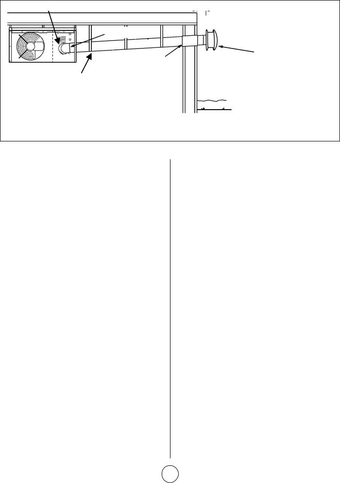
INDUCED DRAFT BLOWER |
HORIZONTAL VENTING - RESIDENTIAL INSTALLATION |
UPWARD SLOPE |
|
|
12 INCHES |
|
MIN. (30.5CM) |
|
FLUE TRANSITION |
|
(PROVIDED) |
VENT TERMINATION CAP
LISTED THIMBLE THROUGH
COMBUSTION WALL
MAY BE SINGLE WALL (26 GSG) GALV. OR EQUIV. STAINLESS STEEL SEALED ACCORDING TO THESE INSTALLATION INSTRUCTIONS OR A SINGLE SECTION OF TYPE B-1 VENT. SLOPED: + 1/4 INCH FOR 1 FOOT RUN MINIMUM.
NOTE - MINIMUM HORIZONTAL LENGTH 3FT. (914MM), NOT INCLUDING CAP FOR TERMINATION.
MAXIMUM HORIZONTAL LENGTH 5FT. (1.5M) PLUS ONE
90-DEGREE ELBOW.
COMMON VENTING NOT ALLOWED WHEN HORIZONTALLY VENTING THE UNIT HEATER.
FIGURE 6
F – VENTING USING A MASONRY CHIMNEY |
7. |
The space between liner and chimney wall should NOT |
||
The following additional requirements apply when a lined masonry |
|
be insulated with puffed mica or any other loose granular |
||
|
insulating material. |
|||
chimney is being used to vent the compact unit heater. |
|
|||
8. |
If type B-1 vent or an insulated flexible vent pipe cannot be |
|||
1. |
Masonry chimneys used to vent Category I units heaters |
|||
|
used as liners, the chimney must be rebuilt to accommodate |
|||
|
must be either tile-lined or lined with a listed metal lining |
|
||
|
|
one of these methods or some alternate approved method |
||
|
system or dedicated gas vent. Unlined masonry chimneys are |
|
||
|
|
must be found to vent the appliance. When inspection |
||
|
prohibited. A category I appliance must never be connected |
|
||
|
|
reveals that an existing chimney is not safe for the intended |
||
|
to a chimney that is servicing a solid fuel appliance. If a |
|
||
|
|
purpose, it shall be rebuilt to conform to nationally |
||
|
fireplace chimney flue is used to vent this appliance, the |
|
||
|
|
recognized standards, lined or relined with suitable materials |
||
|
fireplace opening must be permanently sealed. |
|
||
|
|
or replaced with a gas vent or chimney suitable for venting |
||
|
|
|
||
2. |
A fan assisted unit heater may be commonly vented into an |
|
unit heaters. The chimney passageway must be checked |
|
|
existing lined masonry chimney provided: |
|
periodically to ensure that it is clear and free of obstructions. |
|
•The chimney is currently serving at least one draft-hood G – REMOVAL OF UNIT FROM COMMON VENT
|
equipped appliance. |
In the event that an existing unit heater is removed from a venting |
||
• |
|
|||
The vent connector and chimney are sized in accordance |
system commonly run with separate gas appliances, the venting |
|||
|
with venting tables in the (American) National Fuel Gas |
system is likely to be too large to properly vent the remaining |
||
|
attached appliances. The following test should be conducted while |
|||
|
Code ANSI Z223.1 or (Canada) CSA B149.1 Natural Gas |
|||
|
each appliance is in operation and the other appliances are not in |
|||
|
and Propane Installation Code. |
|||
|
operation, yet remain connected to the common venting system. |
|||
IMPORTANT Single appliance venting of a fan assisted unit |
||||
If the venting system has been installed improperly, the system |
||||
heater into a tile lined masonry chimney (interior or outside wall) |
||||
must be corrected. |
||||
is prohibited. The chimney must first be lined with either type B-1 |
||||
1. |
Seal any unused openings in the common venting system. |
|||
vent or an insulated single wall flexible vent lining system, sized |
||||
|
|
|||
in accordance with venting tables in the (American) National Fuel |
2. |
Visually inspect the venting system for proper size and |
||
Gas Code ANSI Z223.1 or (Canada) CSA B149.1 Natural Gas and |
|
horizontal pitch. Determine there is no blockage or |
||
Propane Installation Code. |
|
restriction, leakage, corrosion, or other deficiencies which |
||
3. A type B-1 vent or masonry chimney liner shall terminate |
|
could cause an unsafe condition. |
||
|
|
|||
above the roof surface with a listed cap or a listed roof |
3. |
If practical close all building doors and windows and all |
||
assembly in accordance with the terms of their respective |
|
doors between the space in which the appliances remaining |
||
listings and the vent manufacturer’s instructions. |
|
connected to the common venting system are located and |
||
4. Do not install a manual damper, barometric draft regulator, or |
|
other spaces of the building. Turn on clothes dryers and any |
||
|
appliances not connected to the common venting system. |
|||
flue restrictor between the unit heater and the chimney. |
|
|||
|
Turn on any exhaust fans, such as range hoods and bathroom |
|||
5. If type B-1 double-wall vent is used inside a chimney, no other |
|
|||
|
exhausts, so they will operate at maximum speed. Do not |
|||
appliance can be vented into the chimney. Outer wall of type |
|
|||
|
operate a summer exhaust fan. Close fireplace dampers. |
|||
B-1 vent pipe must not be exposed to flue products. |
|
|||
4. |
Follow the lighting instructions. Place the appliance being |
|||
6. Insulation for the flexible vent pipe must be an encapsulated |
||||
|
inspected in operation. Adjust thermostat so appliance will |
|||
fiberglass sleeve recommended by the flexible vent pipe |
|
|||
|
operate continuously. |
|||
manufacturer. |
|
|||
|
|
|||
Enerco | Compact Unit Heater |
9 |
Operating Instructions and Owner’s Manual |

|
LINE VOLTAGE FIELD WIRING |
|
UNIT |
L1 |
BLACK |
|
BLACK |
|
WHITE |
|
WHITE |
EQUIPMENT |
|
GROUND |
|
BLACK WIRE WITH WHITE TAPE OR
WHITE WIRE WITHOUT TAPE
FIGURE 7
GAS SUPPLY CONNECTION
|
MANUAL |
|
MAIN SHUT-OFF VALVE |
|
(FURNISHED BY INSTALLER) |
GROUNDED |
|
JOINT UNION |
|
1/8 NPT |
GAS FLOW |
PLUGGED TAP |
|
DRIP LEG |
|
FIGURE 8
GAS SUPPLY TO UNIT HEATER
MANUAL MAIN SHUT-OFF VALVE
WILL NOT HOLD NORMAL TEST
PRESSURE ISOLATE GAS VALVE
CAP
UNIT HEATER
FIGURE 9
5.Test for spillage at the draft hood relief opening after five minutes of main burner operation. Use the flame of a match or candle, or smoke from a cigarette, cigar, or pipe.
6.After it has been determined that each appliance remaining connected to the common venting system properly vents when tested as outlined above, return doors, windows, exhaust fans, fireplace dampers and any other gas-burning appliance to their previous condition of use.
7.If improper venting is observed during any of the above tests, the common venting system must be corrected. The common venting system should be resized to approach the minimum size as determined by using the appropriate tables in Appendix G in the current standards of the National Fuel
Gas Code, ANSI Z223-1 in the U.S.A. and the appropriate
Category I Natural Gas and Propane appliances venting sizing tables in the current standards of the CSA B149.1 Natural Gas and Propane Installation Code in Canada.
NOTE Local codes may supersede any of the above provisions.
ELECTRICAL CONNECTIONS
NOTE The MHU/HSU series unit heaters use a direct spark ignition system. There is no pilot necessary as the spark lights the main burner as the gas valve is turned on. The direct spark
 WARNING
Electric shock hazard. Can cause injury or death. Do not use this heater if any part has been under water. Immediately call a qualified service technician to inspect the furnace and to replace any part of the control system and any gas control which has been under water.
 WARNING
Danger of explosion. Can cause injury or product or property damage. If overheating occurs or if gas supply fails to shut off, shut off the manual gas valve to the appliance before shutting off electrical supply.
 WARNING
Electric shock hazard. Can cause injury or death. Before attempting to perform any service or maintenance, turn the electrical power to unit OFF at disconnect switch(es). Unit may have multiple power supplies.
 WARNING
Danger of explosion and fire. Can cause injury or product or property damage. You must follow these instructions exactly.
Enerco | Compact Unit Heater |
10 |
Operating Instructions and Owner’s Manual |
ignition control board emits radio noise as the sparking process is underway. The level of energy may be sufficient to disturb
a logic circuit in a microprocessor controlled thermostat. It is recommended that an isolation relay be used when connecting the unit heaters to a microprocessor controlled thermostat. Install the thermostat according to instructions provided. Select circuit protection and wire size according to the unit rating plate. Install a separate disconnect switch (protected by either fuse or circuit breaker) near the unit so that power can be turned off for servicing. Connect wiring through knockout on the junction box located on the side of the unit heater. Refer to heater wiring diagram for connection information. Use 18 gauge wire or larger for thermostat connections.
Electrically ground unit in accordance with local codes or, in the absence of local codes, in accordance with the current National Electrical Code (ANSI/NFPA No. 70) in the U.S.A., and in Canada with the current Canadian Electrical Code, Part 1 CSA C22.1.
NOTE Un-insulated ground wires must be wrapped in electrical tape to avoid damage to the electrical system.
Make line voltage connections as shown in figure 7. Connect field wiring as shown on wiring diagram on unit. Also refer to typical diagram in this manual. An additional thermostat wire must be run to terminal “G” on heater when continuous blower is desired.
GAS CONNECTION
When connecting gas supply, the length of the run from the meter must be considered in determining the pipe size to avoid excessive pressure drop. A line pressure of 7” w.c. (178mm w.c.) for natural gas should be maintained when sizing piping. A line pressure of 13” w.c. (330mm w.c.) should be maintained for liquefied petroleum (LP) gas. For correct sizing of piping, refer to the (American) National Fuel Gas Code ANSI Z223.1 or (Canada)
CSA B149.1, Natural Gas and Propane Installation Code or consult the utility having jurisdiction.
A drip leg should be installed in the vertical pipe run to the unit. In some localities, codes may require that a manual main shutoff valve and union (furnished by installer) be installed external to the unit. Union must be of the ground joint type. A drip leg should be readily accessible to permit cleaning and emptying. See figure 8.
NOTE If a switch box is mounted over electrical knockouts on back of unit, leave a minimum of 4” (102mm) clearance between switch box and drip leg.
A 1/8” NPT plugged tap shall be installed immediately upstream of the gas supply connection to the heater.
NOTE Compounds used on threaded joints of gas piping must be resistant to the actions of liquefied petroleum gases.
LEAK CHECK
After gas piping is completed, carefully check all piping connections, (field and factory), for gas leaks. Use a soap solution or other preferred means.
Due to the natural heating cycles and vibration of this unit it is recommended, as part of its annual maintenance, to check these connections for proper tightness and leak-check with a soap solution or other preferred means prior to putting into service.
CAUTION DO NOT use matches, candles, flame or other sources of ignition to check for gas leaks.
IMPORTANT The heater and its individual shut off valve must be disconnected from the gas supply piping system during any pressure testing of that system at test pressures in excess of 1/2 psig (3.45kPa).
The appliance must be isolated from the gas supply piping system by closing its individual manual gas shutoff valve during any pressure testing of the gas supply system at test pressures equal to or less than 1/2 psig (3.45kPa). See figure 9.
NOTE In case emergency shutdown is required, shut down main gas valve and disconnect main power to unit. These devices should be properly labeled by the installer.
START – UP AND OPERATION
UNIT START–UP
FOR YOUR SAFETY READ BEFORE LIGHTING
BEFORE LIGHTING smell all around the appliance area for gas. Be sure to smell next to the floor because some gas is heavier than air and will settle on the floor.
Use only your hand to push in or turn the gas control knob. Never use tools. If the knob will not push in or turn by hand, do not try to repair it, call a qualified service technician. Force or attempted repair may result in a fire or explosion.
MHU45/75 and HSU45/75 unit heaters are equipped with an automatic spark ignition system. There is no pilot. In case of a safety shutdown, move thermostat switch to OFF, then return the thermostat switch to HEAT position.
Should overheating occur, or the gas supply fail to shut off, shut off the manual gas valve to the appliance before shutting off the electrical supply.
GAS VALVE OPERATION FOR ROBERTSHAW 2000DER SERIES VALVE (FIGURE 10)
1.STOP! Read the safety information at the beginning of this section.
2.Set the thermostat to lowest setting.
3.Turn off all electrical power to appliance.
4.This appliance is equipped with an ignition device which automatically lights burner. DO NOT attempt to light the burners manually.
5.Depress knob on gas valve; knob will snap to OFF.
(See Figure 10)
6.Wait five minutes to clear out any gas. If you then smell gas, STOP! Immediately call your gas supplier form a neighbor’s phone. Follow the gas supplier’s instructions. If you do not smell gas go to next step.
7.Turn knob on gas valve 90o counterclockwise to ON.
8.Turn on electrical power to unit.
9.Set the thermostat to desired setting.
10.The combustion air blower will start. The burners will light within 40 seconds.
11.If unit does not light first time (gas line not fully purged) it will attempt up to two more ignitions before locking out.
Enerco | Compact Unit Heater |
11 |
Operating Instructions and Owner’s Manual |
 Loading...