


INSTALLATION INSTRUCTIONS
AND
OWNER'S MANUAL
CAST IRON
VENTED FIREPLACE HEATER
MODEL
CIBV-30-2
EFFECTIVE DATE
APRIL, 2000
WARNING: If the information in this manual is not followed exactly, a fire or explosion may result causing property damage, personal injury or loss of life. Installation and service must be performed by a qualified installer, service agency, or the gas supplier. Do not store or use gasoline or other flammable vapors and liquids in the vicinity of this or any other appliance.
FOR YOUR SAFETY: What to do if you smell gas:
•Do not touch any electrical switches
•Do not try to light any appliance.
•Do not use the phone in your building.
•Immediately call your gas supplier from a neighbor's phone.
•Follow the gas supplier's instructions.
•If you cannot reach your gas supplier, call the fire department.
AVERTISSEMENT: Quiconque ne respecte pas à la lettre les instructions dans le présent manuel risque de déclencher un incendie ou une explosion entraíant des dommages matériels, des lésions corporelles ou la perte de vies humaines. Installation ou modification, consulter le manuel des usagers fourn avec ce générateur d'air chaud. Ne pas entreposer ni utiliser d'essence ni d'autres vapeurs ou liquides inflammables dans le voisinage de cet appareil ou de tour autre appareil.
POUR VOTRE SÉCURITÉ: Que faire si vous sentez une odeur de gaz:
•Ne pas tenter d'allumer d'appareil.
•Ne touchez à aucun interrupteur. Ne pas vous servir des téléphones se trouvant dans le bâtiment où vous vous trouvez.
•Évacuez la pièce, le bâtiment ou la zone.
•Appelez immédiatement votre fournisseur de gaz depuis un voisin. Suivez les instructions du fournisseur.
•Si vous ne pouvez rejoindre le fournisseur de gaz, appelez le service dos incendies.
R-3450 |
Page 1 |

Introduction
Always consult your local Building Department regarding regulations, codes or ordinances which apply to the installation of a vented fireplace heater.
Instructions to Installer
1.Installer must leave instruction manual with owner after installation.
2.Installer must have owner fill out and mail warranty card supplied with heater.
3.Installer should show owner how to start and operate heater and thermostat.
WARNING:Any change to this fireplace heater or its controls can be dangerous. Any safety screen or guard removed for servicing a fireplace heater must be replaced prior to operating the fireplace heater.
General Information
This appliance is design certified in accordance with American National Standard /Canadian Gas Association Standard ANSI Z21.88-1998 and CSA 2.33-M98 by the American Gas Association and Canadian Gas Association, as a Vented Fireplace Heater and must be installed according to these instructions.
Any alteration of the original design, installed other than as shown in these instructions or use with a type of gas not shown on the rating plate is the responsibility of the person and company making the change.
Important
All correspondence should refer to complete Model No., Serial No. and type of gas.
Notice: During initial firing of this unit, its paint will bake out and smoke will occur. To prevent triggering of smoke alarms, ventilate the room in which the unit is installed.
Installation on Rugs and Tile
If this appliance is to be installed directly on carpeting, tile, or other combustible material, other than wood flooring, the appliance shall be installed on a metal or wood panel extending the full width and depth of the appliance.
The base referred to above does not mean the fire-proof base as used on wood stoves. The protection is primarily for rugs that may be extremely thick and light-color tile that can discolor.
WARNING: If not installed, operated and maintained in accordance with the manufacturer's instructions, this product could expose you to substances in fuel or from fuel combustion which can cause death or serious illness.
Specifications
Model |
|
CIBV-30 |
|
|
|
Input BTU/HR (KW/H) Max. (LP/NAT) |
30,000 (8.7) |
|
BTU/HR (KW/H) Min. (LP) |
22,000 (6.4) |
|
BTU/HR (KW/H) Min. (NAT) |
19,500 (5.7) |
|
Height |
|
27 3/4" (8.7cm) |
Width |
|
25 1/2" (64.8cm) |
Depth including diverter |
21" (53.3cm) |
|
Gas Inlet |
|
1/2" (13mm) |
Size Draft Diverter Collar |
4" (10.16cm) |
|
Floor to top of collar on vertical |
|
|
position of Draft Diverter |
27 3/8" (69.5cm) |
|
|
|
|
Floor to center of collar on horizontal |
|
|
position of Draft Diverter |
23 1/2" (59.7cm) |
|
|
|
|
Stove Casting (Must be ordered with Firebox.) |
||
|
|
|
CIFB-1 |
Flat Black |
|
CIPB-1 |
Porcelain Black |
|
CIPG-1 |
Porcelain Green |
|
CIPS-1 |
Porcelain Sand |
|
CIPN-1 |
Porcelain Navy |
|
CIPR-1 |
Porcelain Red |
|
Accessories |
|
|
|
|
|
GWSG-T |
750 Millivolt Thermostat |
|
FRBC-1 |
Battery Operated Remote Control |
|
FRBTC-1 |
Battery Operated Remote Control |
|
|
with Thermostat |
|
|
|
|
FREC-1 |
Electric Remote Control |
|
FWS-1 |
Wall Switch |
|
CIB-2 |
Automatic Blower |
|
Stone Inlay Replaces Standard Grille Top |
|
|
|
|
|
CII-2 |
Stone Inlay |
Empress Green |
CII-3 |
Stone Inlay |
Hunan Jade |
CII-4 |
Stone Inlay |
Gray Botticino |
CII-5 |
Stone Inlay |
Azul |
CII-6 |
Stone Inlay |
Salome |
CII-7 |
Stone Inlay |
Black Swan |
WARNING: Do not operate appliance with the glass front removed, cracked or broken. Replacement of the glass should be done by a licensed or qualified service person.
THIS IS A HEATING APPLIANCE
DO NOT OPERATE THIS APPLIANCE WITHOUT FRONT PANEL INSTALLED.
• Due to high temperatures, the fireplace heater should be located |
• S'assurer que le brûleur et le compartiment des commandes sont |
|
out of traffic and away from furniture and draperies. |
|
propres. Voir les instructions d'installation et d'utilisation qui |
• Children and adults should be alerted to the hazards of high |
|
accompagnent l'appareil. |
surface temperature and should stay away to avoid burns or |
• |
DO keep the appliance area clear and free from combustible |
clothing ignition. |
|
material, gasoline and other flammable vapors and liquids. |
• Young children should be carefully supervised when they are in |
• DO examine burners periodically. Clean and replace damaged |
|
the same room as the fireplace heater. |
|
parts. |
• Clothing or other flammable material should not be placed on or |
• CAUTION: The glass used in your heater is a special high |
|
near the fireplace heater. |
|
temperature ceramic glass. If the glass is cracked or damaged |
• Surveiller les enfants. Garder les vêtements, les meubles, l'essence |
|
in any way, it should be replaced only with a complete glass |
ou autres liquides à vapeur inflammables lin de l'appareil. |
|
frame assembly from Empire. See parts list on Page 18 for |
• Due to high surface temperatures, keep children, clothing and |
|
ordering. |
furniture away. |
• |
DO NOT use this heater if any part has been under water. |
• The glass front or any part removed for servicing the appliance |
|
Immediately call a qualified service technician to inspect the |
must be replaced prior to operating the appliance. Work |
|
heater and to replace any part of the control system and any gas |
should be done by a qualified service person. |
|
control which has been under water. |
• Keep burner and control compartment clean. |
• |
Ne pas se servir de cet appareil s'il a été plongé dans l'eau, |
• Installation and repair should be done by a QUALIFIED SER- |
|
complètement ou en partie. Appeler un technicien qualifié pour |
VICE PERSON. The fireplace heater should be inspected before |
|
inspecter l'appareil et remplacer toute partie du système de |
use and at least annually by a qualified service person. More |
|
contrôle et toute commande qui ont été plongés dans l'eau. |
frequent cleaning may be required due to excessive lint from |
• Under no circumstances should any solid fuels (wood, coal, |
|
carpeting, bedding material, etc. It is imperative that control |
|
paper or cardboard etc.) be used in this appliance. |
compartments, burners and circulating air passageways of the |
|
|
fireplace heater be kept clean. |
|
|
|
|
|
Page 2 |
R-3450 |

SAFETY INFORMATION FOR USERS OF LP-GAS
Propane (LP-Gas) is a flammable gas which can cause fires and explosions. In its natural state, propane is odorless and colorless. You may not know all the following safety precautions which can protect both you and your family from an accident. Read them carefully now, then review them point
by point with the members of your household. Someday when there may not be a minute to lose, everyone's safety will depend on knowing exactly what to do. If, after reading the following information, you feel you still need more information, please contact your gas supplier.
LP-GAS WARNING ODOR
If a gas leak happens, you should be able to smell the gas because of the odorant put in the LP-Gas. That's your signal to go into immediate action!
•Do not operate electric switches, light matches, use your phone. Do not do anything that could ignite the gas.
•Get everyone out of the building, vehicle, trailer, or area. Do that IMMEDIATELY.
•Close all gas tank or cylinder supply valves.
•LP-Gas is heavier than air and may settle in low areas such as basements. When you have reason to suspect a gas leak, keep out of basements and other low areas. Stay out until
firefighters declare them to be safe.
•Use your neighbor's phone and call a trained LP-Gas service person and the fire department. Even though you may not continue to smell gas, do not turn on the gas again. Do not reenter the building, vehicle, trailer, or area.
•Finally, let the service man and firefighters check for escaped gas. Have them air out the area before you return. Properly trained LP-Gas service people should repair the leak, then check and relight the gas appliance for you.
NO ODOR DETECTED - ODOR FADE
Some people cannot smell well. Some people cannot smell the odor of the chemical stench put into the gas. You must find out if you can smell the odorant in propane. Smoking can decrease your ability to smell. Being around an odor for a time can affect your sensitivity or ability to detect that odor. Sometimes other odors in the area mask the gas odor. People may not smell the gas odor or their minds are on something else. Thinking about smelling a gas odor can make it easier to smell.
The odorant in LP-gas is colorless, and it can fade under some circumstances. For example, if there is an underground leak, the movement of the gas through soil can filter the odorant. Odorants in LP-Gas also are subject to oxidation. This fading can
occur if there is rust inside the storage tank or in iron gas pipes.
The odorant in escaped gas can adsorb or absorb onto or into walls, masonry and other materials and fabrics in a room. That will take some of the odorant out of the gas, reducing its odor intensity.
LP-Gas may stratify in a closed area, and the odor intensity could vary at different levels. Since it is heavier than air, there may be more odor at lower levels. Always be sensitive to the slightest gas odor. If you detect any odor, treat it as a serious leak. Immediately go into action as instructed earlier.
SOME POINTS TO REMEMBER
•Learn to recognize the odor of LP-gas. Your local LP-Gas Dealer can give you a "Scratch and Sniff" pamphlet. Use it to find out what the propane odor smells like. If you suspect that your LP-Gas has a weak or abnormal odor, call your LP-Gas Dealer.
•If you are not qualified, do not light pilot lights, perform service, or make adjustments to appliances on the LP-Gas system. If you are qualified, consciously think about the odor of LP-Gas prior to and while lighting pilot lights or performing service or making adjustments.
•Sometimes a basement or a closed-up house has a musty smell that can cover up the LP-Gas odor. Do not try to light pilot lights, perform service, or make adjustments in an area where the conditions are such that you may not detect the odor if there has been a leak of LP-Gas.
•Odor fade, due to oxidation by rust or adsorption on walls of new cylinders and tanks, is possible. Therefore, people should be particularly alert and careful when new tanks or cylinders are placed in service. Odor fade can occur in new tanks, or reinstalled old tanks, if they are filled and allowed
to set too long before refilling. Cylinders and tanks which have been out of service for a time may develop internal rust which will cause odor fade. If such conditions are suspected to exist, a periodic sniff test of the gas is advisable. If you have any question about the gas odor, call your LP-gas dealer. A periodic sniff test of the LP-gas is a good safety measure under any condition.
•If, at any time, you do not smell the LP-Gas odorant and you think you should, assume you have a leak. Then take the same immediate action recommended above for the occasion when you do detect the odorized LP-Gas.
•If you experience a complete "gas out," (the container is under no vapor pressure), turn the tank valve off immediately. If the container valve is left on, the container may draw in some air through openings such as pilot light orifices. If this occurs, some new internal rusting could occur. If the valve is left open, then treat the container as a new tank. Always be sure your container is under vapor pressure by turning it off at the container before it goes completely empty or having it refilled before it is completely empty.
R-3450 |
Page 3 |
Qualified Installing Agency
Installation and replacement of gas piping, gas utilization equipment or accessories and repair and servicing of equipment shall be performed only by a qualified agency. The term "qualified agency" means any individual, firm, corporation,or company which whether in person or through a representative is engaged in and is responsible for (a) the installation or replacement of gas piping or (b) the connection, installation, repair or servicing of equipment, who is experienced in such work, familiar with all precautions required and has complied with all the requirements of the authority having jurisdiction.
The installation must conform with local codes or, in the absence of local codes, the current National Fuel Gas Code-ANSI Z223.1* (NFPA 54) or CAN1-B149-Gas Appliance Installation Code.
Installer l'appareil selon les codes ou règlements locaux, ou, en l'absence de tels règlements, selon les Codes d'installation CAN/CGA-B149.
*Available from the American National Standards Institute, Inc., 11 West 42nd St., New York,
N.Y. 10036.
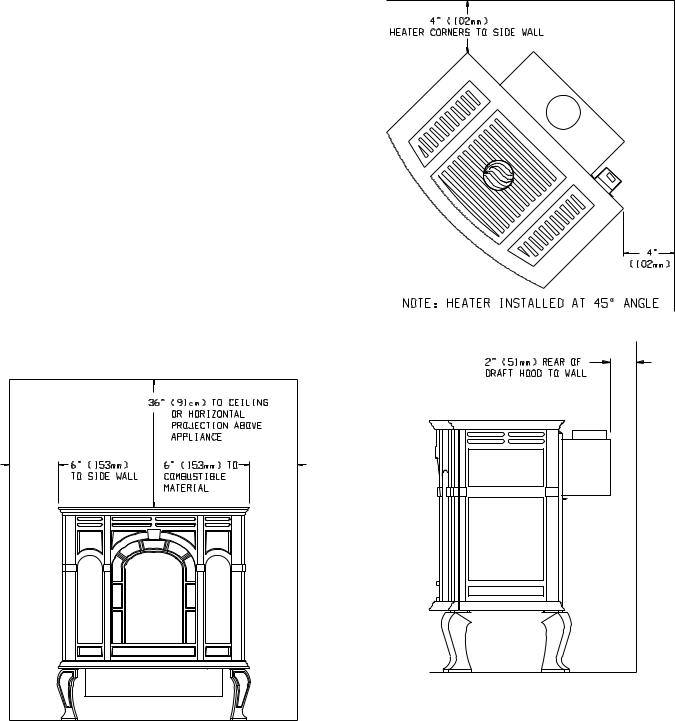
Locating and Venting the Fireplace Heater (Figures 1, 2 and 3)
Clearances: When facing the front of the fireplace heater the minimum clearances to combustible construction (material) are the following:
Open in front to provide service, access, and clearance to construction.
Top of appliance (ceiling) |
36 |
(inches) |
Draft Diverter to Rear Wall |
2 |
(inches) |
Side Wall |
6 |
(inches) |
Heater Corners (45° angle) to Wall |
4 |
(inches) |
Floor |
0 |
(inches) |
Figure 1
Figure 2
Figure 3
Page 4 |
R-3450 |

Appliance Hardware Package Parts List
|
Part |
|
Part |
Quantity |
|
|
Description |
|
Number |
Supplied |
|
|
1/4-20 x 1" Phillips Head Bolt |
R-3188 |
4 |
|
|
|
|
|
|
|
|
|
1/4-20 x 3/8" Phillips Head Bolt |
R-3646 |
16 |
|
|
|
1/4-20 x 1/2" Leveling Bolt |
R-3747 |
4 |
|
|
|
No. 10 x 1/2" |
R-2737 |
6 |
|
|
|
Hex Washer Head Screw |
|
|
|
|
|
1/4-20 Washer Head Nut |
R-3185 |
4 |
|
|
|
Leg Pad "A" |
(see Figure 5) |
CI-008 |
2 |
|
|
Leg Pad "B" |
(see Figure 5) |
CI-009 |
2 |
|
|
1-1/4" x 1/2" Retaining Tab |
CI-007 |
4 |
|
|
|
(see Figure 8) |
|
|
|
|
|
1/4 x 9/32 Washer (Not Shown) |
R-1150 |
8 |
|
|
|
|
|
|
|
|
Appliance Hardware Package (Figure 4)
Figure 4
Assembly of Cast Iron (Outer Casing) Stove Casting (Figures 5, 6, 7, 8 and 9)
Attention: Included in the hardware package are (8) 1/4" inside diameter washers. A 1/4" washer may be used with a 1/4-20 x 3/8" bolt when assembling the stove casting parts. If a bolt hole is not tapped deep enough for a tight fit between stove casting parts, the 1/4" washer can be used as a shim to provide a tight fit.
The 1/4" washers are not required for assembly of the stove casting if all the bolt holes are tapped to a proper depth.
Additonal 1/4" washers are to be purchased locally.
1.Place porcelain casting pieces on a non-abrasive surface in order to protect the porcelain finish. The exterior of the porcelain casting pieces should be facing the non-abrasive surface.
2.The assembly of the casting is accomplished in 6 stages:
A.Attaching legs to the sides (Figure 5).
B.Attaching rear cover to sides (Figure 6).
C.Removing protective packaging from casing front and window (Figure 7).
D.Assembly of front by attaching retaining tabs and placing front on unit (Figure 8).
E.Inserting firebox into partially completed assembly (Figure 9).
F.Placing top on unit.
3.Refer to Figure 5, the leg pads will have the letter "A" and "B" stamped into the metal. Place leg pad "A" and leg pad "B" at the bottom of each casing side. Leg pad "A" attaches to the front of the casing side, right and to the rear of the casing side, left. Leg pad "B" attaches to the rear of the casing side, right and to the front of the casing side, left. Position the 3/4" flange on the leg pad against the
(2) locator dimples on the casing side. The 3/4" flange must be facing upward, toward the top louver openings on the casing side. Attach the two rear leg pads to the casing sides with (2) 3/8" bolts. Attach but do not completely tighten the two front leg pads to the casing sides with (2) 3/8" bolts. Attention: The front leg pads can be adjusted to provide a snug fit between the casing front and the casing sides.
4.Attach (4) leveling bolts to the bottom of the (4) legs.
5.Align the 3/8" hole at the top of the leg with the 3/8" hole in the leg pad. Attention: For proper positioning of the leg to the leg pad the
(2) 1-1/2" top edges of the leg must be placed flush and parallel to the (2) edges on the leg pad. Attach leg to leg pad by inserting (1) 1" bolt through the leg pad and into the leg, secure bolt with 1/4" nut.
6.Insert (2) 3/8" bolts into the (2) holes on the edges of the casing sides. The bolts should only be threaded half-way into the holes in order to allow for clearance when the casing back is attached to the casing sides.
7.Refer to Figure 6, the rear cover has (4) keyholes for attachment to the casing sides. Stand the casing sides on the floor with the (2) bolts attached half-way into the edges of the rear cover positioned at the rear. The large diameter holes in the keyholes of the rear cover will be toward the floor. Working with one casing side at a time, place the large diameter holes in the keyholes over and behind both of the bolts at the same time. Push downward on the rear cover to lock the keyholes into position behind the bolts. Finish tightening both bolts to secure rear cover to casing side. Repeat this procedure to secure rear cover to the second casing side.
R-3450 |
Page 5 |
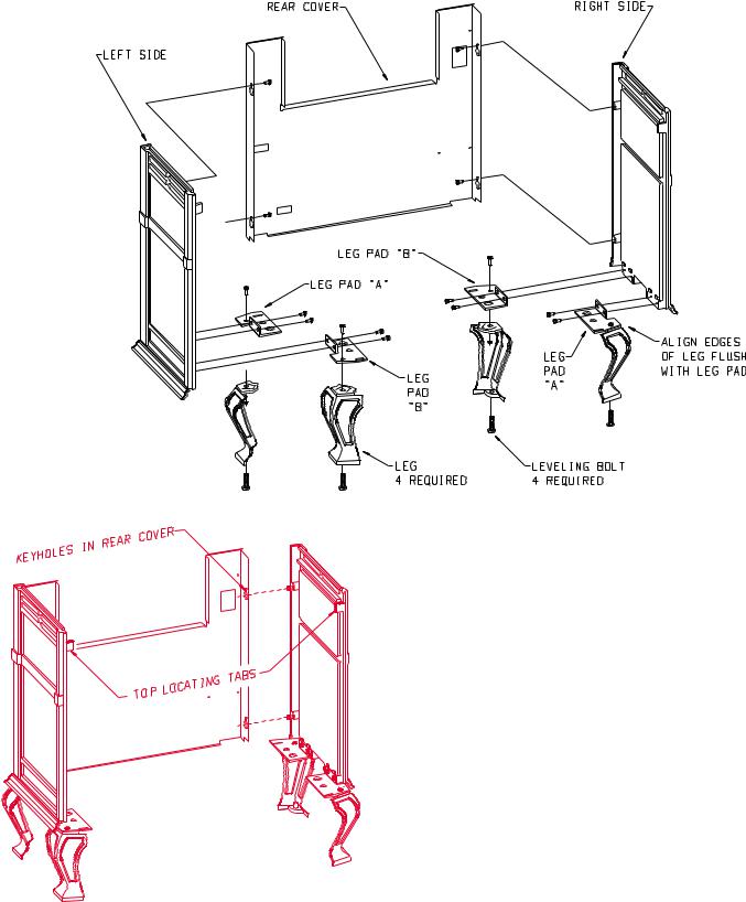
Figure 5
Figure 6
8.Position the completed portion of the casing in the approximate location for installation as the completed assembly will be heavy.
9.Refer to Figure 7, removing protective packing foam from casing front and window. Remove the (1) 3/4" bolt and (1) 1/4" washer from top of window. Remove (1) 3/8" bolt and 1 - 5/8" x 3/4" retaining tab from bottom of window. Remove the window from casing front. Remove the protective sheet of foam from the casing front.
Place the window into the casing front. Attach the top of the window to the casing front with (1) 1/4" washer and (1) 3/4" bolt. Place the 1 -5/8" x 3/4" retaining tab into the locator notch on the bottom of the casing front. Attach the bottom of the window to the casing front by inserting (1) 3/8" bolt through retaining tab and into locator notch.
10.Attach the (4) 1-1/4" x 1/2" retaining tabs to the casing front with (4) 3/8" bolts. The retaining tabs should be positioned downward, from the casing front, top to the casing front, bottom.
11.Refer to Figure 8, attach casing front to outer casing by using the
(4) retaining tabs on the casing front. The (2) top, retaining tabs on the casing front will be placed behind the (2) top, locator tabs on the front of the casing sides. The (2) bottom, retaining tabs will be inserted into the (2) 9/16" slots on the front, leg pads. Place the top, retaining tabs behind the top, locator tabs as you pivot inward the bottom of the casing front in order to insert the bottom, retaining tabs into the slots.
12.The following procedure will provide a snug fit between the casing front and the casing sides. Grasp the right, front leg, push inward on the leg in order to provide a snug fit between the casing front and the casing side. Continue to hold the right, front leg as you completely tighten the (2) 3/8" bolts that attach the leg pad to the right, casing side. Repeat procedure for left, front leg to achieve a snug fit between the casing front and the casing side.
13.Remove the casing front from the outer casing.
Page 6 |
R-3450 |

Figure 7
17. Insert center grille, left grille and right grille into casing top. 18. Level appliance by adjusting leveling bolts.
19. Assembly of cast iron (outer casing) stove casting is completed.
Figure 8
14.Refer to Figure 9, the appliance firebox can now be inserted into the outer casing. Center the firebox in the outer casing. Attention:
|
Remove (1) Phillips-head screw in the top of the valve cover. The |
Figure 9 |
|
screw is used to secure the valve cover in place during shipping. |
|
|
The (1) Phillips-head screw can be discarded. |
|
15. |
Attach casing front to outer casing as described in Step 11. |
|
16. |
Place the casing top onto the outer casing. The casing top nests into |
|
|
the outer casing. |
|
R-3450 |
Page 7 |
 Loading...