


INSTALLATION INSTRUCTIONS
AND
OWNER'S MANUAL
The Classic Cast Iron Stoves
CAST IRON
VENTED FIREPLACE HEATER
MODEL
CIBV-30-20
EFFECTIVE DATE
AUGUST 2006
Installer: Leave this manual with the appliance.
Consumer:Retain this manual for future reference.
WARNING: If the information in these instructions are not followed exactly, a fire or explosion may result causing property damage, personal injury or loss of life.
—Do not store or use gasoline or other flammable vapors and liquids in the vicinity of this or any other appliance.
—WHAT TO DO IF YOU SMELL GAS
•Do not try to light any appliance.
•Do not touch any electrical switch; do not use any phone in your building.
•Immediately call your gas supplier from a neighbor’s phone. Follow the gas supplier’s instructions.
•If you cannot reach your gas supplier, call the fire department.
—Installation and service must be performed by a qualified installer, service agency or the gas supplier.
AVERTISSEMENT: Assurez vous de bien suivre les instructions données dans cette notice pour réduire au minimum le risque d’incendie ou d’explosion ou pour éviter tout dommage matériel, toute blessure ou la mort.
—Ne pas entreposer ni utiliser d’essence ni d’autres vapeurs ou liquides inflammables dans le voisnage de cet appareil ou de tout autre appareil.
—QUEFAIRESIVOUSSENTEZUNEODEUR DE GAZ:
•Ne pas tenter d’allumer d’appareil.
•Ne touchez a aucun interrupteur. Ne pas vous servir des téléphones se trouvant dans le bâtiment où vous vous trouvez.
•Appelez immédiatement votre fournisseur de gaz depuis un voisin. Suivez les instructions du fournisseur.
•Si vous ne pouvez rejoindre le fournisseur de gaz, appelez le service des incendies.
—L’installation et l’entretien doivent être assurés par un installateur ou un service d’entretien qualifié ou par le fournisseur de gaz.
15627-4-0806 |
Page 1 |

TABLE OF CONTENTS |
|
SECTION |
PAGE |
Important Safety Information................................................................................................. |
3 |
Safety Information for Users of LP Gas................................................................................. |
4 |
Introduction............................................................................................................................ |
5 |
Specifications ......................................................................................................................... |
6 |
Gas Supply ............................................................................................................................. |
7 |
Clearances ............................................................................................................................. |
8 |
Appliance Hardware Package ................................................................................................ |
9 |
Assembly of Stove Casting .............................................................................................. |
9-12 |
Optional Stone Inlay Installation.......................................................................................... |
12 |
Wire Channel Installation..................................................................................................... |
13 |
Log Placement...................................................................................................................... |
13 |
Operating Guidelines............................................................................................................ |
14 |
Vent Safety Shutoff System.................................................................................................. |
14 |
Venting ................................................................................................................................. |
15 |
Lighting Instructions ........................................................................................................... |
16 |
Pilot Flame Characteristics................................................................................................... |
17 |
Main Burner Flame Characteristics...................................................................................... |
17 |
Wiring ............................................................................................................................ |
18-19 |
Maintenance ................................................................................................................... |
19-20 |
Troubleshooting................................................................................................................... |
21 |
How To Order Repair Parts.................................................................................................. |
22 |
Parts List for CIBV-30-20 ................................................................................................... |
22 |
Parts View for CIBV-30-20 ................................................................................................ |
23 |
Parts List for Stove Casting.................................................................................................. |
24 |
Parts View for Stove Casting................................................................................................ |
25 |
Optional Blower Installation Instructions ..................................................................... |
26-27 |
Page 2 |
15627-4-0806 |

IMPORTANT SAFETY INFORMATION
THIS IS A HEATING APPLIANCE
DO NOT OPERATE THIS APPLIANCE WITHOUT FRONT PANEL INSTALLED.
•Due to high temperatures, the fireplace heater should be locatedoutoftrafficandawayfromfurnitureanddraperies.
•Children and adults should be alerted to the hazards of high surface temperature and should stay away to avoid burns or clothing ignition.
•Young children should be carefully supervised when they are in the same room as the fireplace heater.
•Clothingorotherflammablematerialshouldnotbeplaced on or near the fireplace heater.
•Surveiller les enfants. Garder les vêtements, les meubles, l'essence ou autres liquides à vapeur inflammables lin de l'appareil.
•Due to high surface temperatures, keep children, clothing and furniture away.
•The glass front or any part removed for servicing the appliancemustbereplacedpriortooperatingtheappliance. Work should be done by a qualified service person.
•Keep burner and control compartment clean.
•Installation and repair should be done by a QUALIFIED SERVICE PERSON. The fireplace heater should be inspected before use and at least annually by a qualified service person. More frequent cleaning may be required due to excessive lint from carpeting, bedding material, etc. It is imperative that control compartments, burners and circulating air passageways of the fireplace heater be kept clean.
•S'assurerque le brûleuret le compartiment des commandes sont propres. Voir les instructions d'installation et d'utilisation qui accompagnent l'appareil.
•DO keep the appliance area clear and free from combustible material, gasoline and other flammable vapors and liquids.
•DOexamineburnersperiodically.Cleanandreplacedamaged parts.
•CAUTION: The glass used in your heater is a special high temperature ceramic glass. If the glass is cracked or damaged in any way, it should be replaced only with a complete glass frame assembly from Empire. See parts list on Page 22 for ordering.
•DO NOTuse this heaterif any part has been underwater. Immediately call a qualified service technician to inspect the heater and to replace any part of the control system and any gas control which has been under water.
•Ne pas se servirde cet appareil s'il a été plongé dans l'eau, complètementouenpartie.Appeleruntechnicienqualifié pour inspecter l'appareil et remplacer toute partie du systèmedecontrôleettoutecommandequiontétéplongés dans l'eau.
•Under no circumstances should any solid fuels (wood, coal, paper or cardboard etc.) be used in this appliance.
•WARNING: Any change to this fireplace heater or its controls can be dangerous. Any safety screen or guard removedforservicingafireplaceheatermustbereplaced prior to operating the fireplace heater
•WARNING: If not installed, operated and maintained in accordance with the manufacturer's instructions, this productcouldexposeyoutosubstancesinfuelorfromfuel combustion which can cause death or serious illness.
•WARNING: Do not operate appliance with the glass front removed, cracked or broken. Replacement of the glass should be done by a licensed or qualified service person.
15627-4-0806 |
Page 3 |

SAFETY INFORMATION FOR USERS OF LP-GAS
Propane (LP-Gas) is a flammable gas which can cause fires and explosions. In its natural state, propane is odorless and colorless.Youmaynotknowallthefollowingsafetyprecautions which can protect both you and yourfamily from an accident. Read them carefully now, then review them point by point
with the members of your household. Someday when there may not be a minute to lose, everyone's safety will depend on knowing exactly what to do. If, after reading the following information, you feel you still need more information, please contact your gas supplier.
LP-GAS WARNING ODOR
If a gas leak happens, you should be able to smell the gas because of the odorant put in the LP-Gas. That's your signal to go into immediate action!
•Do not operate electric switches, light matches, use your phone. Do not do anything that could ignite the gas.
•Get everyone out of the building, vehicle, trailer, or area. Do that IMMEDIATELY.
•Close all gas tank or cylinder supply valves.
•LP-Gas is heavier than air and may settle in low areas such as basements. When you have reason to suspect a gas leak, keep out of basements and other low areas. Stay out until firefighters declare them to be safe.
•Useyourneighbor'sphoneandcallatrainedLP-Gasservice person and the fire department. Even though you may not continue to smell gas, do not turn on the gas again. Do not re-enter the building, vehicle, trailer, or area.
•Finally,lettheservicemanandfirefighterscheckforescaped gas. Have them air out the area before you return. Properly trained LP-Gas service people should repair the leak, then check and relight the gas appliance for you.
NO ODOR DETECTED - ODOR FADE
Some people cannot smell well. Some people cannot smell the odor of the chemical put into the gas.You must find out if you can smell the odorant in propane. Smoking can decrease your ability to smell. Being around an odor for a time can affect your sensitivity or ability to detect that odor. Sometimes other odors in the area mask the gas odor. People may not smell the gas odor or their minds are on something else. Thinking about smelling a gas odor can make it easier to smell.
The odorant in LP-gas is colorless, and it can fade undersome circumstances. For example, if there is an underground leak, the movement of the gas through soil can filter the odorant. Odorants in LP-Gas also are subject to oxidation. This fading can occur if
there is rust inside the storage tank or in iron gas pipes.
Theodorantinescapedgascanadsorborabsorbontoorintowalls, masonry and other materials and fabrics in a room. That will take some of the odorant out of the gas, reducing its odor intensity.
LP-Gas may stratify in a closed area, and the odor intensity could vary at different levels. Since it is heavier than air, there may be more odor at lower levels.Always be sensitive to the slightest gas odor. If you detect any odor, treat it as a serious leak. Immediately go into action as instructed earlier.
SOME POINTS TO REMEMBER
•Learn to recognize the odor of LP-gas. Your local LP-Gas Dealer can give you a "Scratch and Sniff" pamphlet. Use it to find out what the propane odor smells like. If you suspect that your LP-Gas has a weak or abnormal odor, call your LP-Gas Dealer.
•If you are not qualified, do not light pilot lights, perform service, or make adjustments to appliances on the LP-Gas system.Ifyouarequalified,consciouslythinkabouttheodor of LP-Gas prior to and while lighting pilot lights or performing service or making adjustments.
•Sometimes a basement or a closed-up house has a musty smell that can cover up the LP-Gas odor. Do not try to light pilot lights, perform service, or make adjustments in an area where the conditions are such that you may not detect the odor if there has been a leak of LP-Gas.
•Odor fade, due to oxidation by rust or adsorption on walls of new cylinders and tanks, is possible. Therefore, people should be particularly alert and careful when new tanks or cylinders are placed in service. Odor fade can occur in new tanks, or reinstalled old tanks, if they are filled and allowed to set too long before refilling. Cylinders and tanks which
have been out of service for a time may develop internal rust which will cause odor fade. If such conditions are suspected to exist, a periodic sniff test of the gas is advisable. If you have any question about the gas odor, call your LP-gas dealer.Aperiodic sniff test of the LP-gas is a good safety measure under any condition.
•If, at any time, you do not smell the LP-Gas odorant and you thinkyoushould,assumeyouhavealeak.Thentakethesame immediateactionrecommendedabovefortheoccasionwhen you do detect the odorized LP-Gas.
•If you experience a complete "gas out," (the container is under no vapor pressure), turn the tank valve off immediately. If the container valve is left on, the container may draw in some air through openings such as pilot light orifices. If this occurs, some new internal rusting could occur. If the valve is left open, then treat the container as a new tank. Always be sure your container is under vapor pressure by turning it off at the container before it goes completely empty or having it refilled before it is completely empty.
Page 4 |
15627-4-0806 |

INTRODUCTION
Introduction
Always consult your local Building Department regarding regulations, codes or ordinances which apply to the installation of a vented fireplace heater.
Instructions to Installer
1.Installer must leave instruction manual with owner after installation.
2.Installer must have owner fill out and mail warranty card supplied with heater.
3.Installer should show owner how to start and operate heater and thermostat.
General Information
This appliance is design certified in accordance with American NationalStandard/CSAStandardANSI Z21.88andCSA2.33by theCanadianStandardsAssociation,asaVentedFireplaceHeater and must be installed according to these instructions.
Any alteration of the original design, installed other than as shown in these instructions or use with a type of gas not shown on the rating plate is the responsibility of the person and company making the change.
Important
All correspondence should refer to complete Model Number, Serial Number and type of gas.
Notice: During initial firing of this unit, its paint will bake out and smoke will occur. To prevent triggering of smoke alarms, ventilate the room in which the unit is installed.
Qualified Installing Agency
Installation and replacement of gas piping, gas utilization equipment or accessories and repair and servicing of equipment shallbeperformedonlybyaqualifiedagency.Theterm"qualified agency" means any individual, firm, corporation or company which either in person or through a representative is engaged in and is responsible for (a) the installation or replacement of gas piping or (b) the connection, installation, repair or servicing of equipment, who is experienced in such work, familiar with all precautions required and has complied with all the requirements of the authority having jurisdiction.
State of Massachusetts: The installation must be made by a licensed plumber or gas fitter in the Commonwealth of Massachusetts.
The installation must conform with local codes or, in the absence of local codes, with the National Fuel Gas Code, ANSI Z223.1/ NFPA 54.*
*Available from the American National Standards Institute, Inc., 11 West 42nd St., New York, N.Y. 10036.
High Altitudes
When installing this unit at an elevation above 2000 feet (in the United States) it may be necessary to decrease the input rating by changing the existing burner orifice to a smaller size. Generally, input should be reduced 4 percent for each 1000 feet above sea level. However, if the heating value of the gas has been reduced, this general rule may not apply. Check with local gas utility for proper orifice size identification.
APPLIESTOCANADIANMODELSONLYFORPROPANE GAS.
Altitude: 0-4,500 feet (0-1370 m) without orifice change.
APPLIESTOCANADIANMODELSONLYFORNATURAL GAS.
Altitude 0-2,000 feet (0-610m) without orifice change.
Cet appareil est équipé pour des altitudes compris entre 0 et 2000 pieds (0-610m) seulement.
For installations from 610-1370 metres (2,000-4,500 ft.) the orifice size (DMS) for natural gas is 39. See data plate for additional information.
For high altitude installations consult the local gas distributor or the authority having jurisdiction for proper rating methods. If the installer must convert the unit to adjust for varying altitudes, the information sticker (illustrated below) must be filled out by the installer and adhered to the appliance at the time of conversion.
THE CONVERSION SHALL BE CARRIED OUT BYAMANUFACTURER'S AUTHORIZED REPRESENTATIVE IN ACCORDANCE WITH THE REQUIREMENTS OF THE MANUFACTURER,PROVINCIALORTERRITORIALAUTHORITIES HAVINGJURISDICTIONANDINACCORDANCEWITHTHE REQUIREMENTSOFTHECAN/CGA-B141.1ORCAN/CGA- B141.2 INSTALLATION CODES.
LA CONVERSION DOIT ÊTRE EFFECTUÉE CONFORMÉMENT AUX RÉGLEMENTATION PROVINCIAUX EN CAUSEETAUXEXIGENCESDESCODESD'INSTALLATION CAN/CGA-B149.
This appliance has been converted for use at an altitude of
Orifice size |
|
|
|
|
Manifold Pressure |
|
||
Input (Btu/h) |
|
|
|
Fuel Type |
|
|
|
|
Date of Conversion |
|
|
Converted by |
|
|
|||
Cet appareil a été converti au
Injecteur Pression à la tubulure d'alimentation Déoit calorifique
15627-4-0806 |
Page 5 |

SPECIFICATIONS |
|
|
|
Model |
CIBV-30 |
Input BTU/HR (KW/H) Maximum |
30,000 (8.7) |
BTU/HR (KW/H) Minimum |
21,000 (6.2) |
Height |
27 3/4" (704mm) |
Width |
25 `/1" (647mm) |
Depth including diverter |
21" (533mm) |
Gas Inlet |
1/2" (13mm) |
Size Draft Diverter Collar |
4" (101mm) |
Floor to top of collar on vertical position of Draft Diverter |
27 3/8" (695mm) |
Floor to center of collar on horizontal position of Draft |
23 1/2" (596mm) |
Diverter |
|
Stove Casting (Must be ordered with Firebox) |
|
CIFB-1 |
Flat Black |
CIPB-1 |
Porcelain Black |
CIPG-1 |
Porcelain Green |
CIPS-1 |
Porcelain Sand |
CIPN-1 |
Porcelain Navy |
CIPR-1 |
Porcelain Red |
Accessories |
|
TMV |
Millivolt Wall Thermostat - Reed Switch |
FRBC-1 |
Battery Operated Remote Control |
FRBTC-1 |
Battery Operated Remote Control w/Thermostat |
FREC-1 |
Electric Remote Control |
FWS-1 |
Wall Switch |
CIB-2 |
Automatic Blower |
Stone Inlay Replaces Standard Grill Top
CII-2 |
Stone Inlay |
Empress Green |
CII-3 |
Stone Inlay |
Hunan Jade |
CII-4 |
Stone Inlay |
Gray Botticino |
CII-5 |
Stone Inlay |
Azul |
CII-6 |
Stone Inlay |
Salome |
CII-7 |
Stone Inlay |
Black Swan |
Page 6 |
15627-0-0903 |

GAS SUPPLY
Consult the current National Fuel Gas Code,ANSI Z223.1 CAN/ CGA-B149 (.1 or .2) installation code.
Recommended Gas Pipe Diameter
Pipe Length |
Schedule 40 Pipe |
Tubing, Type L |
||
|
Inside Diameter |
Outside Diameter |
||
|
Nat. |
L.P. |
Nat. |
L.P. |
0-10 feet |
1/2” |
3/8” |
1/2” |
3/8” |
0-3 meters |
12.7mm |
9.5mm |
12.7mm |
9.5mm |
10-40 feet |
1/2” |
1/2” |
5/8” |
1/2” |
4-12 meters |
12.7mm |
12.7mm |
15.9mm |
12.7mm |
40-100 feet |
1/2” |
1/2” |
3/4” |
1/2” |
13-30 meters |
12.7mm |
12.7mm |
19mm |
12.7mm |
100-150 feet |
3/4” |
1/2” |
7/8” |
3/4” |
31-46 meters |
19mm |
12.7mm |
22.2mm |
19mm |
Note:Neveruseplasticpipe.Checktoconfirmwhetheryourlocal codes allow copper tubing or galvanized.
Note: Since some municipalities have additional local codes, it is always best to consult your local authority and installation code.
The use of the following gas connectors is recommended:
—ANS Z21.24 Appliance Connectors of Corrugated Metal Tubing and Fittings
—ANS Z21.45 Assembled Flexible Appliance Connectors of Other Than All-Metal Construction
The above connectors may be used if acceptable by the authority having jurisdiction. The state of Massachusetts requires that a flexible appliance connector cannot exceed three feet in length.
Figure 1
Installing a New Main Gas Cock
Each appliance should have its own manual gas cock.
A manual main gas cock should be located in the vicinity of the unit. Where none exists, or where its size or location is not adequate, contact your local authorized installer for installation or relocation.
Compoundsusedonthreadedjointsofgaspipingshallberesistant to the action of liquefied petroleum gases. The gas lines must be checked for leaks by the installer.This should be done with a soap solution watching for bubbles on all exposed connections, and if unexposed, a pressure test should be made.
Neveruseanexposedflametocheckforleaks.Appliancemust be disconnected from piping at inlet of control valve and pipe capped or plugged for pressure test. Never pressure test with appliance connected; control valve will sustain damage!
NOTE: The gas control is equipped with a captured screw type pressure test point, therefore it is not necessary to provide a 1/8" test point up stream of the control.
A gas valve and ground joint union should be installed in the gas line upstream of the gas control to aid in servicing. It is required by the National Fuel Gas Code that a drip line be installed near the gas inlet. This should consist of a vertical length of pipe tee connected into the gas line that is capped on the bottom in which condensation and foreign particles may collect.
When using copper or flex connector use only approved fittings. Alwaysprovideaunionsothatgaslinecanbeeasilydisconnected for burner servicing.
Theapplianceandit'sindividualshutoffvalvemustbedisconnected from supply piping system during any pressure testing of that system at test pressures in excess of 1/2 psig (3.5kPa).
The appliance must be isolated from the gas supply piping system byclosingitsindividualmanualshutoffvalveduringanypressure testing of the gas supply piping system at test pressures equal to or less than 1/2 psig (3.5kPa).
Attention! If one of the procedures results in pressures in excess of 1/2 psig (14" w.c.) (3.5 kPa) on the fireplace gas valve, it will result in a hazardous condition.
Checking Manifold Pressure
Both Propane and Natural gas valves have a built-in pressure regulatorinthegasvalve. Naturalgasmodelswillhaveamanifold pressureofapproximately3.5"w.c.(.871kPa)formaximuminput or 1.7" w.c. (.423kPa) for minimum input at the valve outlet with the inlet pressure to the valve from a minimum of 5.0" w.c. (1.245kPa) for the purpose of input adjustment to a maximum of 10.5" (2.615kPa) w.c. Propane gas models will have a manifold pressure approximately 10.0"w.c. (2.49kPa) for maximum input or 5.9" w.c. (1.469kPa) for minimum input at the valve outlet with the inlet pressure to the valve from a minimum of 11.0" w.c. (2.739kPa) for the purpose of input adjustment to a maximum of 13.0" w.c. (3.237kPa).
A 1/8" (3mm) N.P.T. plugged tapping, accessible for test gauge connection, is located on the outlet side of the gas control.
15627-0-0903 |
Page 7 |
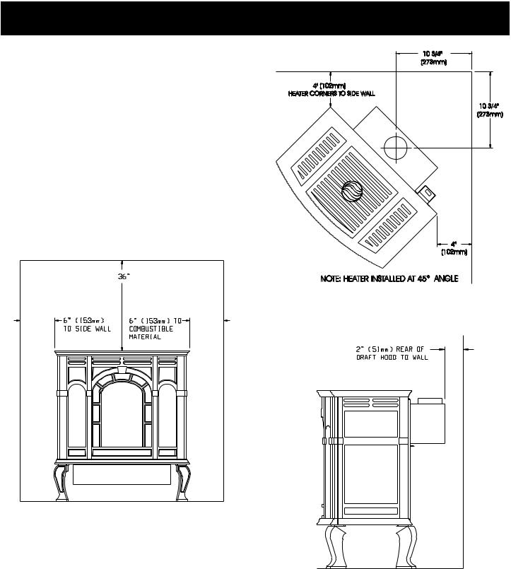
CLEARANCES
Clearances: When facing the front of the fireplace heater the minimum clearances to combustible construction (material) are the following:
Open in front to provide service, access, and clearance to construction.
Top of appliance (ceiling) |
36 |
(inches) |
Draft Diverter to Rear Wall |
2 |
(inches) |
Side Wall |
6 |
(inches) |
Heater Corners (45° angle) to Wall |
4 |
(inches) |
Floor |
0 |
(inches) |
Installation on Rugs and Tile
If this appliance is to be installed directly on carpeting, tile, or other combustible material, other than wood flooring, the appliance shall be installed on a metal or wood panel extending the full width and depth of the appliance.
The base referred to above does not mean the fire-proof base as usedonwoodstoves.Theprotectionisprimarilyforrugsthatmay be extremely thick and light-color tile that can discolor.
(914mm) TO CEILING OR HORIZONTAL PROJECTION ABOVE APPLIANCE
Figure 3
Figure 2
Figure 4
Page 8 |
15627-4-0806 |
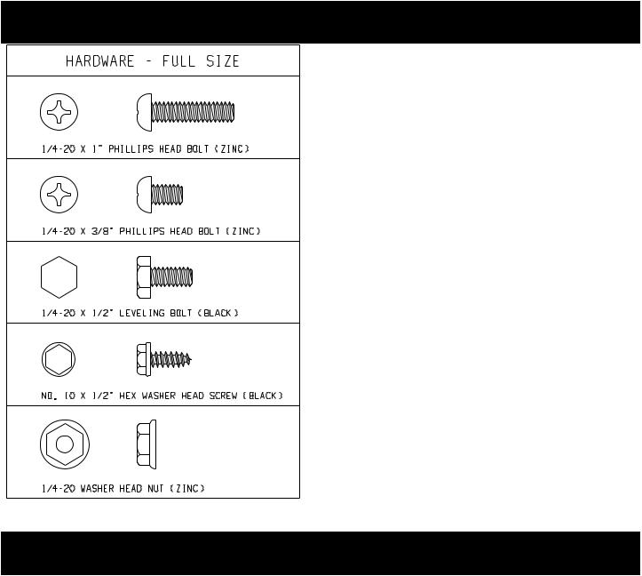
APPLIANCE HARDWARE PACKAGE
Appliance Hardware Package Parts List
Part |
Part |
Quantity |
Description |
Number |
Supplied |
1/42-0 x 1" Phillips Head Bolt |
R-3188 |
4 |
1/4-20 x 3/8" Phillips Head Bolt |
R-3646 |
16 |
1/4-20 x 1/2" Leveling Bolt |
R-3747 |
4 |
No. 10 x 1/2" Hex Washer Head Screw |
R-2737 |
10 |
1/4-20 Washer Head Nut |
R-3185 |
4 |
Leg Pad "A" (see Figure 6) |
CI-008 |
2 |
Leg Pad "B" (see Figure 6) |
CI-009 |
2 |
1-1/4" x 1/2" Retaining Tab (see Figure 8) |
CI-007 |
4 |
1/4" x 9/32 Washer (Not Shown) |
R-1150 |
8 |
Figure 5
ASSEMBLY OF STOVE CASTING
Assembly of Stove Casting (Figures 6, 7, 8, 9, 10, 11 and 12) Attention: Included in the hardware package are (8) 1/4" inside diameterwashers.A1/4"washermaybeusedwitha1/4-20x3/8" bolt when assembling the stove casting parts. If a bolt hole is not tapped deep enough for a tight fit between stove casting parts, the 1/4" washer can be used as a shim to provide a tight fit.
The1/4"washersarenotrequiredforassemblyofthestovecasting if all the bolt holes are tapped to a proper depth.
Additonal 1/4" washers are to be purchased locally.
1.Place porcelain casting pieces on a non-abrasive surface in order to protect the porcelain finish. The exterior of the porcelain casting pieces should be facing the non-abrasive surface.
2.The assembly of the casting is accomplished in 7 stages:
A.Attaching legs to the sides (Figure 6).
B.Attaching rear cover to sides (Figure 7).
C.Removing protective packaging from casting front and window (Figure 8).
D.Assembly of front by attaching retaining tabs and placing front on unit (Figure 9).
E.Insertingfireboxintopartiallycompletedassembly(Figure 10 and Figure 11).
F.Attaching firebox to rear cover (Figure 12).
G.Placing top on unit.
Detailed Instructions Follow
3.Refer to Figure 6, the leg pads will have the letter "A" and "B" stamped into the metal. Place leg pad "A" and leg pad "B" at the bottom of each casting side. Leg pad "A" attaches to the front of the casting side, right and to the rear of the castingside,left.Legpad"B"attachestotherearofthecasting side, right and to the front of the casting side, left. Position the 3/4" flange on the leg pad against the (2) locator dimples on the casting side. The 3/4" flange must be facing upward, toward the top louver openings on the casting side. Attach the two rear leg pads to the casting sides with (2) 3/8" bolts. Attach but do not completely tighten the two front leg pads to the casting sides with (2) 3/8" bolts. Attention: The front leg pads can be adjusted to provide a snug fit between the casting front and the casting sides.
4.Attach (4) leveling bolts to the bottom of the (4) legs.
15627-4-0806 |
Page 9 |
 Loading...