


Copeland Scroll® Compressor Module
Installation, Operation & Maintenance Manual
Model Family
SZV32
SZV44
SZO44
SZO56
Dual-Compressor Module TABLE OF CONTENTS
TABLE OF CONTENTS
Compressor Module Nomenclature............................................................................................. |
iv |
||
Important Safety Information........................................................................................................ |
1 |
||
1.0 |
Introduction....................................................................................................................... |
3 |
|
1.1 |
The Compressor Module............................................................................................................... |
3 |
|
1.2 |
The Compressor............................................................................................................................ |
4 |
|
1.3 |
The Compressor Package............................................................................................................. |
4 |
|
2.0 |
Installation........................................................................................................................ |
5 |
|
2.1 |
Installation Guidelines................................................................................................................... |
5 |
|
|
2.1.1 Required Component—Inlet Gas Scrubber..................................................................................... |
5 |
|
|
2.1.2 |
General Installation Guidelines........................................................................................................ |
5 |
2.2 |
Inlet and Discharge Pressures...................................................................................................... |
5 |
|
2.3 |
Ambient Temperature Range........................................................................................................ |
6 |
|
2.4 |
Installation Clearance and Dimensions......................................................................................... |
7 |
|
2.5 |
Process and Instrumentation Diagrams (P&IDs)........................................................................... |
8 |
|
2.6 |
Electrical Controls......................................................................................................................... |
9 |
|
|
2.6.1 |
General Considerations................................................................................................................... |
9 |
|
2.6.2 Oil Cooler Fan Control................................................................................................................... |
10 |
|
|
2.6.3 Compressor Module Motor Protection........................................................................................... |
12 |
|
|
2.6.4 |
Electrical Requirements................................................................................................................. |
13 |
|
2.6.5 |
Wiring............................................................................................................................................. |
14 |
|
2.6.6 Variable Frequency Drive (VFD) Terminations............................................................................... |
15 |
|
3.0 |
Operation......................................................................................................................... |
17 |
|
3.1 |
Initial Startup - Compressor Module............................................................................................ |
17 |
|
|
3.1.1 |
Pre-Startup Checklist..................................................................................................................... |
17 |
|
3.1.2 |
Post-Startup Checklist.................................................................................................................... |
17 |
3.2 |
Initial Startup - Compressor Package.......................................................................................... |
18 |
|
3.3 |
Normal Operation Checklist........................................................................................................ |
18 |
|
4.0 |
Maintenance..................................................................................................................... |
19 |
|
4.1 |
Routine Maintenance.................................................................................................................. |
19 |
|
i |
2006SSD-75 R4 (10/10) |
Dual-Compressor Module |
TABLE OF CONTENTS |
|
4.2 |
Maintenance Tools...................................................................................................................... |
20 |
4.3 |
Checking the Oil Level................................................................................................................ |
21 |
|
4.3.1 Oil Level Guidelines - Minimum Speed.......................................................................................... |
21 |
|
4.3.2 Oil Level Guidelines - Maximum Speed......................................................................................... |
21 |
4.4 |
Oil Capacity and Type................................................................................................................. |
21 |
4.5 |
Adding and Removing Oil............................................................................................................ |
22 |
|
4.5.1 Topping Off the Oil Level................................................................................................................ |
22 |
|
4.5.2 Changing the Oil............................................................................................................................ |
23 |
4.6 |
Cleaning the Inlet Screen............................................................................................................ |
25 |
4.7 |
Servicing the Scavenge Line Orifice........................................................................................... |
25 |
4.8 |
Changing the Second-Stage Separator Element........................................................................ |
26 |
4.9 |
Changing the Oil Filter Element.................................................................................................. |
26 |
5.0 |
Troubleshooting.............................................................................................................. |
27 |
5.1 |
Troubleshooting Guide................................................................................................................ |
27 |
5.2 |
Motor Winding Resistance.......................................................................................................... |
27 |
5.3 |
Platform Symptoms Diagnosis.................................................................................................... |
28 |
6.0 |
Specifications................................................................................................................... |
29 |
Appendix A Material Data Safety Sheet.................................................................................... |
32 |
|
A.1 |
Supplier....................................................................................................................................... |
32 |
A.2 |
Product Name and Information................................................................................................... |
32 |
A.3 |
Components and Hazard Statement........................................................................................... |
32 |
A.4 |
Safe Handling and Storage......................................................................................................... |
32 |
A.5 |
Physical Data.............................................................................................................................. |
32 |
A.6 |
Fire and Explosion Hazards........................................................................................................ |
33 |
A.7 |
Reactivity Data............................................................................................................................ |
33 |
A.8 |
Health Hazard Data..................................................................................................................... |
33 |
A.9 |
Personal Protection Information.................................................................................................. |
33 |
A.10 |
Spill or Leak Procedures............................................................................................................. |
33 |
A.11 |
Waste Disposal Methods............................................................................................................. |
33 |
ii |
2006SSD-75 R4 (10/10) |
Dual-Compressor Module |
TABLE OF CONTENTS |
|
|
FIGURES |
|
Figure 1 |
Compressor Module Components ......................................................................................................... |
3 |
Figure 2 |
Copeland Scroll® Compressor Cross Section......................................................................................... |
4 |
Figure 3 |
Typical Compressor Package ................................................................................................................ |
4 |
Figure 4 |
Compressor Module Dimensions, in. (mm)............................................................................................ |
7 |
Figure 5 |
Compressor Module Gas and Oil Flow Diagram and Safety Shutdowns............................................... |
8 |
Figure 6 |
Brushless DC Fan ................................................................................................................................ |
10 |
Figure 7 |
Basic Fan Control System ................................................................................................................... |
10 |
Figure 8 |
Optional Customer-Installed High Temperature Fan Control System .................................................. |
11 |
Figure 9 |
Oil Cooling and Thermal Valve............................................................................................................. |
11 |
Figure 10 |
Motor Control ....................................................................................................................................... |
12 |
Figure 11 |
Typical Compressor Module Electrical Requirements.......................................................................... |
13 |
Figure 12 |
Control Circuit Terminations ................................................................................................................. |
14 |
Figure 13 |
Power Terminations ............................................................................................................................. |
14 |
Figure 14 |
Maintenance Tools................................................................................................................................ |
18 |
Figure 15 |
Adding or Draining Oil .......................................................................................................................... |
21 |
Figure 16 |
Gas Inlet Block and Screen ................................................................................................................. |
23 |
Figure 17 |
Scavenge Line Orifice .......................................................................................................................... |
23 |
Figure 18 |
Oil Filter Bowl and Element.................................................................................................................. |
24 |
|
TABLES |
|
Table 1 |
Inlet and discharge pressure limits......................................................................................................... |
5 |
Table 2 |
Typical Compressor Module power supply requirements..................................................................... |
13 |
Table 3 |
Maintenance summary......................................................................................................................... |
17 |
Table 4 |
Troubleshooting.................................................................................................................................... |
25 |
Table 5 |
Motor winding resistance...................................................................................................................... |
25 |
Table 6 |
Platform troubleshooting guidelines..................................................................................................... |
26 |
Table 7 |
Compressor Module specifications....................................................................................................... |
27 |
Table 8 |
Compressor Module flow, pressure and horsepower data (see Notes 1 - 3*)...................................... |
29 |
iii |
2006SSD-75 R4 (10/10) |
Dual-Compressor Module |
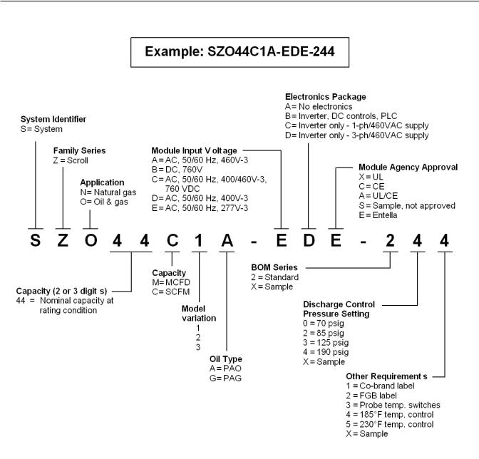
Compressor Module Nomenclature |
Compressor Module Nomenclature
|
|
|
|
|
|
|
Oil |
|
|
|
|
|
|
|
High |
|
|
Thermal |
|
|
|
|
Max |
|
|
Press |
Low |
|
Bypass |
|
|
|
|
Delivery |
Max |
|
Switch |
Press |
High Temp |
Valve |
|
Module |
|
|
Pressure |
Flow |
Drive |
Setting |
Switch |
Setting |
Setpoint |
Gas Bypass |
Weight |
|
Model |
(PSIG) |
(MCFD) |
HP |
(PSIG) |
Setting |
°F (°C) |
°F (°C) |
Valve |
(Lbs.) |
|
|
|
|
|
|
|
|
|
|
|
|
|
|
|
|
Dual Scroll Units |
|
|
|
|
||
SZO56C1A-EDE-110 |
150 |
260 |
30 |
215 |
0.75 PSIG |
240 (116) |
200 |
NO |
625 |
|
(52 mbarg) |
||||||||||
|
|
|
|
|
|
|
|
|
||
|
|
|
|
|
|
|
|
|
|
|
SZO44C1A-EDE-140 |
190 |
200 |
30 |
215 |
0.75 PSIG |
240 (116) |
200 |
NO |
625 |
|
(52 mbarg) |
||||||||||
|
|
|
|
|
|
|
|
|
||
|
|
|
|
|
|
|
|
|
|
|
SZO44C1A-EDE-244 |
190 |
200 |
30 |
215 |
0.75 PSIG |
240 (116) |
200 |
YES |
625 |
|
(52 mbarg) |
||||||||||
|
|
|
|
|
|
|
|
|
||
|
|
|
|
|
|
|
|
|
|
|
SZV44C1A-EDE-140 |
190 |
200 |
30 |
215 |
0.75 PSIG |
280 (138) |
250 |
NO |
625 |
|
(52 mbarg) |
||||||||||
|
|
|
|
|
|
|
|
|
||
|
|
|
|
|
|
|
|
|
|
|
SZV32C1A-EDE-150 |
275 |
150 |
30 |
290 |
0.75 PSIG |
280 (138) |
250 |
NO |
625 |
|
(52 mbarg) |
||||||||||
|
|
|
|
|
|
|
|
|
||
|
|
|
|
|
|
|
|
|
|
|
iv |
2006SSD-75 R4 (10/10) |
Dual-Compressor Module |
Important Safety Information |
Important Safety Information
This manual contains important instructions for installation, operation and maintenance of your Copeland Scroll® Compressor Module.
WARNING
The Compressor Module must be installed ONLY in systems that have been designed by qualified engineering personnel. The system must conform to all applicable local and national regulations and safety standards.
These instructions are intended to assist in the installation and operation of the Compressor Module and MUST be kept with the Compressor.
Service and maintenance of the Compressor Module must be performed by qualified technicians only. Service and maintenance must conform to all applicable local and national regulations and safety standards.
Thoroughly review this manual, all instructions and hazard warnings before performing any work on the Compressor Module.
Maintain all Compressor Module operation and hazard warning labels.
WARNING
Flammable gas can form explosive mixtures with air. Explosive gases can cause property damage, serious personal injury or death.
WARNING
Failure to disconnect and lockout electrical power from the Compressor Module before attempting maintenance can cause shock, burns, severe personal injury or death.
WARNING
Loosening or removing pressure-containing components from the Compressor Module when it is in operation can cause major property damage, serious personal injury or death.
Failure to relieve system pressure prior to performing service or maintenance on the Compressor Module can cause property damage or serious personal injury.
CAUTION
Extreme heat can cause personal injury or property damage.
CAUTION
Always use a lifting device capable of supporting the full weight of the Compressor Module or component being lifted.
Handling or lifting heavy assemblies can cause personal injury or property damage.
1 |
2006SSD-75 R4 (10/10) |

Dual-Compressor Module |
Important Safety Information |
|
|
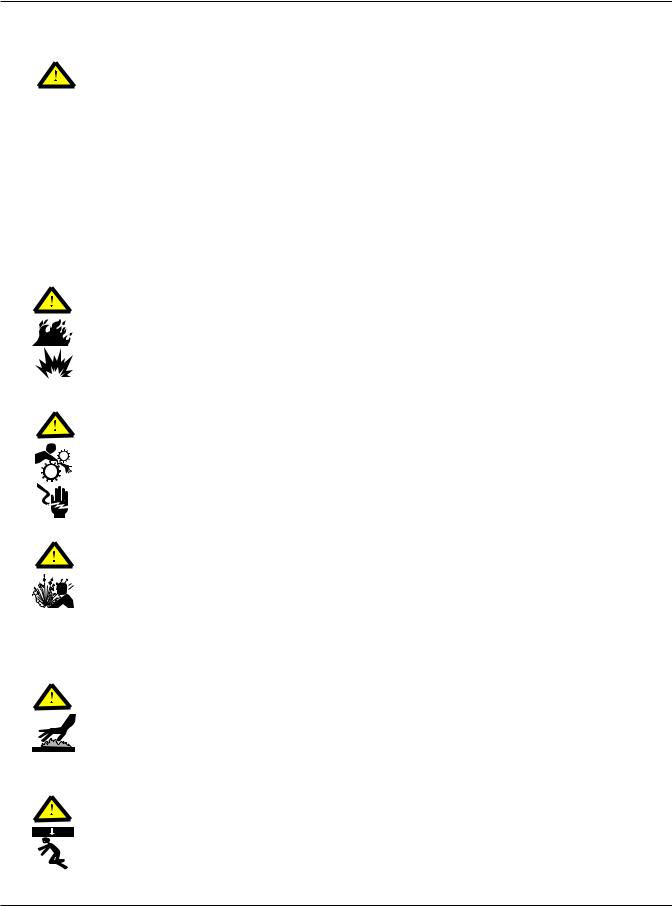
Safety Symbols Used in This Manual
SAFETY ALERT SYMBOL
When you see this symbol on the Compressor Module or in this manual, look for one of the following words and be aware of the potential for personal injury or property damage.
WARNING
A Warning describes hazards that CAN or WILL cause serious personal injury, death or major property damage.
CAUTION
A Caution describes hazards that CAN cause personal injury or property damage.
NOTE
A Note indicates special instructions that are very important and must be followed.
2 |
Form No. 2006SSD-75 (5/06) Rev. 0 |
Dual-Compressor Module |
Introduction |
1.0Introduction
The Copeland Scroll® SZO44 Compressor Module comes equipped with two Copeland Scroll® Compressors designed for Class I, Division II applications. The Compressor Module is designed for assembly into a Compressor Package ready for service in the field; the completed housing is done by equipment Packagers. This section provides an overview of these components.
These terms are used throughout this manual:
•Compressor Module - the SZO44 Compressor Module shown in Section 1.1
•Compressor - a Copeland Scroll® Compressor (two per Compressor Module)
•Compressor Package - the entire assembly, including the Compressor Module, ready for service in the field
•Packagers - the company that prepares the Compressor Module for service
•VFD - Variable Frequency Drive used to power a variable speed Compressor Module
1.1The Compressor Module
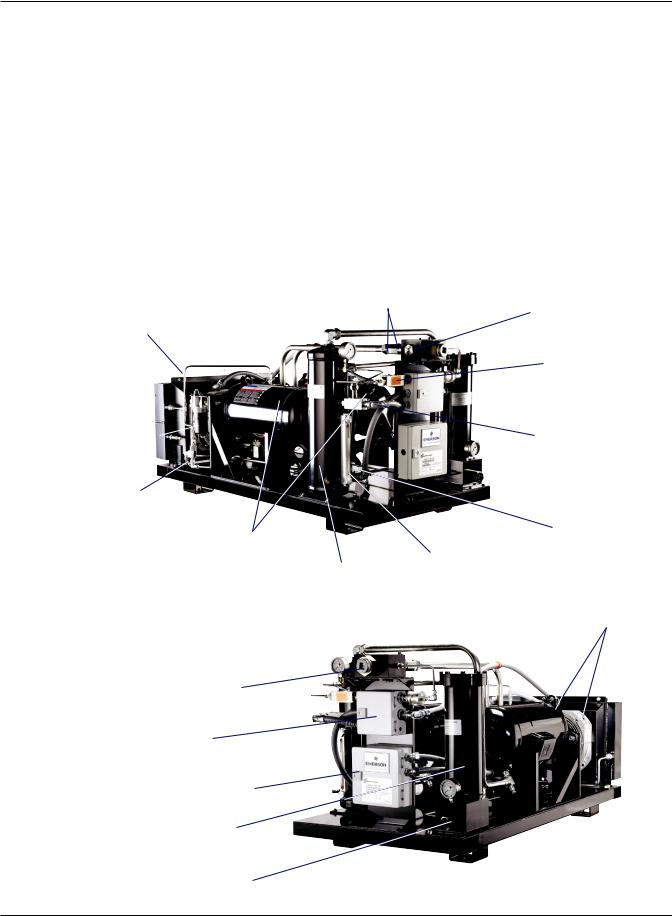
The Compressor Module consists of two Compressors and the other components shown in Figure 1.
Figure 1 Compressor Module Components
Oil coolers with fans (2)
LEFT
SIDE
VIEW
Oil circuit  filter
Oil circuit thermal bypass valve
Copeland Scroll® compressors (2) for Class I, Divison II
RIGHT
SIDE
VIEW
Suction gas connection (1-1/2" NPT)
Control wiring terminations
Power wiring terminations
Second-stage separator
Discharge gas connection (1" NPT)
Inlet check valves (2)
Oil level First-stage sight tube oil separator
Inlet suction screen
High discharge
gas pressure switch
High discharge gas temp switch
Fan speed thermistor
Oil cooler fans (2)
3 |
2006SSD-75 R4 (10/10) |
Dual-Compressor Module |
Introduction |
|
|
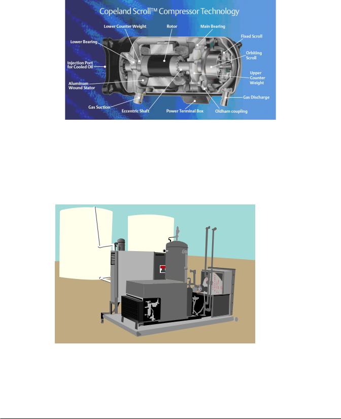
1.2The Compressor
The Compressor refers to the Copeland Scroll® Compressor. Each Compressor Module has two Compressors. Figure 2 shows a cross-section of a Compressor and its key components.
Figure 2 Copeland Scroll® Compressor Cross Section
1.3The Compressor Package
The Compressor Package consists of the Compressor Module housed in an assembly ready for service in the field. Equipment Packagers customize the assembly and complete the fabrication for Compressor Modules for each application. Figure 3 shows a simplified example of a Compressor Package.
Figure 3 Typical Compressor Package
Inlet gas scrubber for liquid removal
Control and power panel
Gas aftercooler (if applicable)
Oil cooler
Compressor
Module
4 |
Form No. 2006SSD-75 (5/06) Rev. 0 |
Dual-Compressor Module |
Installation |
2.0Installation
2.1Installation Guidelines
2.1.1Required Component—Inlet Gas Scrubber
An appropriate inlet gas scrubber is REQUIRED to remove liquids from the gas prior to compression. If there is potential for liquid slugging, a suitable trap must be installed to prevent liquid from flooding and damaging the Compressor.
NOTE
Failing to use an appropriate inlet gas scrubber to remove liquids from the gas prior to compression can cause flooding and damage the Compressor.
2.1.2General Installation Guidelines
Follow these general guidelines for installation:
•The Compressor Module must be installed and operated in compliance with all applicable codes and regulations.
•The system must be installed on a level surface.
•Install pipe unions or flanges to connect the system to the inlet and discharge piping for ease of service.
•Install isolation valves on the inlet and discharge piping.
•A common ground must be connected between the Compressor Module and the
Compressor Package chassis. This ground must comply with the National Electric Code (NEC) and any other applicable codes.
•Solid debris also must be removed from the gas prior to compression. When required, use a 5 to 10micron inlet filter to remove debris from the gas stream. The degree of filtration required depends on the specific application.
2.2Inlet and Discharge Pressures
Refer to Table 1 for acceptable inlet and discharge pressure levels.
Table 1 |
Inlet and discharge pressure limits |
|||
Type |
|
Level |
Operating Guidelines |
|
Minimum Inlet |
0.75 psig |
Consult the factory for operations below 0.75 psig. |
||
Pressure |
|
|||
|
|
|
||
Maximum Inlet |
|
Operation at pressures above 25 psig will result in: |
||
25 psig |
• Excessive oil carryover |
|||
Pressure |
|
|||
|
|
• Loss of oil from the Compressor Module |
||
|
|
|
||
|
|
|
When the discharge pressure of the Compressor Module reaches the maximum, |
|
|
|
|
which ranges from 70 to 190 psig, depending on the model (see Compressor |
|
|
|
70 psig |
Module Nomenclature on page iv): |
|
Discharge |
|
• The Compressor Module goes into high discharge pressure recycle if |
||
|
to |
|||
|
equipped. |
|||
Pressure |
|
190 psig |
||
|
• The Compressor Module’s bypass regulator diverts gas from the high-pressure |
|||
Range |
|
(depends |
||
|
side to the low-pressure side of the module. |
|||
|
|
on model) |
||
|
|
All Compressor Modules must be equipped with pressure-limiting or relief |
||
|
|
|
||
|
|
|
devices. A minimum pressure differential of 70 psi between inlet and discharge |
|
|
|
|
pressure is required for proper operation. |
|
5 |
2006SSD-75 R4 (10/10) |

Dual-Compressor Module |
Installation |
|
|
NOTE: Required Component – High Pressure Discharge Gas Bypass Valve
In response to customer requests to eliminate redundancy, the high pressure discharge gas bypass (recycle) valve was removed from some of the scroll modules (see table below).
|
|
|
|
High |
|
|
Oil |
|
|
|
|
Max |
|
|
Press |
|
|
Thermal |
|
|
|
|
Delivery |
Max |
|
Switch |
Low |
|
Bypass |
|
Module |
|
|
Pressure |
Flow |
|
Setting |
Press |
High Temp |
Valve |
|
Weight |
|
|
PSIG |
MCFD |
Drive |
PSIG |
Switch |
Setting |
Setpoint |
Gas Bypass |
Lbs. |
|
Model |
(barg) |
(MCMD) |
HP |
(barg) |
Setting |
°F (°C) |
°F (°C) |
Valve |
(kg) |
|
|
|
|
|
|
|
|
|
|
|
|
|
|
|
|
Dual Scroll Units |
|
|
|
|
||
SZO56C1A-EDE-110 |
150 |
260 |
30 |
215 |
0.75 PSIG |
240 |
200 |
NO |
600 |
|
(10.3) |
(7.36) |
(14.8) |
(52 mbarg) |
(116) |
(93) |
(272) |
||||
|
|
|
||||||||
|
|
|
|
|
|
|
|
|
|
|
SZO44C1A-EDE-140 |
190 |
200 |
30 |
215 |
0.75 PSIG |
240 |
200 |
NO |
600 |
|
(13.1) |
(5.7) |
(14.8) |
(52 mbarg) |
(116) |
(93) |
(272) |
||||
|
|
|
||||||||
|
|
|
|
|
|
|
|
|
|
|
SZO44C1A-EDE-244 |
190 |
200 |
30 |
215 |
0.75 PSIG |
240 |
200 |
YES |
625 |
|
(13.1) |
(5.7) |
(14.8) |
(52 mbarg) |
(116) |
(93) |
(283) |
||||
|
|
|
||||||||
|
|
|
|
|
|
|
|
|
|
|
SZV44C1A-EDE-140 |
190 |
200 |
30 |
215 |
0.75 PSIG |
280 |
250 |
NO |
625 |
|
(13.1) |
(5.7) |
(14.8) |
(52 mbarg) |
(138) |
(121) |
(283) |
||||
|
|
|
||||||||
|
|
|
|
|
|
|
|
|
|
|
SZV32C1A-EDE-150 |
275 |
150 |
30 |
290 |
0.75 PSIG |
280 |
250 |
NO |
600 |
|
(19.0) |
(4.2) |
(20.0) |
(52 mbarg) |
(138) |
(121) |
(272) |
||||
|
|
|
||||||||
|
|
|
|
|
|
|
|
|
|
|
There are several reasons for making this change:
•Locating the valve at the module level becomes redundant when two or more of our modules are packaged together.
•The original intent of the valve was to provide a means for the module to operate in cases where the discharge was 100% blocked due to a downstream event; however, packagers are ultimately responsible for high pressure relief.
•When in use, the valve can act as an expansion valve when gas is passing through it, possibly condensing water and or hydrocarbons which could be detrimental to our modules.
•The valve is a back pressure regulator which can maintain a steady discharge pressure, however the majority of packages with our modules are controlled through suction gas recycle. Also, most packages have a back pressure regulator on the discharge of our modules to control the actual discharge pressure to a minimum of 70 PSIG.
•The presence of the valve was thought to protect the end user in case the discharge of our module is isolated from the skid-level pressure relief valve and the other safeties on our module (high pressure switch, drive current limit) are disabled or modified. However, inspectors do not consider our gas bypass valve to be a high pressure safety device. It is the packager’s responsibility to provide adequate high pressure safety relief/shutdown.
Packagers will need to install downstream pressure relief of our module.
2.3Ambient Temperature Range
The Compressor Module operating ambient temperature is 20°F to +122°F (-29° to +50°C). For details on ambient temperatures for VFD startup and Compressor Module operation, see Table 7 on page 27.
6 |
2006SSD-75 R4 (10/10) |
Dual-Compressor Module |
Installation |
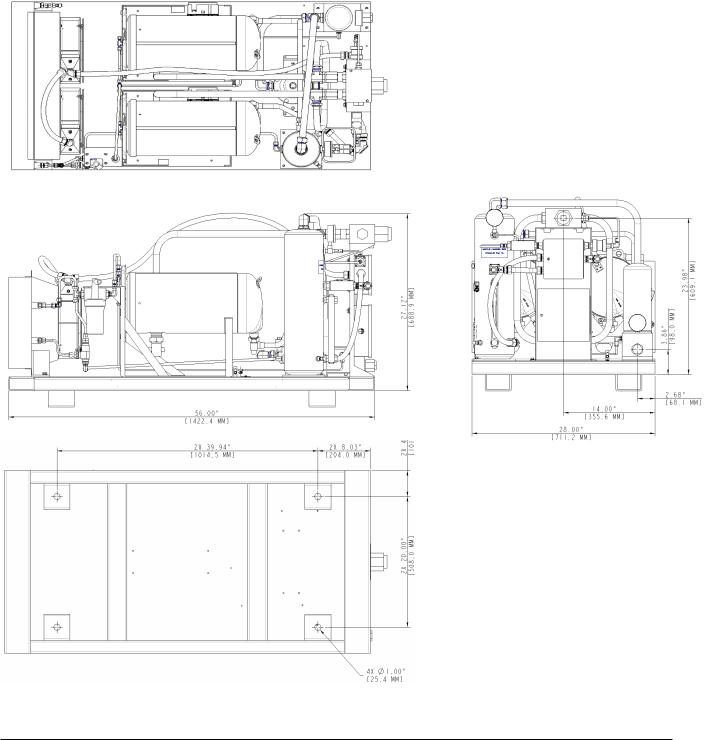
2.4Installation Clearance and Dimensions
Allow sufficient clearance on all sides for service access, especially for gas and electrical connections at the rear of the Compressor Module. Check applicable national and local electrical codes.
Cooling air flow is back to front—from the gas connection end to the oil cooler end. Do not block or restrict the cooler fans or oil cooler.
Refer to Figure 4 for the dimensions of the Compressor Module.
Figure 4 Compressor Module Dimensions, in. (mm)
TOP
VIEW
FRONT
VIEW
SIDE
VIEW
7 |
2006SSD-75 R4 (10/10) |
Dual-Compressor Module |
Installation |
|
|
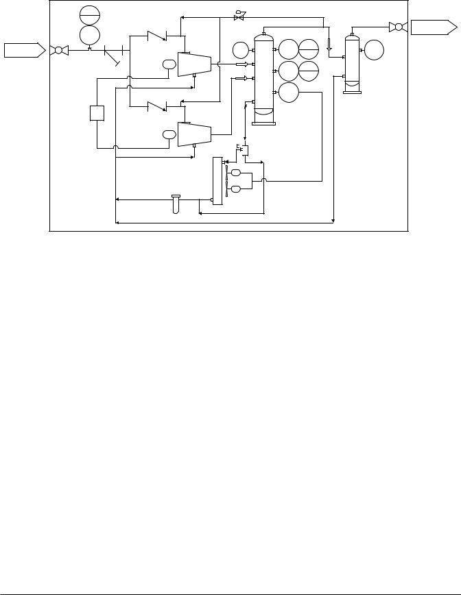
2.5Process and Instrumentation Diagrams (P&IDs)
Figure 5 Compressor Module Gas and Oil Flow Diagram and Safety Shutdowns
|
PSLL |
|
|
|
|
|
001 |
BPV-01 |
|
|
Gas Discharge |
|
|
|
|
||
|
PS |
|
|
|
1" -NPT |
|
001 |
|
|
|
|
Gas Suction |
|
PI |
PS |
PSHH |
PI |
1-1/2" -NPT |
|
002 |
002 |
002 |
003 |
|
|
C-01 |
TS |
TSHH |
|
|
|
|
|
||
|
|
|
002 |
002 |
|
|
|
|
TE |
|
|
|
|
|
002 |
|
SEP-02 |
|
480V |
|
|
|
|
|
J.B. |
|
|
|
|
|
|
C-02 |
SEP-01 |
|
|
|
|
|
|
|
|
|
|
|
TCV-03 |
|
|
|
FL-05 |
EX-04 |
|
|
|
|
|
|
|
|
|
|
Module Limits |
|
|
|
|
Code |
Description |
BPV-01 |
Gas bypass valve (optional) |
C-01 / C-02 |
Compressor and motor |
EX-04 |
Oil cooler, fan controlled by thermistor |
FL-05 |
Oil filter |
PI002 |
Pressure gauge on first-stage oil separator |
PI003 |
Pressure gauge on second-stage oil separator |
PS002 / PSHH002 |
High discharge gas pressure switch |
PS001 / PSLL001 |
Inlet low pressure switch |
SEP-01 |
First-stage oil separator, 6” O.D. |
SEP-02 |
Second-stage oil separator/coalescing element |
TCV-03 |
Thermal bypass valve, 3-way, set @ 200°F (93°C) |
TE002 |
Fan speed thermistor |
TS002 / TSHH002 |
High discharge gas temp switch |
8 |
2006SSD-75 R4 (10/10) |
 Loading...