


 Loading...
Instruction Manual
760008-A
September 2001
Model NGA 2000 TO2
Trace Oxygen Analyzer
http://www.processanalytic.com

ESSENTIAL INSTRUCTIONS
READ THIS PAGE BEFORE PROCEEDING!
Rosemount Analytical designs, manufactures and tests its products to meet many national and international standards. Because these instruments are sophisticated technical products, you MUST properly install, use, and maintain them to ensure they continue to operate within their normal specifications. The following instructions MUST be adhered to and integrated into your safety program when installing, using, and maintaining Rosemount Analytical products. Failure to follow the proper instructions may cause any one of the following situations to occur: Loss of life; personal injury; property damage; damage to this instrument; and warranty invalidation.
•Read all instructions prior to installing, operating, and servicing the product.
•If you do not understand any of the instructions, contact your Rosemount Analytical representative for clarification.
•Follow all warnings, cautions, and instructions marked on and supplied with the product.
•Inform and educate your personnel in the proper installation, operation, and maintenance of the product.
•Install your equipment as specified in the Installation Instructions of the appropriate Instruction Manual and per applicable local and national codes. Connect all products to the proper electrical and pressure sources.
•To ensure proper performance, use qualified personnel to install, operate, update, program, and maintain the product.
•When replacement parts are required, ensure that qualified people use replacement parts specified by Rosemount. Unauthorized parts and procedures can affect the product’s performance, place the safe operation of your process at risk, and VOID YOUR WARRANTY. Look-alike substitutions may result in fire, electrical hazards, or improper operation.
•Ensure that all equipment doors are closed and protective covers are in place, except when maintenance is being performed by qualified persons, to prevent electrical shock and personal injury.
The information contained in this document is subject to change without notice.
Teflon® is a registered trademark of E.I. duPont de Nemours and Co., Inc.
SNOOP® is a registered trademark of NUPRO Co.
Waferpure™ is a trademark of Millipore Corp.
Nanochem® is a registered trademark of Semigas Corp
Emerson Process Management
Rosemount Analytical Inc.
Process Analytic Division
1201 N. Main St. Orrville, OH 44667-0901 T (330) 682-9010
F (330) 684-4434
e-mail: gas.csc@EmersonProcess.com http://www.processanalytic.com

Model NGA 2000 TO2
Instruction Manual
760008-A
September 2001
TABLE OF CONTENTS
PREFACE........................................................................................................................................... |
P-1 |
intended use statement ...................................................................................................................... |
P-1 |
Definitions ........................................................................................................................................... |
P-1 |
Safety Summary ................................................................................................................................. |
P-2 |
General precautions for handling and storing high pressure gas cylinders ....................................... |
P-3 |
Documentation.................................................................................................................................... |
P-4 |
Compliances ....................................................................................................................................... |
P-4 |
Glossary.............................................................................................................................................. |
P-5 |
1-0 |
DESCRIPTION AND SPECIFICATIONS................................................................................. |
1-1 |
|
1-2 |
Overview................................................................................................................................... |
1-1 |
|
1-3 |
Typical Applications.................................................................................................................. |
1-1 |
|
1-4 |
Method of measurement .......................................................................................................... |
1-1 |
|
1-5 |
Features ................................................................................................................................... |
1-1 |
|
|
a. |
General ....................................................................................................................... |
1-4 |
|
b. |
Sample........................................................................................................................ |
1-4 |
|
c. |
Physical....................................................................................................................... |
1-4 |
|
d. |
Gas Connections ........................................................................................................ |
1-5 |
2-0 |
INSTALLATION .................................................................................................................... |
2-1 |
|
2-1 |
Unpacking ................................................................................................................................ |
2-1 |
|
2-2 |
Assembly.................................................................................................................................. |
2-1 |
|
|
a. |
Electrolyte Addition ..................................................................................................... |
2-1 |
2-3 |
Location.................................................................................................................................... |
2-1 |
|
2-4 |
Gases |
....................................................................................................................................... |
2-2 |
|
a. .............................................................................................................. |
Requirements |
2-2 |
|
b. ........................................................................................................................ |
Sample |
2-2 |
|
c. ...................................................................................................................... |
Pressure |
2-2 |
2-5 |
Connections ............................................................................................................................. |
2-2 |
|
|
a. .................................................................................................................... |
Leak Test |
2-3 |
2-6 |
Electrical ..............................................................................................................Connections |
2-3 |
|
3-0 |
OPERATION ............................................................................................................................ |
3-1 |
|
3-1 |
Overview................................................................................................................................... |
3-1 |
|
3-2 Displays & Operating Keys....................................................................................................... |
3-1 |
||
|
a. Menu Lines & Softkey Functionality............................................................................ |
3-2 |
|
|
b. |
Common Function Keys............................................................................................... |
3-2 |
|
c. Entering & Changing Variables.................................................................................... |
3-3 |
|
|
d. |
Starting a Function....................................................................................................... |
3-3 |
|
e. |
Measure Mode Display ................................................................................................ |
3-4 |
|
f. |
Main Menu .................................................................................................................... |
3-4 |
3-3 |
Startup & Initialization............................................................................................................... |
3-6 |
|
|
a. |
Quick Start .................................................................................................................. |
3-7 |
3-4 |
Basic Controls, Setup and Status ............................................................................................ |
3-8 |
|
|
a. |
Analyzer Channel Status ............................................................................................ |
3-8 |
|
b. |
Single Component Display ......................................................................................... |
3-9 |
|
c. |
Multi Component Display ............................................................................................ |
3-10 |
|
d. Basic Controls and Setup ........................................................................................... |
3-11 |
|
Rosemount Analytical Inc. A Division of Emerson Process Management |
Contents i |

Instruction Manual
760008-A
September 2001
Model NGA 2000 TO2
|
e. |
Display Controls .......................................................................................................... |
3-12 |
3-5 Expert Controls and Setup ....................................................................................................... |
3-13 |
||
|
a. |
Calibration Procedure ................................................................................................. |
3-14 |
|
b. |
Alarms ......................................................................................................................... |
3-17 |
|
c. |
Ranges ........................................................................................................................ |
3-18 |
|
d. |
Linearization ................................................................................................................ |
3-19 |
|
e. |
Measurement Display Configuration ........................................................................... |
3-19 |
|
f. |
Concentration Measurement ....................................................................................... |
3-20 |
|
g. |
Flow Measurement ..................................................................................................... |
3-22 |
|
h. |
Temperature Measurement ........................................................................................ |
3-23 |
3-6 System & Network I/O Module Controls (Setup)...................................................................... |
3-24 |
||
|
a. |
System SIO ................................................................................................................. |
3-25 |
|
b. |
Analog Output Setup ................................................................................................... |
3-26 |
|
c. |
Serial Interface Setup .................................................................................................. |
3-29 |
|
d. |
Relay Outputs Setup ................................................................................................... |
3-30 |
|
e. |
System DIO ................................................................................................................. |
3-31 |
3-7 System Configuration and Diagnostics .................................................................................... |
3-32 |
||
|
a. |
Diagnostic Menus ....................................................................................................... |
3-33 |
4-0 |
MAINTENANCE AND SERVICE ............................................................................................. |
4-1 |
|
4-1 |
Overview................................................................................................................................... |
4-1 |
|
4-2 |
Sensor |
...................................................................................................................................... |
4-1 |
|
a. ....................................................................................................................... |
Refilling |
4-2 |
|
b. ............................................................................................. |
Electrolyte Replacement |
4-3 |
|
c. ................................................................................................... |
Sensor Replacement |
4-3 |
4-3 |
Linearization ............................................................................................................................. |
4-4 |
|
4-4 |
Flow Sensor .......................................................................................................Replacement |
4-6 |
|
4-5 |
Electronic ............................................................................................................Components |
4-6 |
|
|
a. .......................................................................................................................... |
Fuses |
4-6 |
|
b. ................................................................................................. |
Printed Circuit Boards |
4-6 |
5.0 |
TROUBLESHOOTING ............................................................................................................. |
5-1 |
|
5-1 |
Troubleshooting........................................................................................................................ |
5-1 |
|
|
a. ...........................................................................Failure to purge down to ppm levels |
5-1 |
|
|
b. ............................................................................................................ |
Flow sensitivity |
5-1 |
|
c. ..........................................................................Erratic and very insensitive readings |
5-1 |
|
6-0 |
REPLACEMENT ........................................................................................................PARTS |
6-1 |
|
6-1 |
Matrix........................................................................................................................................ |
|
6-1 |
6-2 |
Replacement ...................................................................................................................Parts |
6-2 |
|
7-0 |
RETURN ..........................................................................................................OF MATERIAL |
7-1 |
|
7-1 |
Return .....................................................................................................................of Material |
7-1 |
|
7-2 |
Customer .....................................................................................................................Service |
7-1 |
|
7-3 |
Training..................................................................................................................................... |
7-1 |
|
8-0 |
INDEX....................................................................................................................................... |
|
8-1 |
MATERIAL SAFETY DATA SHEET 748377
ii Contents |
Rosemount Analytical Inc. A Division of Emerson Process Management |

Model NGA 2000 TO2
Instruction Manual
760008-A
September 2001
LIST OF ILLUSTRATIONS
Figure 1-1. |
Trace Oxygen Detector Coulometric Principle.............................................................. |
1-2 |
Figure 1-2. |
Trace Oxygen Analyzer Module - Top View ................................................................. |
1-3 |
Figure 2-1. Analyzer Module Interconnection with Instrument Platform ......................................... |
2-4 |
|
Figure 2-2. |
Outline and Mounting Dimensions ................................................................................ |
2-5 |
Figure 2-3. |
Back Panel Connections............................................................................................... |
2-6 |
Figure 2-4. |
Trace Oxygen Analyzer Front Panel............................................................................. |
2-6 |
Figure 3-1. Platform Front Panel ..................................................................................................... |
3-1 |
|
Figure 3-2. |
The Display Screen....................................................................................................... |
3-2 |
Figure 3-3. |
Changing Variables....................................................................................................... |
3-3 |
Figure 3-4. |
Function Confirmation................................................................................................... |
3-3 |
Figure 3-5. |
Measure Mode Display ................................................................................................. |
3-4 |
Figure 3-7. |
Module Manufacturing Data Displays ........................................................................... |
3-5 |
Figure 3-8. |
Startup Display.............................................................................................................. |
3-6 |
Figure 3-9. Initiate Quick Start......................................................................................................... |
3-7 |
|
Figure 3-10. Analyzer Channel Status ............................................................................................. |
3-8 |
|
Figure 3-11. |
Single Component Display............................................................................................ |
3-9 |
Figure 3-12. |
Multi Component Display .............................................................................................. |
3-10 |
Figure 3-13. |
Basic Controls and Setup ............................................................................................. |
3-11 |
Figure 3-14. |
Display Controls ............................................................................................................ |
3-12 |
Figure 3-15. |
Expert Controls and Setup............................................................................................ |
3-13 |
Figure 3-16. |
Calibration – Gas Scale Factor ..................................................................................... |
3-15 |
Figure 3-17. |
Span Calibration............................................................................................................ |
3-16 |
Figure 3-18. |
Alarms ........................................................................................................................... |
3-17 |
Figure 3-19. |
Ranges.......................................................................................................................... |
3-18 |
Figure 3-20. |
Measurement Display Configuration............................................................................. |
3-19 |
Figure 3-21. |
Concentration Measurement......................................................................................... |
3-20 |
Figure 3-22. |
Flow Measurement........................................................................................................ |
3-22 |
Figure 3-23. |
Temperature Measurement .......................................................................................... |
3-23 |
Figure 3-24. |
System & Network I/O Module Controls ....................................................................... |
3-24 |
Figure 3-25. |
System SIO Module ...................................................................................................... |
3-25 |
Figure 3-26. |
System Configuration and Diagnostics......................................................................... |
3-32 |
Figure 4-1. |
Sensor Assembly .......................................................................................................... |
4-2 |
Rosemount Analytical Inc. A Division of Emerson Process Management |
Contents iii |

Instruction Manual
760008-A
September 2001
Model NGA 2000 TO2
iv Contents |
Rosemount Analytical Inc. A Division of Emerson Process Management |
Model NGA 2000 TO2
Instruction Manual
760008-A
September 2001
PREFACE
INTENDED USE STATEMENT
The purpose of this manual is to provide information concerning the components, functions, installation and maintenance of the Model NGA 2000 TO2 and the System Accessories of the NGA 2000 System.
Some sections may describe equipment not used in your configuration. The user should become thoroughly familiar with the operation of this module before operating it. Read this instruction manual completely.
DEFINITIONS
The following definitions apply to DANGERS, WARNINGS, CAUTIONS and NOTES found throughout this publication.
DANGER .
Highlights the presence of a hazard which will cause severe personal injury, death, or substantial property damage if the warning is ignored.
WARNING .
Highlights an operation or maintenance procedure, practice, condition, statement, etc. If not strictly observed, could result in injury, death, or long-term health hazards of personnel.
CAUTION.
Highlights an operation or maintenance procedure, practice, condition, statement, etc. If not strictly observed, could result in damage to or destruction of equipment, or loss of effectiveness.
NOTE
Highlights an essential operating procedure, condition or statement.
Rosemount Analytical Inc. A Division of Emerson Process Management |
Preface P-1 |
Instruction Manual
760008-A
September 2001
Model NGA 2000 TO2
SAFETY SUMMARY
If this equipment is used in a manner not specified in these instructions, protective systems may be impaired.
DANGER.
ELECTRICAL SHOCK HAZARD
Operate this equipment only when covers are secured. Servicing requires access to live parts which can cause death or serious injury. Refer servicing to qualified personnel. For safety and proper performance, this module must be connected to a properly grounded three-wire source of electrical power.
DANGER.
POSSIBLE EXPLOSION HAZARD
This equipment is not designed and should not be used in the analysis of flammable samples. Use of this equipment in this way could result in explosion and death.
WARNING.
HIGH PRESSURE GAS CYLINDERS
This analyzer requires use of pressurized gas. See General Precautions for Handling and Storing High Pressure Cylinders, page P-3.
WARNING.
PARTS INTEGRITY
Tampering or unauthorized substitution of components may adversely affect safety of this product. Use only factory documented components for repair.
CAUTION.
CAUSTIC LIQUID
Electrolyte is a caustic solution. Review the Material Safety Data Sheet in the rear of this manual.
P-2 Preface |
Rosemount Analytical Inc. A Division of Emerson Process Management |

Model NGA 2000 TO2
Instruction Manual
760008-A
September 2001
GENERAL PRECAUTIONS FOR HANDLING AND STORING HIGH
PRESSURE GAS CYLINDERS
Edited from selected paragraphs of the Compressed Gas Association's "Handbook of Compressed Gases" published in 1981
Compressed Gas Association
1235 Jefferson Davis Highway Arlington, Virginia 22202 Used by Permission
1.Never drop cylinders or permit them to strike each other violently.
2.Cylinders may be stored in the open, but in such cases, should be protected against extremes of weather and, to prevent rusting, from the dampness of the ground. Cylinders should be stored in the shade when located in areas where extreme temperatures are prevalent.
3.The valve protection cap should be left on each cylinder until it has been secured against a wall or bench, or placed in a cylinder stand, and is ready to be used.
4.Avoid dragging, rolling, or sliding cylinders, even for a short distance; they should be moved by using a suitable hand-truck.
5.Never tamper with safety devices in valves or cylinders.
6.Do not store full and empty cylinders together. Serious suckback can occur when an empty cylinder is attached to a pressurized system.
7.No part of cylinder should be subjected to a temperature higher than 125°F (52°C). A flame should never be permitted to come in contact with any part of a compressed gas cylinder.
8.Do not place cylinders where they may become part of an electric circuit. When electric arc welding, precautions must be taken to prevent striking an arc against the cylinder.
Rosemount Analytical Inc. A Division of Emerson Process Management |
Preface P-3 |
Instruction Manual
760008-A
September 2001
Model NGA 2000 TO2
DOCUMENTATION
The following NGA 2000 TO2 instruction materials are available. Contact Customer Service Center or the local representative to order.
760008 Instruction Manual (this document)
COMPLIANCES
This product may carry approvals from several certifying agencies for use in non-hazardous, indoor locations. If so, the product will carry approval insignia on the product name-rating plate.
® |
NR T L /C |
Rosemount Analytical Inc. has satisfied all obligations from the European Legislation to harmonize the product requirements in Europe.
These products comply with the standard level of NAMUR EMC. Recommendation (May 1993).
NAMUR
This product satisfies all obligations of all relevant standards of the EMC framework in Australia and New Zealand.
P-4 Preface |
Rosemount Analytical Inc. A Division of Emerson Process Management |
Model NGA 2000 TO2
Instruction Manual
760008-A
September 2001
GLOSSARY OF TERMS
Analyzer Module
The module that contains all sensor/detector components for development of a Primary Variable signal; includes all signal conditioning and temperature control circuitry.
Backplane
The interconnect circuit board which the Controller Board, Power Supply, Analyzer Module power and network cables, I/O Modules and Expansion Modules plug into.
Control Module
The Operator Interface plus the Controller Board.
Controller Board
The computer board that serves as the Network Manager and operates the Display and Keypad.
Distribution Assembly
The Backplane and the card cages that hold I/O and Expansion Modules.
Expansion Module
A circuit board that plugs into the Backplane from the front of the Platform and performs special features not related to I/O functions.
I/O Module
A circuit board that plugs into the Backplane from the rear of the Platform. Has a connector terminal for communication with external data acquisition devices and provides an input/output function.
Operator Interface
The Display and Keyboard.
Platform
Any workable collection of the following: Controller Board, Power Supply, Distribution Assembly, Enclosure and Operator Interface.
Power Supply
Any of a variety of components that provides conditioned power to other NGA 2000 components, from the Power Supply Board that plugs into the front of the Backplane in a stand-alone instrument to several larger ones that can power larger collections of modules and components.
Primary Variable
The measured species concentration value from an Analyzer Module.
Secondary Variable
Data placed on the network by a module regarding current status, e.g., sample flow, source voltage and other diagnostic information.
Rosemount Analytical Inc. A Division of Emerson Process Management |
Preface P-5 |

Instruction Manual
760008-A
September 2001
Softkeys
Model NGA 2000 TO2
The five function keys located below the front panel display; they assume the function displayed directly above each on the display, a function dictated by software.
System
Any collection of Analyzer Module(s), Platform(s), I/O Module(s) and Expansion Module(s).
P-6 Preface |
Rosemount Analytical Inc. A Division of Emerson Process Management |

Model NGA 2000 TO2
Instruction Manual
760008-A
September 2001
SECTION 1
DESCRIPTION AND SPECIFICATIONS
1-1 OVERVIEW
This manual describes the Trace Oxygen (TO2) Analyzer Module of Rosemount Analytical's NGA 2000 Series of gas analysis components.
The TO2 Analyzer Module is designed to continuously determine the concentration of trace oxygen in a flowing gaseous mixture. The concentration is expressed in parts-per- million.
The TO2 Analyzer Module is configured as a shelf-mount module, designed to be installed external from the platform on an associated shelf capable of holding two modules side-by- side, with gas connections made from the rear. All electronics relative to sample detection and conditioning are included in this module.
1-2 TYPICAL APPLICATIONS
The TO2 Analyzer Module has specific applications in the following areas:
•Trace oxygen in product nitrogen and argon streams from air separation plants
•Trace oxygen in inerting atmospheres for heat treat furnaces
•Trace oxygen in glove-box applications
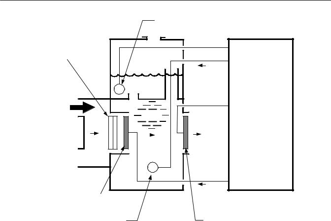
1-3 METHOD OF MEASUREMENT
Coulometric Principle
The TO2 Analyzer Module uses the coulometric principle of oxygen detection. This technology is based on the fact that oxygen in the sample is reduced by an electrochemical reaction. This reduction occurs at the cathode and results in the generation of hydroxyl ions. These hydroxyl ions migrate to the anode where they are oxidized to reform oxygen. The oxidation reaction generates four electrons which in turn migrate to the anode to participate in the reduction reaction:
(Cathode Reaction)
O2 + 2 H2O + 4 e- → 4 OH- (Anode Reaction)
4 OH- → O2 + 2 H2O + 4 e-
A polarizing voltage of approximately 1.3 VDC is applied between the anode and cathode to drive the oxidation and reduction reactions.
The resulting current flow produced by the flow of electrons is directly proportional to the oxygen content in the sample gas.
1-4 FEATURES
Among the features included in the TO2 Analyzer Module are:
•Quick start feature
•Electrolyte level alarm
•High oxygen protection circuit with alarm
•Sample flow indication.
Rosemount Analytical Inc. A Division of Emerson Process Management |
Description and Specifications 1-1 |
Instruction Manual
760008-A
September 2001
Model NGA 2000 TO2
SECONDARY ANODE (+)
BI-STRATA™ DIFFUSION BAR-
RIER
e-
ELECTRONICS
S
SAMPLE IN
KOH
O2 |
|
|
|
OH- |
O2 |
||
SAMPLE OUT 
S
e-
O2 SENSING CATHODE (-)
SECONDARY CATHODE (-) |
O2 SENSING ANODE (-) |
Figure 1-1. Trace Oxygen Detector Coulometric Principle
1-2 |
Description and Specifications |
Rosemount Analytical Inc. A Division of Emerson Process Management |

Model NGA 2000 TO2
Instruction Manual
760008-A
September 2001
|
Sensor Assembly |
Network/Power |
|
Module |
Sensor |
|
|
Computer |
Sample Flow |
Board |
Sensor |
Power Board |
|
Figure 1-2. Trace Oxygen Analyzer Module - Top View
Rosemount Analytical Inc. A Division of Emerson Process Management |
Description and Specifications 1-3 |

Instruction Manual
760008-A
September 2001
Model NGA 2000 TO2
1-5 SPECIFICATIONS1 |
|
a. General |
|
Measurement Species................................... |
Trace Oxygen |
Ranges .......................................................... |
0 to 100 ppm (output scalable down to 0-2 ppm fullscale) |
Accuracy........................................................ |
±3% of reading or ±0.02% of range (except for ranges ≤ |
|
100 ppm: ±3% of reading or ±0.05% of range) |
Sensitivity ...................................................... |
<10 ppb Oxygen |
Noise ............................................................. |
1% of fullscale, peak to peak |
Linearity ......................................................... |
±1% of fullscale |
Response Time ............................................. |
Typically 90% in less than 20 seconds |
Zero Drift........................................................ |
≤±1% of fullscale/24 hours at constant temperature |
Span Drift....................................................... |
≤±1% of fullscale/24 hours at constant temperature |
Effect of Temperature.................................... |
0.32% of reading per °F from 70°F (0.58% of reading per |
|
°C from 21°C) |
Effect of Flow................................................. |
≤2% of reading for a flow change of ±250 cc/min (0.5 |
|
SCFH) |
Operating Temperature ................................. |
32°F to 113°F (0°C to 45°C) |
Power Requirements..................................... |
+24 VDC ±5%, 10 W max. |
Ripple and Noise ........................................... |
<100 mV peak to peak |
Line and Load Regulations............................ |
<±1% |
b. Sample |
|
Sample .......................................................... |
Non-flammable (below 100% of the LEL) |
Flow Rate ...................................................... |
0.5 to 1.5 L/min. |
Supply Pressure ............................................ |
1027 to 1082 hPa - absolute (0.2 to 1.0 psig) |
Temperature.................................................. |
32°F to 113°F (0°C to 45°C) |
Particulates.................................................... |
filtered to <0.1 mg/L; non-condensing at ambient tem- |
|
perature |
Sample Humidity ........................................... |
non-condensing at ambient temperatures |
c. Physical |
|
Materials in contact with sample ................... |
Stainless steel, Teflon, Delrin, neoprene |
Dimensions.................................................... |
See Figure 2-2, Outline and Mounting Dimensions |
Weight ........................................................... |
6.8 kg (15 lbs.) |
Mounting........................................................ |
Horizontal, external to Platform or custom installed in a |
|
panel |
Case Classification........................................ |
General Purpose for installation in weather protected |
|
area |
Max. Separation from Platform...................... |
1600 m (1 mile) |
1 See the Platform manual for specifications regarding Platform related components.
1-4 |
Description and Specifications |
Rosemount Analytical Inc. A Division of Emerson Process Management |

Model NGA 2000 TO2
Instruction Manual
760008-A
September 2001
d. Gas Connections |
|
Sample In ...................................................... |
1/4 inch O.D. tube fitting |
Sample Out.................................................... |
1/4 inch O.D. tube fitting |
Rosemount Analytical Inc. A Division of Emerson Process Management |
Description and Specifications 1-5 |

Instruction Manual
760008-A
September 2001
Model NGA 2000 TO2
1-6 |
Description and Specifications |
Rosemount Analytical Inc. A Division of Emerson Process Management |

Model NGA 2000 TO2
Instruction Manual
760008-A
September 2001
SECTION 2
INSTALLATION
WARNING.
Before starting to install this equipment, read the Safety Summary in the Preface section of this manual. Failure to follow the safety instructions could result in serious injury or death.
2-1 UNPACKING
If the Trace Oxygen (TO2) Analyzer Module is received as a separate unit, carefully examine the shipping carton and contents for signs of damage. Immediately notify the shipping carrier if the carton or contents is damaged. Retain the carton and packing material until all components associated with the TO2 Analyzer Module are operational.
2-2 ELECTROLYTE
Figure 4-1). Be careful not to lose these screws as they have metric threads. Carefully lift out the Sensor assembly and remove from the analyzer module. Place on a flat surface and remove the black Sensor cover by unscrewing counterclockwise.
Add distilled or deionized water to the Sensor to the maximum level indication on the Sensor reservoir. Let Sensor stand for approximately 15 minutes and check for leaks around the base of the reservoir, and at the seams and corners. If a leak is found, contact the factory before proceeding. Drain the Sensor.
Fill the Sensor with one bottle of electrolyte supplied with the analyzer module. Use the entire contents of the bottle.
NOTE
Before installation of the TO2 Analyzer Module, electrolyte must be added to the Sensor. Follow the procedure described in Section 2- 2a.
After addition of electrolyte, locate the analyzer module on an appropriate mounting surface and connect the network cable to either the NETWORK 1 or NETWORK 2 connection on the Analyzer Module, and the NETWORK connection on the Platform network I/O port. (See Figure 2-1 and Figure 2-4.)
a.Electrolyte Addition
Before adding electrolyte to the Sensor, it is recommended to check the Sensor for possible leakage caused by damage in shipment. To check the Sensor for leakage, remove the top cover of the Analyzer Module and locate and remove the 5 mounting screws which hold the Sensor Assembly (Sensor, flow meter, plumbing, inlet/outlet fittings) to the module (see
Do not add water. The volume and concentration of the bottled electrolyte is pre-measured.
Reinstall the black Sensor cover and carefully reinstall the Sensor Assembly inside the Analyzer Module. Do not tilt the Sensor Assembly excessively as electrolyte may leak out.
2-3 LOCATION
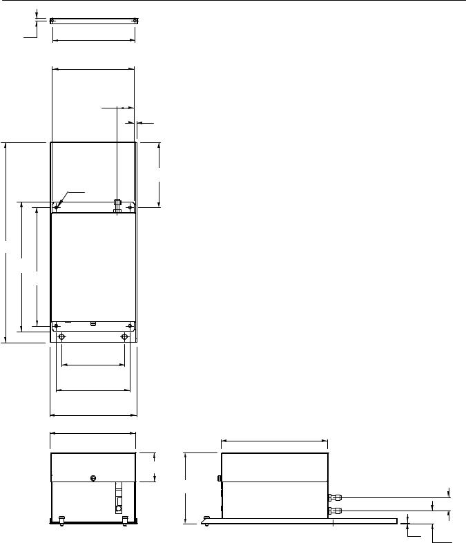
(See Figure 2-2) The TO2 Analyzer Module comes standard with mounting ears for easy installation on flat, horizontal surfaces. Install the TO2 Analyzer Module in a clean, weatherproofed, vibration-free location free from extreme temperature variations and moisture. For best results, install the instrument near the sample stream to minimize sample transport time.
Operating ambient temperature is 0 °C to 45 °C (32 °F to 81 °F). Temperature change should not exceed 10 °C (18 °F) per hour.
Rosemount Analytical Inc. A Division of Emerson Process Management |
Installation 2-1 |

Instruction Manual
760008-A
September 2001
Model NGA 2000 TO2
The same temperature restrictions apply to the location of the zero and span gas cylinders.
2-4 GASES
a.Requirements
The TO2 Analyzer Module requires only a standard of accurately known composition for use as a span gas. The span gas should be supplied from a cylinder equipped with a clean, metallic diaphragm, two-stage regulator. A shutoff valve is recommended.
Calibration Gases
The TO2 module does not require routine zero calibration. The zero is factory set and does not experience routine drift. Over long periods of time, the zero may experience minor drift. For low ppm range analyzers, you may wish to check the zero at one year intervals. Oxygenfree nitrogen is recommended for use as zero gas. This gas is certified to <0.5 ppm oxygen and can be improved by passing the zero gas through an oxygen scrubber such as Millipore™ Waferpure or Semigas Nanochem® resin purifiers. A mixture of trace oxygen in a background of nitrogen is recommended as span gas. For maximum accuracy, the concentration of trace oxygen in the span gas should be as high as possible for the range of measurement.
Module to control flow, the inlet pressure to the needle valve should not exceed 345 hPa (5 psig). A constant sample flow rate between 1.0 to 3.0 SCFH (0.5 to 1.5 l/min) is recommended for best results. The Analyzer Module must vent to atmosphere to avoid back pressure influences on the oxygen reading.
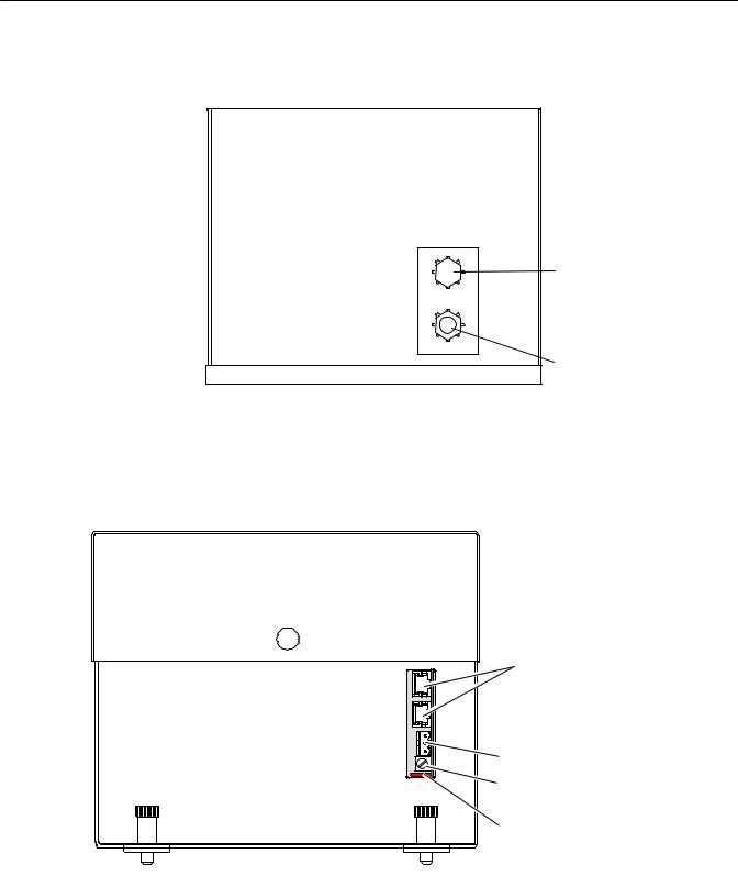
2-5 GAS CONNECTIONS
(See Figure 2-3. ) Connect inlet and outlet lines for sample to appropriately labeled fittings on the rear panel. SAMPLE IN and SAMPLE OUT are 1/4-inch ferrule-type compression fittings. Zero and span gases should be introduced at the SAMPLE IN fitting at normal sample inlet flow rate.
Metallic tubing is recommended for the sample line. The use of plastic, Teflon, or other non-metallic tubing can result in ambient oxygen permeation through the tubing causing higher than expected reading. Exhaust tubing should be 1/4 inch (6.3 mm) or larger, and can be metallic or non-metallic.
CAUTION.
GAS OVERPRESSURE
At no time should sample, zero or span gas inlet pressure exceed 69 hPa - gauge (1.0 psig). Damage to the Sensor may occur if this pressure level is exceeded.
b.Sample
The sample must be clean and dry before entering the Analyzer Module. Sample should be filtered for particulates down to two microns, and should have a dew point at least 5 °C (13 °F) below the coldest expected ambient temperature.
c.Pressure
CAUTION.
SAMPLE FLOW
Do not test the sample pressure by blocking the exhaust. When the pressure is released the sudden surge of flow will spin the internal flowmeter off its bearings and destroy it.
Constant between 13.8 and 69 hPa - gauge (0.2 and 1.0 psig) sample inlet pressure is recommended. If a needle valve is used upstream of the Analyzer
2-2 Installation |
Rosemount Analytical Inc. A Division of Emerson Process Management |
Model NGA 2000 TO2
Instruction Manual
760008-A
September 2001
a.Leak Test
The TO2 Analyzer Module is completely tested at the factory for gas leakage. The user is responsible for testing for leakage only at the inlet and outlet fittings on the rear panel.
CAUTION.
SENSOR DAMAGE
Do not expose the Sensor to pressure in excess of 1.0 psig as this may cause damage.
Flow Indicator Method
Supply air or inert gas such as nitrogen, at 1 psig (6.8 hPa), to the analyzer through a flow indicator with a range of 0 to 250 cc/min. Install a shut-off valve at the sample gas outlet. Set the flow rate to 125 cc/min.
Close the outlet shut-off valve and notice that the flow reading drops to zero. If the flow reading does not drop to zero, the system is leaking and must be corrected before the introduction of sample gas or the application of power.
2-6 ELECTRICAL CONNECTIONS
WARNING.
ELECTRICAL SHOCK HAZARD
Operate this equipment only when covers are secured. Servicing requires access to live parts which can cause death or serious injury. Refer servicing to qualified personnel. For safety and proper performance, this module must be connected to a properly grounded three-wire source of electrical power.
Electrical connections must be made in compliance with National Electrical Code (ANSI/NFPA 70) and/or any applicable national or electrical codes.
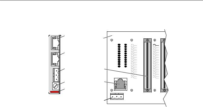
Two electrical connections are required on the Analyzer Module: POWER and NETWORK (See Figure 2-4). On the Analyzer Module, two NETWORK connectors are available, either of which is appropriate for: 1) interconnection with the Backplane of the Platform or 2) "daisy-chaining" with other NGA 2000 components (A star connection is acceptable for LON lengths under about 10 meters.)
Connect a source of 24 V 5A DC power to the power inlet. Make sure that the ground connection is made, and that this is separate from the power return lead. Failure to ensure a good ground may result in random noise and disturbance in the analyzer readings.
Rosemount Analytical Inc. A Division of Emerson Process Management |
Installation 2-3 |
Instruction Manual
760008-A
September 2001
Model NGA 2000 TO2
ANALYZER MODULE |
|
CONNECTIONS |
|
Network 1 |
Backplane |
|
|
Network 2 |
|
Power |
Controller Board |
|
Connector |
Fuse |
Network |
Power Indicator Light |
|
|
Power |
BACKPLANE |
CONNECTIONS |
Figure 2-1. Analyzer Module Interconnection with Instrument Platform
2-4 Installation |
Rosemount Analytical Inc. A Division of Emerson Process Management |
Model NGA 2000 TO2
Instruction Manual
760008-A
September 2001
.23
[6]
18.56
[471]
12.00
[305]
11.00
[279]
7.75
[197]
7.75
[197]
1.61
[41]
.23
[6]
5.78
[147]
[6.75].266 DIA
6.00
[152]
7.00
[178]
8.25
[206]
8.10 [206] 10.15
[258]
2.70
[68]
6.62
[168]
.06
[1.5]
Figure 2-2. Outline and Mounting Dimensions
1.2
[31]
1.2
[31]
Rosemount Analytical Inc. A Division of Emerson Process Management |
Installation 2-5 |
Instruction Manual
760008-A
September 2001
Model NGA 2000 TO2
 Sample
Inlet
1/4" Tube
 Sample
Exhaust
1/4" Tube
Figure 2-3. Back Panel Connections
Network Connections |
Power Connection |
Fuse |
Power Indicator Light |
Figure 2-4. Trace Oxygen Analyzer Front Panel
2-6 Installation |
Rosemount Analytical Inc. A Division of Emerson Process Management |
Loading...