


 Loading...
Configuration and Use Manual
MMI-20021712, Rev AB
April 2013
Micro Motion® Model 1700 Transmitters with Analog Outputs
Includes the Chinese-Language Display Option
Safety messages
Safety messages are provided throughout this manual to protect personnel and equipment. Read each safety message carefully before proceeding to the next step.
Micro Motion customer service
•Worldwide: flow.support@emerson.com
•Asia-Pacific: APflow.support@emerson.com
North and South America |
Europe and Middle East |
Asia Pacific |
|
|
|||
|
|
|
|
|
|
|
|
United States |
800-522-6277 |
U.K. |
0870 240 1978 |
Australia |
800 |
158 727 |
|
|
|
|
|
|
|
|
|
Canada |
+1 303-527-5200 |
The Netherlands |
+31 (0) 318 495 555 |
New Zealand |
099 |
128 804 |
|
|
|
|
|
|
|
|
|
Mexico |
+41 |
(0) 41 7686 111 |
France |
0800 917 901 |
India |
800 |
440 1468 |
|
|
|
|
|
|
|
|
Argentina |
+54 |
11 4837 7000 |
Germany |
0800 182 5347 |
Pakistan |
888 |
550 2682 |
|
|
|
|
|
|
|
|
Brazil |
+55 |
15 3238 3677 |
Italy |
8008 77334 |
China |
+86 |
21 2892 9000 |
|
|
|
|
|
|
|
|
Venezuela |
+58 |
26 1731 3446 |
Central & Eastern |
+41 (0) 41 7686 111 |
Japan |
+81 |
3 5769 6803 |
|
|
|
|
|
|
|
|
|
|
|
Russia/CIS |
+7 495 981 9811 |
South Korea |
+82 |
2 3438 4600 |
|
|
|
|
|
|
|
|
|
|
|
Egypt |
0800 000 0015 |
Singapore |
+65 |
6 777 8211 |
|
|
|
|
|
|
|
|
|
|
|
Oman |
800 70101 |
Thailand |
001 |
800 441 6426 |
|
|
|
|
|
|
|
|
|
|
|
Qatar |
431 0044 |
Malaysia |
800 |
814 008 |
|
|
|
|
|
|
|
|
|
|
|
Kuwait |
663 299 01 |
|
|
|
|
|
|
|
|
|
|
|
|
|
|
South Africa |
800 991 390 |
|
|
|
|
|
|
|
|
|
|
|
|
|
|
Saudia Arabia |
800 844 9564 |
|
|
|
|
|
|
|
|
|
|
|
|
|
|
UAE |
800 0444 0684 |
|
|
|
|
|
|
|
|
|
|
|

Contents
Contents
Part I |
Getting Started |
|
|
Chapter 1 |
Before you begin ............................................................................................................ |
2 |
|
|
1.1 |
About this manual ....................................................................................................................... |
2 |
|
1.2 |
Transmitter model code .............................................................................................................. |
2 |
|
1.3 |
Communications tools and protocols .......................................................................................... |
2 |
|
1.4 |
Additional documentation and resources .................................................................................... |
3 |
Chapter 2 |
Quick start ..................................................................................................................... |
5 |
|
|
2.1 |
Power up the transmitter ............................................................................................................. |
5 |
|
2.2 |
Check flowmeter status ............................................................................................................... |
5 |
|
2.3 |
Make a startup connection to the transmitter .............................................................................. |
7 |
|
2.4 |
Characterize the flowmeter (if required) ...................................................................................... |
8 |
|
2.5 |
Verify mass flow measurement ................................................................................................. |
11 |
|
2.6 |
Verify the zero ........................................................................................................................... |
12 |
Part II |
Configuration and commissioning |
|
|
Chapter 3 |
Introduction to configuration and commissioning ....................................................... |
17 |
|
|
3.1 |
Configuration flowchart ............................................................................................................ |
17 |
|
3.2 |
Default values and ranges .......................................................................................................... |
19 |
|
3.3 |
Enable access to the off-line menu of the display ....................................................................... |
19 |
|
3.4 |
Disable write-protection on the transmitter configuration ........................................................ |
19 |
|
3.5 |
Restore the factory configuration .............................................................................................. |
20 |
Chapter 4 |
Configure process measurement .................................................................................. |
21 |
|
|
4.1 |
Configure mass flow measurement ........................................................................................... |
21 |
|
4.2 |
Configure volume flow measurement for liquid applications ..................................................... |
27 |
|
4.3 |
Configure gas standard volume (GSV) flow measurement ......................................................... |
32 |
|
4.4 |
Configure Flow Direction .............................................................................................................. |
38 |
|
4.5 |
Configure density measurement ............................................................................................... |
44 |
|
4.6 |
Configure temperature measurement ....................................................................................... |
49 |
|
4.7 |
Configure pressure compensation ............................................................................................. |
52 |
Chapter 5 |
Configure device options and preferences .................................................................... |
58 |
|
|
5.1 |
Configure the transmitter display .............................................................................................. |
58 |
|
5.2 |
Enable or disable operator actions from the display ................................................................... |
64 |
|
5.3 |
Configure security for the display menus .................................................................................. |
66 |
|
5.4 |
Configure response time parameters ........................................................................................ |
68 |
|
5.5 |
Configure alarm handling .......................................................................................................... |
71 |
|
5.6 |
Configure informational parameters ......................................................................................... |
76 |
Chapter 6 |
Integrate the meter with the control system ................................................................ |
80 |
|
|
6.1 |
Configure the transmitter channels ........................................................................................... |
80 |
|
6.2 |
Configure the mA output .......................................................................................................... |
81 |
|
6.3 |
Configure the frequency output ................................................................................................ |
88 |
Configuration and Use Manual |
i |

Contents
|
6.4 |
Configure the discrete output ................................................................................................... |
93 |
|
6.5 |
Configure events ....................................................................................................................... |
99 |
|
6.6 |
Configure digital communications .......................................................................................... |
102 |
Chapter 7 |
Completing the configuration .................................................................................... |
112 |
|
|
7.1 |
Test or tune the system using sensor simulation ...................................................................... |
112 |
|
7.2 |
Back up transmitter configuration ........................................................................................... |
114 |
|
7.3 |
Enable write-protection on the transmitter configuration ....................................................... |
115 |
Part III |
Operations, maintenance, and troubleshooting |
|
|
Chapter 8 |
Transmitter operation ................................................................................................ |
117 |
|
|
8.1 |
Record the process variables ................................................................................................... |
117 |
|
8.2 |
View process variables ............................................................................................................. |
118 |
|
8.3 |
View transmitter status using the status LED ........................................................................... |
120 |
|
8.4 |
View and acknowledge status alarms ...................................................................................... |
121 |
|
8.5 |
Read totalizer and inventory values ......................................................................................... |
128 |
|
8.6 |
Start and stop totalizers and inventories .................................................................................. |
129 |
|
8.7 |
Reset totalizers ........................................................................................................................ |
130 |
|
8.8 |
Reset inventories ..................................................................................................................... |
132 |
Chapter 9 |
Measurement support ............................................................................................... |
133 |
|
|
9.1 |
Options for measurement support .......................................................................................... |
133 |
|
9.2 |
Use Smart Meter Verification ................................................................................................... |
133 |
|
9.3 |
Zero the flowmeter ................................................................................................................. |
152 |
|
9.4 |
Validate the meter ................................................................................................................... |
159 |
|
9.5 |
Perform a (standard) D1 and D2 density calibration ................................................................. |
161 |
|
9.6 |
Perform a D3 and D4 density calibration (T-Series sensors only) .............................................. |
166 |
|
9.7 |
Perform temperature calibration ............................................................................................. |
170 |
Chapter 10 |
Troubleshooting ........................................................................................................ |
173 |
|
|
10.1 |
Status LED states ..................................................................................................................... |
174 |
|
10.2 |
Status alarms ........................................................................................................................... |
174 |
|
10.3 |
Flow measurement problems .................................................................................................. |
186 |
|
10.4 |
Density measurement problems ............................................................................................. |
188 |
|
10.5 |
Temperature measurement problems ..................................................................................... |
189 |
|
10.6 |
Milliamp output problems ....................................................................................................... |
190 |
|
10.7 |
Frequency output problems .................................................................................................... |
191 |
|
10.8 |
Use sensor simulation for troubleshooting .............................................................................. |
192 |
|
10.9 |
Check power supply wiring ...................................................................................................... |
192 |
|
10.10 |
Check sensor-to-transmitter wiring ......................................................................................... |
193 |
|
10.11 |
Check grounding ..................................................................................................................... |
193 |
|
10.12 |
Perform loop tests ................................................................................................................... |
194 |
|
10.13 |
Trim mA outputs ..................................................................................................................... |
201 |
|
10.14 |
Check the HART communication loop ..................................................................................... |
203 |
|
10.15 |
Check HART Address and Loop Current Mode ................................................................................ |
204 |
|
10.16 |
Check HART burst mode .......................................................................................................... |
204 |
|
10.17 |
Check Lower Range Value and Upper Range Value ......................................................................... |
204 |
|
10.18 |
Check mA Output Fault Action ...................................................................................................... |
204 |
|
10.19 |
Check for radio frequency interference (RFI) ............................................................................ |
205 |
|
10.20 |
Check Frequency Output Maximum Pulse Width ............................................................................... |
205 |
|
10.21 |
Check Frequency Output Scaling Method ........................................................................................ |
205 |
ii |
Micro Motion® Model 1700 Transmitters with Analog Outputs |
|
|
|
Contents |
|
|
|
|
|
10.22 |
Check Frequency Output Fault Action ............................................................................................. |
206 |
|
10.23 |
Check Flow Direction .................................................................................................................. |
206 |
|
10.24 |
Check the cutoffs .................................................................................................................... |
206 |
|
10.25 |
Check for slug flow (two-phase flow) ....................................................................................... |
207 |
|
10.26 |
Check the drive gain ................................................................................................................ |
207 |
|
10.27 |
Check the pickoff voltage ........................................................................................................ |
208 |
|
10.28 |
Check for electrical shorts ....................................................................................................... |
209 |
|
10.29 |
Check the core processor LED .................................................................................................. |
212 |
|
10.30 |
Perform a core processor resistance test ................................................................................. |
215 |
Appendices and reference |
|
||
Appendix A |
Using the standard transmitter display ...................................................................... |
218 |
|
|
A.1 |
Components of the transmitter interface ................................................................................ |
218 |
|
A.2 |
Use the optical switches .......................................................................................................... |
219 |
|
A.3 |
Access and use the display menu system ................................................................................. |
220 |
|
A.4 |
Display codes for process variables .......................................................................................... |
224 |
|
A.5 |
Codes and abbreviations used in display menus ...................................................................... |
225 |
|
A.6 |
Menu maps for the transmitter display .................................................................................... |
229 |
Appendix B |
Using the Chinese-language display ........................................................................... |
240 |
|
|
B.1 |
Components of the transmitter interface ................................................................................ |
240 |
|
B.2 |
Use the optical switches .......................................................................................................... |
241 |
|
B.3 |
Access and use the display menu system ................................................................................. |
242 |
|
B.4 |
Menu maps for the transmitter display .................................................................................... |
247 |
Appendix C |
Using ProLink II with the transmitter .......................................................................... |
259 |
|
|
C.1 |
Basic information about ProLink II ........................................................................................... |
259 |
|
C.2 |
Connect with ProLink II ............................................................................................................ |
260 |
|
C.3 |
Menu maps for ProLink II ......................................................................................................... |
273 |
Appendix D |
Using ProLink III with the transmitter ......................................................................... |
281 |
|
|
D.1 |
Basic information about ProLink III ........................................................................................... |
281 |
|
D.2 |
Connect with ProLink III ........................................................................................................... |
282 |
|
D.3 |
Menu maps for ProLink III ........................................................................................................ |
295 |
Appendix E |
Using the Field Communicator with the transmitter ................................................... |
302 |
|
|
E.1 |
Basic information about the Field Communicator .................................................................... |
302 |
|
E.2 |
Connect with the Field Communicator .................................................................................... |
303 |
|
E.3 |
Menu maps for the Field Communicator .................................................................................. |
306 |
Appendix F |
Default values and ranges .......................................................................................... |
320 |
|
|
F.1 |
Default values and ranges ........................................................................................................ |
320 |
Appendix G |
Transmitter components and installation wiring ........................................................ |
325 |
|
|
G.1 |
Installation types ..................................................................................................................... |
325 |
|
G.2 |
Power supply terminals and ground ........................................................................................ |
329 |
|
G.3 |
Input/output (I/O) wiring terminals ......................................................................................... |
330 |
Appendix H |
NE 53 history .............................................................................................................. |
331 |
|
|
H.1 |
NE 53 history ........................................................................................................................... |
331 |
Index ................................................................................................................................................ |
|
|
336 |
Configuration and Use Manual |
iii |

Contents
iv |
Micro Motion® Model 1700 Transmitters with Analog Outputs |

Getting Started
Part I
Getting Started
Chapters covered in this part:
•Before you begin
•Quick start
Configuration and Use Manual |
1 |

Before you begin
1 Before you begin
Topics covered in this chapter:
•About this manual
•Transmitter model code
•Communications tools and protocols
•Additional documentation and resources
1.1About this manual
This manual provides information to help you configure, commission, use, maintain, and troubleshoot the Micro Motion transmitter.
Important
This manual assumes that the transmitter has been installed correctly and completely, according to the instructions in the transmitter installation manual, and that the installation complies with all applicable safety requirements.
1.2Transmitter model code
Your transmitter can be identified by the model number on the transmitter tag.
The transmitter has a model number of the following form:
1700(I/R/C/B)**A******
IIntegral mount
R 4-wire remote-mount
C9-wire remote-mount
BRemote core processor with remote transmitter
AAnalog outputs option board
1.3Communications tools and protocols
You can use several different communications tools and protocols to interface with the transmitter. You may use different tools in different locations or for different tasks.
2 |
Micro Motion® Model 1700 Transmitters with Analog Outputs |

|
|
|
|
|
|
Before you begin |
|
|
|
||||
Table 1-1: Communications tools, protocols, and related information |
|
|
||||
|
|
|
|
|
|
|
Communica- |
|
|
|
|
|
|
tions tool |
Supported protocols |
Scope |
In this manual |
For more information |
||
|
|
|
|
|
||
Display (stand- |
Not applicable |
Basic configuration and |
Complete user informa- |
Not applicable |
||
ard) |
|
|
commissioning |
tion. See Appendix A. |
|
|
|
|
|
|
|
||
Chinese-lan- |
Not applicable |
Basic configuration and |
Complete user informa- |
Not applicable |
||
guage display |
|
|
commissioning |
tion. See Appendix B. |
|
|
|
|
|
|
|
|
|
ProLink II |
• |
HART/RS-485 (1) |
Complete configuration |
Basic user information. |
User manual |
|
|
• |
HART/Bell 202 |
and commissioning |
See Appendix C. |
• |
Installed with soft- |
|
• |
Modbus/RS-485 |
|
|
|
ware |
|
• |
Service port |
|
|
• |
On Micro Motion |
|
|
|
|
|
|
user documentation |
|
|
|
|
|
|
CD |
|
|
|
|
|
• |
On Micro Motion |
|
|
|
|
|
|
web site (www.mi- |
|
|
|
|
|
|
cromotion.com |
|
|
|
|
|
|
|
ProLink III |
• |
HART/RS-485 (1) |
Complete configuration |
Basic user information. |
User manual |
|
|
• |
HART/Bell 202 |
and commissioning |
See Appendix D. |
• |
Installed with soft- |
|
• |
Modbus/RS-485 |
|
|
|
ware |
|
• |
Service port |
|
|
• |
On Micro Motion |
|
|
|
|
|
|
user documentation |
|
|
|
|
|
|
CD |
|
|
|
|
|
• |
On Micro Motion |
|
|
|
|
|
|
web site (www.mi- |
|
|
|
|
|
|
cromotion.com |
|
|
|
|
|
||
Field Commu- |
HART/Bell 202 |
Complete configuration |
Basic user information. |
User manual on |
||
nicator |
|
|
and commissioning |
See Appendix E. |
Micro Motion web site |
|
|
|
|
|
|
(www.micromo- |
|
|
|
|
|
|
tion.com |
|
|
|
|
|
|
|
|
Tip
You may be able to use other communications tools from Emerson Process Management, such as AMS Suite: Intelligent Device Manager, or the Smart Wireless THUM™ Adapter. Use of AMS or the Smart Wireless THUM Adapter is not discussed in this manual. The AMS interface is similar to the ProLink II interface. For more information on the Smart Wireless THUM Adapter, refer to the documentation available at www.micromotion.com.
1.4Additional documentation and resources
Micro Motion provides additional documentation to support the installation and operation of the transmitter.
(1) Devices with the Chinese-language display do not support HART/RS-485.
Configuration and Use Manual |
3 |

Before you begin
Table 1-2: Additional documentation and resources
Topic |
Document |
|
|
Sensor |
Sensor documentation |
|
|
Transmitter installation |
|
|
|
Hazardous area installation |
See the approval documentation shipped with the transmitter, or |
|
download the appropriate documentation from the Micro Motion |
|
web site at www.micromotion.com. |
|
|
All documentation resources are available on the Micro Motion web site at
www.micromotion.com or on the Micro Motion user documentation CD.
4 |
Micro Motion® Model 1700 Transmitters with Analog Outputs |
Quick start
2 Quick start
Topics covered in this chapter:
•Power up the transmitter
•Check flowmeter status
•Make a startup connection to the transmitter
•Characterize the flowmeter (if required)
•Verify mass flow measurement
•Verify the zero
2.1Power up the transmitter
The transmitter must be powered up for all configuration and commissioning tasks, or for process measurement.
1.Ensure that all transmitter and sensor covers and seals are closed.
 CAUTION!
To prevent ignition of flammable or combustible atmospheres, ensure that all covers and seals are tightly closed. For hazardous area installations, applying power while housing covers are removed or loose can cause an explosion.
2.Turn on the electrical power at the power supply.
The transmitter will automatically perform diagnostic routines. During this period, Alarm 009 is active. The diagnostic routines should complete in approximately
30 seconds. For transmitters with a display, the status LED will turn green and begin to flash when the startup diagnostics are complete. If the status LED exhibits different behavior, an alarm condition is present.
Postrequisites
Although the sensor is ready to receive process fluid shortly after power-up, the electronics can take up to 10 minutes to reach thermal equilibrium. Therefore, if this is the initial startup, or if power is been off long enough to allow components to reach ambient temperature, allow the electronics to warm up for approximately 10 minutes before relying on process measurements. During this warm-up period, you may observe minor measurement instability or inaccuracy.
2.2Check flowmeter status
Check the flowmeter for any error conditions that require user action or that affect measurement accuracy.
Configuration and Use Manual |
5 |

Quick start
1.Wait approximately 10 seconds for the power-up sequence to complete.
Immediately after power-up, the transmitter runs through diagnostic routines and checks for error conditions. During the power-up sequence, Alarm A009 is active. This alarm should clear automatically when the power-up sequence is complete.
2.Check the status LED on the transmitter.
Table 2-1: Transmitter status reported by status LED
LED state |
Description |
Recommendation |
|
|
|
Green |
No alarms are active. |
Continue with configuration or process meas- |
|
|
urement. |
|
|
|
Flashing green(1) |
No alarms are active. One or more previously |
Continue with configuration or process meas- |
|
active alarms have not been acknowledged. |
urement. If you choose, you can acknowledge |
|
|
the alarms. |
|
|
|
Yellow |
One or more low-severity alarms are active, |
A low-severity alarm condition does not affect |
|
and have been acknowledged. |
measurement accuracy or output behavior. |
|
|
You can continue with configuration or proc- |
|
|
ess measurement. If you choose, you can iden- |
|
|
tify and resolve the alarm condition. |
|
|
|
Flashing yellow(2) |
One or more low-severity alarms are active |
A low-severity alarm condition does not affect |
|
and have not been acknowledged. |
measurement accuracy or output behavior. |
|
|
You can continue with configuration or proc- |
|
|
ess measurement. If you choose, you can iden- |
|
|
tify and resolve the alarm condition. You may |
|
|
also acknowledge the alarm. |
|
|
|
Red |
One or more high-severity alarms are active, |
A high-severity alarm condition affects meas- |
|
and have been acknowledged. |
urement accuracy and output behavior. Re- |
|
|
solve the alarm condition before continuing. |
|
|
|
Flashing red(3) |
One or more high-severity alarms are active |
A high-severity alarm condition affects meas- |
|
and have not been acknowledged. |
urement accuracy and output behavior. Re- |
|
|
solve the alarm condition before continuing. |
|
|
You may also acknowledge the alarm. |
|
|
|
Postrequisites
For information on viewing the list of active alarms, see Section 8.4.
For information on individual alarms and suggested resolutions, see Section 10.2.
(1)If Status LED Blinking is disabled, the LED will show solid green rather than flashing.
(2)If Status LED Blinking is disabled, the LED will show solid yellow rather than flashing.
(3)If Status LED Blinking is disabled, the LED will show solid red rather than flashing.
6 |
Micro Motion® Model 1700 Transmitters with Analog Outputs |

Quick start
2.3Make a startup connection to the transmitter
For all configuration tools except the display, you must have an active connection to the transmitter to configure the transmitter. Follow this procedure to make your first connection to the transmitter.
Identify the connection type to use, and follow the instructions for that connection type in the appropriate appendix. Use the default communications parameters shown in the appendix.
Communications tool |
Connection type to use |
Instructions |
|
|
|
ProLink II |
HART/RS-485 (4) |
Appendix C |
ProLink III |
HART/RS-485 (4) |
Appendix D |
Field Communicator |
HART |
Appendix E |
|
|
|
Postrequisites
(Optional) Change the communications parameters to site-specific values.
To change the communications parameters using ProLink II:
•To change the protocol, baud rate, parity, or stop bits, choose ProLink > Configuration >
RS-485.
•To change the address, choose ProLink > Configuration > Device.
To change the communications parameters using ProLink III, choose Device Tools >
Configuration > Communications.
To change the communications parameters using the Field Communicator, choose On-Line Menu > Configure > Manual Setup > Inputs/Outputs > Communications.
Important
If you are changing communications parameters for the connection type that you are using, you will lose the connection when you write the parameters to the transmitter. Reconnect using the new parameters.
(4) Devices with the Chinese-language display do not support HART/RS-485. The default connection to use for these devices is Modbus/RS-485.
Configuration and Use Manual |
7 |

Quick start
2.4Characterize the flowmeter (if required)
Display (standard) |
Not available |
|
|
Chinese-language |
Offline Maintain > Configuration > Calibrate Sensor |
display |
|
|
|
ProLink II |
• ProLink > Configuration > Device > Sensor Type |
|
• ProLink > Configuration > Flow |
|
• ProLink > Configuration > Density |
|
• ProLink > Configuration > T Series |
|
|
ProLink III |
Device Tools > Calibration Data |
|
|
Field Communicator |
Configure > Manual Setup > Characterize |
|
|
Overview
Characterizing the flowmeter adjusts your transmitter to match the unique traits of the sensor it is paired with. The characterization parameters (also called calibration parameters) describe the sensor’s sensitivity to flow, density, and temperature. Depending on your sensor type, different parameters are required. Values for your sensor are provided by Micro Motion on the sensor tag or the calibration certificate.
Tip
If your flowmeter was ordered as a unit, it has already been characterized at the factory. However, you should still verify the characterization parameters.
Procedure
1.Specify Sensor Type.
•Straight-tube (T-Series) (5)
•Curved-tube (all sensors except T-Series)
2.Set the flow characterization parameters. Be sure to include all decimal points.
•For straight-tube sensors, set FCF (Flow Cal or Flow Calibration Factor), FTG, and
FFQ. (5)
•For curved-tube sensors, set Flow Cal (Flow Calibration Factor).
3.Set the density characterization parameters.
•For straight-tube sensors, set D1, D2, DT, DTG, K1, K2, FD, DFQ1, and DFQ2. (5)
•For curved-tube sensors, set D1, D2, TC, K1, K2, and FD. (TC is sometimes shown as DT.)
(5)Devices with the Chinese-language display do not support T-Series sensors.
8 |
Micro Motion® Model 1700 Transmitters with Analog Outputs |
Quick start
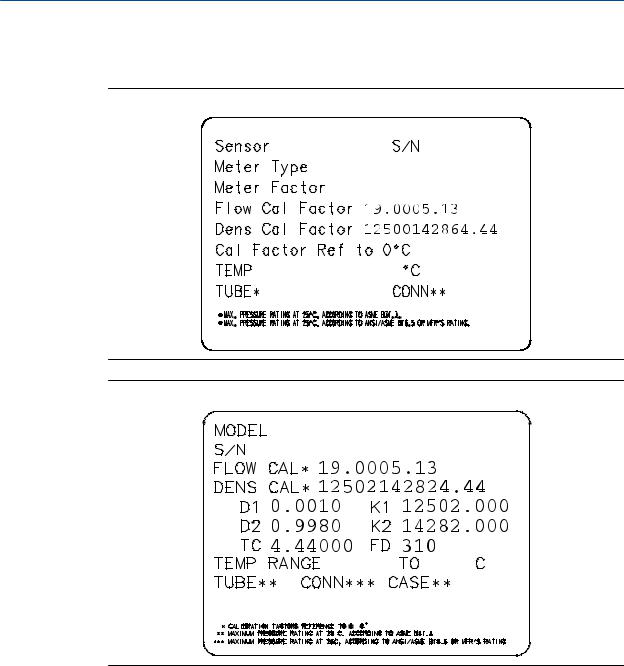
2.4.1Sample sensor tags
Figure 2-1: Tag on older curved-tube sensors (all sensors except T-Series)
Figure 2-2: Tag on newer curved-tube sensors (all sensors except T-Series)
Configuration and Use Manual |
9 |

Quick start
Figure 2-3: Tag on older straight-tube sensor (T-Series)
Figure 2-4: Tag on newer straight-tube sensor (T-Series)
2.4.2Flow calibration parameters (FCF, FT)
Two separate values are used to describe flow calibration: a 6-character FCF value and a 4- character FT value. They are provided on the sensor tag.
Both values contain decimal points. During characterization, these may be entered as two values or as a single 10-character string. The 10-character string is called either Flowcal or
FCF.
If your sensor tag shows the FCF and the FT values separately and you need to enter a single value, concatenate the two values to form the single parameter value.
If your sensor tag shows a concatenated Flowcal or FCF value and you need to enter the FCF and the FT values separately, split the concatenated value:
•FCF = The first 6 characters, including the decimal point
•FT = The last 4 characters, including the decimal point
10 |
Micro Motion® Model 1700 Transmitters with Analog Outputs |

Quick start
Example: Concatenating FCF and FT
FCF = x.xxxx
FT = y.yy
Flow calibration parameter: x.xxxxy.yy
Example: Splitting the concatenated Flowcal or FCF value
Flow calibration parameter: x.xxxxy.yy
FCF = x.xxxx
FT = y.yy
2.4.3Density calibration parameters (D1, D2, K1, K2, FD, DT,
TC)
Density calibration parameters are typically on the sensor tag and the calibration certificate.
If your sensor tag does not show a D1 or D2 value:
•For D1, enter the Dens A or D1 value from the calibration certificate. This value is the
line-condition density of the low-density calibration fluid. Micro Motion uses air. If you cannot find a Dens A or D1 value, enter 0.001 g/cm3.
•For D2, enter the Dens B or D2 value from the calibration certificate. This value is the
line-condition density of the high-density calibration fluid. Micro Motion uses water. If you cannot find a Dens B or D2 value, enter 0.998 g/cm3.
If your sensor tag does not show a K1 or K2 value:
•For K1, enter the first 5 digits of the density calibration factor. In the sample tag, this value is shown as 12500.
•For K2, enter the second 5 digits of the density calibration factor. In the sample tag, this value is shown as 14286.
If your sensor does not show an FD value, contact Micro Motion customer service.
If your sensor tag does not show a DT or TC value, enter the last 3 digits of the density calibration factor. In the sample tag, this value is shown as 4.44.
2.5Verify mass flow measurement
Check to see that the mass flow rate reported by the transmitter is accurate. You can use any available method.
•Read the value for Mass Flow Rate on the transmitter display.
•Connect to the transmitter with ProLink II and read the value for Mass Flow Rate in the Process Variables window (ProLink > Process Variables).
•Connect to the transmitter with ProLink III and read the value for Mass Flow Rate in the Process Variables panel.
Configuration and Use Manual |
11 |

Quick start
•Connect to the transmitter with the Field Communicator and read the value for Mass Flow Rate in the Process Variables menu (On-Line Menu > Overview > Primary Purpose Variables).
Postrequisites
If the reported mass flow rate is not accurate:
•Check the characterization parameters.
•Review the troubleshooting suggestions for flow measurement issues. See
Section 10.3.
2.6Verify the zero
Verifying the zero helps you determine if the stored zero value is appropriate to your installation, or if a field zero can improve measurement accuracy.
The zero verification procedure analyzes the Live Zero value under conditions of zero flow, and compares it to the Zero Stability range for the sensor. If the average Live Zero value is within a reasonable range, the zero value stored in the transmitter is valid. Performing a field calibration will not improve measurement accuracy.
2.6.1Verify the zero using ProLink II
Verifying the zero helps you determine if the stored zero value is appropriate to your installation, or if a field zero can improve measurement accuracy.
Important
In most cases, the factory zero is more accurate than the field zero. Do not zero the flowmeter unless one of the following is true:
•The zero is required by site procedures.
•The stored zero value fails the zero verification procedure.
Prerequisites
ProLink II v2.94 or later
Important
Do not verify the zero or zero the flowmeter if a high-severity alarm is active. Correct the problem, then verify the zero or zero the flowmeter. You may verify the zero or zero the flowmeter if a lowseverity alarm is active.
Procedure
1.Prepare the flowmeter:
a. Allow the flowmeter to warm up for at least 20 minutes after applying power.
12 |
Micro Motion® Model 1700 Transmitters with Analog Outputs |

Quick start
b.Run the process fluid through the sensor until the sensor temperature reaches the normal process operating temperature.
c.Stop flow through the sensor by shutting the downstream valve, and then the upstream valve if available.
d.Verify that the sensor is blocked in, that flow has stopped, and that the sensor is completely full of process fluid.
2.Choose ProLink > Calibration > Zero Verification and Calibration > Verify Zero and wait until the procedure completes.
3.If the zero verification procedure fails:
a.Confirm that the sensor is completely blocked in, that flow has stopped, and that the sensor is completely full of process fluid.
b.Verify that the process fluid is not flashing or condensing, and that it does not contain particles that can settle out.
c.Repeat the zero verification procedure.
d.If it fails again, zero the flowmeter.
For instructions on zeroing the flowmeter, see Zero the flowmeter.
Postrequisites
Restore normal flow through the sensor by opening the valves.
2.6.2Verify the zero using ProLink III
Verifying the zero helps you determine if the stored zero value is appropriate to your installation, or if a field zero can improve measurement accuracy.
Important
In most cases, the factory zero is more accurate than the field zero. Do not zero the flowmeter unless one of the following is true:
•The zero is required by site procedures.
•The stored zero value fails the zero verification procedure.
Prerequisites
ProLink III v1.0 with Patch Build 31, or a later release
Important
Do not verify the zero or zero the flowmeter if a high-severity alarm is active. Correct the problem, then verify the zero or zero the flowmeter. You may verify the zero or zero the flowmeter if a lowseverity alarm is active.
Procedure
1.Prepare the flowmeter:
a. Allow the flowmeter to warm up for at least 20 minutes after applying power.
Configuration and Use Manual |
13 |

Quick start
b.Run the process fluid through the sensor until the sensor temperature reaches the normal process operating temperature.
c.Stop flow through the sensor by shutting the downstream valve, and then the upstream valve if available.
d.Verify that the sensor is blocked in, that flow has stopped, and that the sensor is completely full of process fluid.
2.Choose Device Tools > Device Calibration > Zero Verification and Calibration > Verify Zero and wait until the procedure completes.
3.If the zero verification procedure fails:
a.Confirm that the sensor is completely blocked in, that flow has stopped, and that the sensor is completely full of process fluid.
b.Verify that the process fluid is not flashing or condensing, and that it does not contain particles that can settle out.
c.Repeat the zero verification procedure.
d.If it fails again, zero the flowmeter.
For instructions on zeroing the flowmeter, see Zero the flowmeter.
Postrequisites
Restore normal flow through the sensor by opening the valves.
2.6.3Terminology used with zero verification and zero calibration
Table 2-2: Terminology used with zero verification and zero calibration
Term |
Definition |
|
|
Zero |
In general, the offset required to synchronize the left pickoff and the right pickoff under |
|
conditions of zero flow. Unit = microseconds. |
|
|
Factory Zero |
The zero value obtained at the factory, under laboratory conditions. |
|
|
Field Zero |
The zero value obtained by performing a zero calibration outside the factory. |
|
|
Prior Zero |
The zero value stored in the transmitter at the time a field zero calibration is begun. May |
|
be the factory zero or a previous field zero. |
|
|
Manual Zero |
The zero value stored in the transmitter, typically obtained from a zero calibration proce- |
|
dure. It may also be configured manually. Also called “mechanical zero” or “stored zero.” |
|
|
Live Zero |
The real-time bidirectional mass flow rate with no flow damping or mass flow cutoff ap- |
|
plied. An adaptive damping value is applied only when the mass flow rate changes dra- |
|
matically over a very short interval. Unit = configured mass flow measurement unit. |
|
|
Zero Stability |
A laboratory-derived value used to calculate the expected accuracy for a sensor. Under |
|
laboratory conditions at zero flow, the average flow rate is expected to fall within the |
|
range defined by the Zero Stability value (0 ± Zero Stability). Each sensor size and model |
|
has a unique Zero Stability value. Statistically, 95% of all data points should fall within the |
|
range defined by the Zero Stability value. |
|
|
Zero Calibration |
The procedure used to determine the zero value. |
|
|
14 |
Micro Motion® Model 1700 Transmitters with Analog Outputs |
Quick start
Table 2-2: Terminology used with zero verification and zero calibration (continued)
Term |
Definition |
|
|
Zero Time |
The time period over which the Zero Calibration procedure is performed. Unit = seconds. |
|
|
Field Verification Zero |
A 3-minute running average of the Live Zero value, calculated by the transmitter. Unit = |
|
configured mass flow measurement unit. |
|
|
Zero Verification |
A procedure used to evaluate the stored zero and determine whether or not a field zero |
|
can improve measurement accuracy. |
|
|
Configuration and Use Manual |
15 |

Configuration and commissioning
Part II
Configuration and commissioning
Chapters covered in this part:
•Introduction to configuration and commissioning
•Configure process measurement
•Configure device options and preferences
•Integrate the meter with the control system
•Completing the configuration
16 |
Micro Motion® Model 1700 Transmitters with Analog Outputs |

Introduction to configuration and commissioning
3 Introduction to configuration and commissioning
Topics covered in this chapter:
•Configuration flowchart
•Default values and ranges
•Enable access to the off-line menu of the display
•Disable write-protection on the transmitter configuration
•Restore the factory configuration
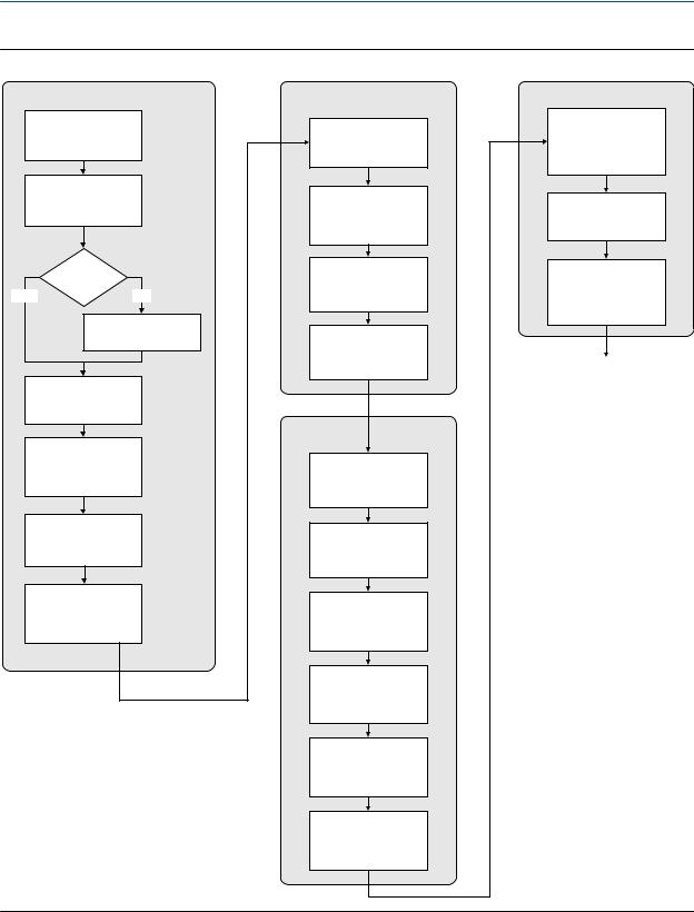
3.1Configuration flowchart
Use the following flowchart as a general guide to the configuration and commissioning process.
Some options may not apply to your installation. Detailed information is provided in the remainder of this manual. If you are using the Weights & Measures application, additional configuration and setup are required.
Configuration and Use Manual |
17 |
Introduction to configuration and commissioning
Figure 3-1: Configuration flowchart
Configure process measurement
Configure mass flow measurement
Configure volume flow meaurement
Volume flow type
Liquid |
Gas |
Define gas properties
Configure flow direction
Configure density measurement
Configure temperature measurement
Configure pressure compensation (optional)
Configure device options and preferences
Configure display parameters
Configure fault handling parameters
Configure sensor parameters
Configure device parameters
Integrate device with control system
Configure the channels
Configure the mA
output(s)
Configure the frequency output(s)
Configure the discrete output(s)
Configure events
Configure digital communications
Test and move to production
Test or tune transmitter using sensor simulation
Back up transmitter configuration
Enable write-protection on transmitter configuration
Done
18 |
Micro Motion® Model 1700 Transmitters with Analog Outputs |

Introduction to configuration and commissioning
3.2Default values and ranges
See Section F.1 to view the default values and ranges for the most commonly used parameters.
3.3Enable access to the off-line menu of the display
Display (standard) |
OFF-LINE MAINT > OFF-LINE CONFG > DISPLAY |
|
|
Chinese-language |
Offline Maintain > Configuration > Display |
display |
|
|
|
ProLink II |
ProLink > Configuration > Display > Display Options |
|
|
ProLink III |
Device Tools > Configuration > Transmitter Display > Display Security |
|
|
Field Communicator |
Configure > Manual Setup > Display > Offline Variable Menu Features |
|
|
Overview
By default, access to the off-line menu of the display is enabled. If it is disabled, you must enable it if you want to use the display to configure the transmitter.
Restriction
You cannot use the display to enable access to the off-line menu. You must make a connection from another tool.
3.4Disable write-protection on the transmitter configuration
Display (standard) |
OFF-LINE MAINT > CONFG > LOCK |
|
|
Chinese-language |
Offline Maintain > Configuration > Lock |
display |
|
|
|
ProLink II |
ProLink > Configuration > Device > Enable Write Protection |
|
|
ProLink III |
Device Tools > Configuration > Write-Protection |
|
|
Field Communicator |
Configure > Manual Setup > Info Parameters > Transmitter Info > Write Protect |
|
|
Overview
If the transmitter is write-protected, the configuration is locked and you must unlock it before you can change any configuration parameters. By default, the transmitter is not write-protected.
Configuration and Use Manual |
19 |

Introduction to configuration and commissioning
Tip
Write-protecting the transmitter prevents accidental changes to configuration. It does not prevent normal operational use. You can always disable write-protection, perform any required configuration changes, then re-enable write-protection.
3.5Restore the factory configuration
Display (standard) |
Not available |
|
|
Chinese-language |
Not available |
display |
|
|
|
ProLink II |
ProLink > Configuration > Device > Restore Factory Configuration |
|
|
ProLink III |
Device Tools > Configuration Transfer > Restore Factory Configuration |
|
|
Field Communicator |
Not available |
|
|
Overview
Restoring the factory configuration returns the transmitter to a known operational configuration. This may be useful if you experience problems during configuration.
Tip
Restoring the factory configuration is not a common action. You may want to contact Micro Motion to see if there is a preferred method to resolve any issues.
20 |
Micro Motion® Model 1700 Transmitters with Analog Outputs |

Configure process measurement
4 Configure process measurement
Topics covered in this chapter:
•Configure mass flow measurement
•Configure volume flow measurement for liquid applications
•Configure gas standard volume (GSV) flow measurement
•Configure Flow Direction
•Configure density measurement
•Configure temperature measurement
•Configure pressure compensation
4.1Configure mass flow measurement
The mass flow measurement parameters control how mass flow is measured and reported.
The mass flow measurement parameters include:
•Mass Flow Measurement Unit
•Flow Damping
•Mass Flow Cutoff
4.1.1Configure Mass Flow Measurement Unit
Display (standard) |
OFF-LINE MAINT > OFF-LINE CONFG > UNITS > MASS |
|
|
Chinese-language |
Offline Maintain > Configuration > Units > Mass Flow Rate |
display |
|
|
|
ProLink II |
ProLink > Configuration > Flow > Mass Flow Unit |
|
|
ProLink III |
Device Tools > Configuration > Process Measurement > Flow |
|
|
Field Communicator |
Configure > Manual Setup > Measurements > Flow > Mass Flow Unit |
|
|
Overview
Mass Flow Measurement Unit specifies the unit of measure that will be used for the mass flow rate. The unit used for mass total and mass inventory is derived from this unit.
Procedure
Set Mass Flow Measurement Unit to the unit you want to use.
The default setting for Mass Flow Measurement Unit is g/sec (grams per second).
Configuration and Use Manual |
21 |

Configure process measurement
Tip
If the measurement unit you want to use is not available, you can define a special measurement unit.
Options for Mass Flow Measurement Unit
The transmitter provides a standard set of measurement units for Mass Flow Measurement Unit, plus one user-defined special measurement unit. Different communications tools may use different labels for the units.
Table 4-1: Options for Mass Flow Measurement Unit
|
|
|
Label |
|
|
|
|
|
|
|
|
|
Display (stand- |
Chinese-lan- |
ProLink II |
ProLink III |
Field Commu- |
Unit description |
ard) |
guage display |
|
|
nicator |
|
|
|
|
|
|
Grams per second |
G/S |
g/sec |
g/sec |
g/sec |
g/s |
|
|
|
|
|
|
Grams per minute |
G/MIN |
g/min |
g/min |
g/min |
g/min |
|
|
|
|
|
|
Grams per hour |
G/H |
g/hr |
g/hr |
g/hr |
g/h |
|
|
|
|
|
|
Kilograms per second |
KG/S |
kg/sec |
kg/sec |
kg/sec |
kg/s |
|
|
|
|
|
|
Kilograms per minute |
KG/MIN |
kg/min |
kg/min |
kg/min |
kg/min |
|
|
|
|
|
|
Kilograms per hour |
KG/H |
kg/hr |
kg/hr |
kg/hr |
kg/h |
|
|
|
|
|
|
Kilograms per day |
KG/D |
kg/day |
kg/day |
kg/day |
kg/d |
|
|
|
|
|
|
Metric tons per minute |
T/MIN |
mTon/min |
mTon/min |
mTon/min |
MetTon/min |
|
|
|
|
|
|
Metric tons per hour |
T/H |
mTon/hr |
mTon/hr |
mTon/hr |
MetTon/h |
|
|
|
|
|
|
Metric tons per day |
T/D |
mTon/day |
mTon/day |
mTon/day |
MetTon/d |
|
|
|
|
|
|
Pounds per second |
LB/S |
lbs/sec |
lbs/sec |
lbs/sec |
lb/s |
|
|
|
|
|
|
Pounds per minute |
LB/MIN |
lbs/min |
lbs/min |
lbs/min |
lb/min |
|
|
|
|
|
|
Pounds per hour |
LB/H |
lbs/hr |
lbs/hr |
lbs/hr |
lb/h |
|
|
|
|
|
|
Pounds per day |
LB/D |
lbs/day |
lbs/day |
lbs/day |
lb/d |
|
|
|
|
|
|
Short tons (2000 pounds) |
ST/MIN |
sTon/min |
sTon/min |
sTon/min |
STon/min |
per minute |
|
|
|
|
|
|
|
|
|
|
|
Short tons (2000 pounds) |
ST/H |
sTon/hr |
sTon/hr |
sTon/hr |
STon/h |
per hour |
|
|
|
|
|
|
|
|
|
|
|
Short tons (2000 pounds) |
ST/D |
sTon/day |
sTon/day |
sTon/day |
STon/d |
per day |
|
|
|
|
|
|
|
|
|
|
|
Long tons (2240 pounds) |
LT/H |
lTon/hr |
lTon/hr |
lTon/hr |
LTon/h |
per hour |
|
|
|
|
|
|
|
|
|
|
|
Long tons (2240 pounds) |
LT/D |
lTon/day |
lTon/day |
lTon/day |
LTon/d |
per day |
|
|
|
|
|
|
|
|
|
|
|
Special unit |
SPECL |
Special |
special |
special |
Spcl |
|
|
|
|
|
|
22 |
Micro Motion® Model 1700 Transmitters with Analog Outputs |

Configure process measurement
Define a special measurement unit for mass flow
Display (standard) |
Not available |
|
|
Chinese-language |
Offline Maintain > Configuration > Units > Special Mass Flow |
display |
|
|
|
ProLink II |
ProLink > Configuration > Special Units |
|
|
ProLink III |
Device Tools > Configuration > Process Measurement > Flow > Special Units |
|
|
Field Communicator |
Configure > Manual Setup > Measurements > Special Units > Mass Special Units |
|
|
Overview
A special measurement unit is a user-defined unit of measure that allows you to report process data, totalizer data, and inventory data in a unit that is not available in the transmitter. A special measurement unit is calculated from an existing measurement unit using a conversion factor.
Note
Although you cannot define a special measurement unit using the display (standard option), you can use the standard display to select an existing special measurement unit, and to view process data using the special measurement unit.
Procedure
1.Specify Base Mass Unit.
Base Mass Unit is the existing mass unit that the special unit will be based on.
2.Specify Base Time Unit.
Base Time Unit is the existing time unit that the special unit will be based on.
3.Calculate Mass Flow Conversion Factor as follows:
a.x base units = y special units
b.Mass Flow Conversion Factor = x/y
4.Enter Mass Flow Conversion Factor.
5.Set Mass Flow Label to the name you want to use for the mass flow unit.
6.Set Mass Total Label to the name you want to use for the mass total and mass inventory unit.
The special measurement unit is stored in the transmitter. You can configure the transmitter to use the special measurement unit at any time.
Example: Defining a special measurement unit for mass flow
You want to measure mass flow in ounces per second (oz/sec).
1.Set Base Mass Unit to Pounds (lb).
2.Set Base Time Unit to Seconds (sec).
Configuration and Use Manual |
23 |

Configure process measurement
3.Calculate Mass Flow Conversion Factor:
a.1 lb/sec = 16 oz/sec
b.Mass Flow Conversion Factor = 1/16 = 0.0625
4.Set Mass Flow Conversion Factor to 0.0625.
5.Set Mass Flow Label to oz/sec.
6.Set Mass Total Label to oz.
4.1.2Configure Flow Damping
Display (standard) |
Not available |
|
|
Chinese-language |
Offline Maintain > Configuration > Damping > Mass Flow Damping |
display |
|
|
|
ProLink II |
ProLink > Configuration > Flow > Flow Damp |
|
|
ProLink III |
Device Tools > Configuration > Process Measurement > Flow |
|
|
Field Communicator |
Configure > Manual Setup > Measurements > Flow > Flow Damping |
|
|
Overview
Damping is used to smooth out small, rapid fluctuations in process measurement. Damping Value specifies the time period (in seconds) over which the transmitter will spread changes in the reported process variable. At the end of the interval, the reported process variable will reflect 63% of the change in the actual measured value.
Procedure
Set Flow Damping to the value you want to use.
The default value is 0.8 seconds. The range depends on the core processor type and the setting of Update Rate, as shown in the following table.
Core processor type |
Update Rate setting |
Flow Damping range |
Standard |
Normal |
0 to 51.2 seconds |
|
|
|
|
Special |
0 to 10.24 seconds |
|
|
|
Enhanced |
Not applicable |
0 to 51.2 seconds |
|
|
|
Tips
•A high damping value makes the process variable appear smoother because the reported value changes slowly.
•A low damping value makes the process variable appear more erratic because the reported value changes more quickly.
•The combination of a high damping value and rapid, large changes in flow rate can result in increased measurement error.
24 |
Micro Motion® Model 1700 Transmitters with Analog Outputs |
Loading...