


MSP400RH
Table of contents
 Loading...
Reference Manual
IP2048/RM, Rev AA
February 2015
Mobrey MSP400RH and MSP900GH
Ultrasonic Liquid Level Transmitters


Reference Manual
IP2048/RM, Rev AA
Title Page
February 2015
Mobrey MSP400RH and MSP900GH
Ultrasonic Liquid Level Transmitters
Read this manual before working with the product. For personal and system safety, and for
optimum product performance, make sure you thoroughly understand the contents before
installing, using, or maintaining this product.
The products described in this document are NOT designed for nuclear-qualified
applications.
Using non-nuclear qualified products in applications that require nuclear-qualified
hardware or products may cause inaccurate readings.
For information on nuclear-qualified products, contact your local Rosemount Measurement
sales representative.
This device complies with part 15 of the FCC rules. Operation is subject to the following two
conditions: (1) This device may not cause harmful interference, and (2) this device must
accept any interference received, including interference that may cause undesired
operation.


TOC-1
Reference Manual
IP2048/RM, Rev AA
Table of Contents
February 2015
Tab le of C ontents
Table of Contents
1Section 1: Introduction
1.1 Safety messages. . . . . . . . . . . . . . . . . . . . . . . . . . . . . . . . . . . . . . . . . . . . . . . . . . . . . . . .1
1.2 Manual overview . . . . . . . . . . . . . . . . . . . . . . . . . . . . . . . . . . . . . . . . . . . . . . . . . . . . . . .2
1.3 Service and product support . . . . . . . . . . . . . . . . . . . . . . . . . . . . . . . . . . . . . . . . . . . . .2
1.4 Product recycling/disposal . . . . . . . . . . . . . . . . . . . . . . . . . . . . . . . . . . . . . . . . . . . . . . .2
2Section 2: Transmitter Overview
2.1 Introduction to the transmitters . . . . . . . . . . . . . . . . . . . . . . . . . . . . . . . . . . . . . . . . . .3
2.2 Theory of operation . . . . . . . . . . . . . . . . . . . . . . . . . . . . . . . . . . . . . . . . . . . . . . . . . . . . .3
2.3 Components of the transmitter . . . . . . . . . . . . . . . . . . . . . . . . . . . . . . . . . . . . . . . . . .4
2.4 System architecture. . . . . . . . . . . . . . . . . . . . . . . . . . . . . . . . . . . . . . . . . . . . . . . . . . . . .4
3Section 3: Installation
3.1 Safety messages. . . . . . . . . . . . . . . . . . . . . . . . . . . . . . . . . . . . . . . . . . . . . . . . . . . . . . . .7
3.2 Considerations before installation . . . . . . . . . . . . . . . . . . . . . . . . . . . . . . . . . . . . . . . .8
3.2.1 Safety considerations . . . . . . . . . . . . . . . . . . . . . . . . . . . . . . . . . . . . . . . . . . . . 8
3.3 Mechanical installation . . . . . . . . . . . . . . . . . . . . . . . . . . . . . . . . . . . . . . . . . . . . . . . . . .9
3.3.1 Consider the liquid surface conditions. . . . . . . . . . . . . . . . . . . . . . . . . . . . .10
3.3.2 In-tank effects. . . . . . . . . . . . . . . . . . . . . . . . . . . . . . . . . . . . . . . . . . . . . . . . . .10
3.3.3 Mounting the transmitter above the liquid surface. . . . . . . . . . . . . . . . . .11
3.3.4 Open channel flow installations . . . . . . . . . . . . . . . . . . . . . . . . . . . . . . . . . .13
3.4 Electrical installation . . . . . . . . . . . . . . . . . . . . . . . . . . . . . . . . . . . . . . . . . . . . . . . . . . 16
3.4.1 Connecting the cable(s) to the transmitter . . . . . . . . . . . . . . . . . . . . . . . .16
3.4.2 Connecting the cable wires to the MSP400RH. . . . . . . . . . . . . . . . . . . . . .17
3.4.3 Connecting the cable wires to the MSP900GH. . . . . . . . . . . . . . . . . . . . . .18
3.4.4 Remote temperature sensor . . . . . . . . . . . . . . . . . . . . . . . . . . . . . . . . . . . . .19
3.4.5 Wiring to allow HART communications. . . . . . . . . . . . . . . . . . . . . . . . . . . .19
3.4.6 Lightning / Surge protection and other loop devices . . . . . . . . . . . . . . . .20
4Section 4: Starting up
4.1 Overview . . . . . . . . . . . . . . . . . . . . . . . . . . . . . . . . . . . . . . . . . . . . . . . . . . . . . . . . . . . . 21
4.1.1 Display and push-buttons. . . . . . . . . . . . . . . . . . . . . . . . . . . . . . . . . . . . . . . .21
4.1.2 Power up . . . . . . . . . . . . . . . . . . . . . . . . . . . . . . . . . . . . . . . . . . . . . . . . . . . . . .22
4.1.3 Before programming. . . . . . . . . . . . . . . . . . . . . . . . . . . . . . . . . . . . . . . . . . . .23

TOC-2
Reference Manual
IP2048/RM, Rev AA
Table of Contents
February 2015
Table of Contents
4.2 Programming . . . . . . . . . . . . . . . . . . . . . . . . . . . . . . . . . . . . . . . . . . . . . . . . . . . . . . . . 23
4.2.1 Overview . . . . . . . . . . . . . . . . . . . . . . . . . . . . . . . . . . . . . . . . . . . . . . . . . . . . . .23
4.2.2 Selecting the duty . . . . . . . . . . . . . . . . . . . . . . . . . . . . . . . . . . . . . . . . . . . . . .24
4.2.3 Selecting the units of measurement . . . . . . . . . . . . . . . . . . . . . . . . . . . . . .25
4.2.4 Setting the correct bottom reference . . . . . . . . . . . . . . . . . . . . . . . . . . . . .26
4.2.5 Selecting a profile . . . . . . . . . . . . . . . . . . . . . . . . . . . . . . . . . . . . . . . . . . . . . .27
4.2.6 Power Factor for the Flow Law. . . . . . . . . . . . . . . . . . . . . . . . . . . . . . . . . . . .31
4.2.7 K-factor for the flow law . . . . . . . . . . . . . . . . . . . . . . . . . . . . . . . . . . . . . . . . .32
4.2.8 Maximum level entry. . . . . . . . . . . . . . . . . . . . . . . . . . . . . . . . . . . . . . . . . . . .33
4.2.9 Maximum flow entry . . . . . . . . . . . . . . . . . . . . . . . . . . . . . . . . . . . . . . . . . . . .34
4.2.10 Maximum contents (volume) entry . . . . . . . . . . . . . . . . . . . . . . . . . . . . . . .35
4.2.11 Setting the 4 mA point . . . . . . . . . . . . . . . . . . . . . . . . . . . . . . . . . . . . . . . . . .36
4.2.12 Setting the 20 mA point . . . . . . . . . . . . . . . . . . . . . . . . . . . . . . . . . . . . . . . . .37
4.2.13 Setting the output damping . . . . . . . . . . . . . . . . . . . . . . . . . . . . . . . . . . . . .38
4.2.14 Selecting the alarm condition action . . . . . . . . . . . . . . . . . . . . . . . . . . . . . .39
4.2.15 Setting the relay on and off points (MSP400RH) . . . . . . . . . . . . . . . . . . . .40
4.2.16 Setting the 4 and 20 mA levels using ranging. . . . . . . . . . . . . . . . . . . . . . .41
4.3 Final checks . . . . . . . . . . . . . . . . . . . . . . . . . . . . . . . . . . . . . . . . . . . . . . . . . . . . . . . . . . 43
4.4 Power failure . . . . . . . . . . . . . . . . . . . . . . . . . . . . . . . . . . . . . . . . . . . . . . . . . . . . . . . . . 43
5Section 5: Service and Troubleshooting
5.1 Safety messages. . . . . . . . . . . . . . . . . . . . . . . . . . . . . . . . . . . . . . . . . . . . . . . . . . . . . . 45
5.2 Servicing . . . . . . . . . . . . . . . . . . . . . . . . . . . . . . . . . . . . . . . . . . . . . . . . . . . . . . . . . . . . 46
5.3 Diagnostics . . . . . . . . . . . . . . . . . . . . . . . . . . . . . . . . . . . . . . . . . . . . . . . . . . . . . . . . . . 46
5.3.1 General troubleshooting . . . . . . . . . . . . . . . . . . . . . . . . . . . . . . . . . . . . . . . .46
5.3.2 Diagnostic data . . . . . . . . . . . . . . . . . . . . . . . . . . . . . . . . . . . . . . . . . . . . . . . .46
5.3.3 Loop test . . . . . . . . . . . . . . . . . . . . . . . . . . . . . . . . . . . . . . . . . . . . . . . . . . . . . .47
5.4 Engineering menu . . . . . . . . . . . . . . . . . . . . . . . . . . . . . . . . . . . . . . . . . . . . . . . . . . . . 49
5.4.1 Accessing the engineering menu . . . . . . . . . . . . . . . . . . . . . . . . . . . . . . . . .49
5.4.2 Setting the threshold . . . . . . . . . . . . . . . . . . . . . . . . . . . . . . . . . . . . . . . . . . .49
5.4.3 Setting lost echo time. . . . . . . . . . . . . . . . . . . . . . . . . . . . . . . . . . . . . . . . . . .50
5.4.4 Setting the dead band. . . . . . . . . . . . . . . . . . . . . . . . . . . . . . . . . . . . . . . . . . .51
5.4.5 Setting the frequency . . . . . . . . . . . . . . . . . . . . . . . . . . . . . . . . . . . . . . . . . . .52
5.4.6 Setting the pulse repetition frequency . . . . . . . . . . . . . . . . . . . . . . . . . . . .53
5.4.7 Setting valid echo count. . . . . . . . . . . . . . . . . . . . . . . . . . . . . . . . . . . . . . . . .54
5.4.8 Setting Spike Rejection. . . . . . . . . . . . . . . . . . . . . . . . . . . . . . . . . . . . . . . . . .55
5.4.9 Learn about echoes from false targets. . . . . . . . . . . . . . . . . . . . . . . . . . . . .56
5.4.10 Setting the ambient temperature. . . . . . . . . . . . . . . . . . . . . . . . . . . . . . . . .57

TOC-3
Reference Manual
IP2048/RM, Rev AA
Table of Contents
February 2015
Tab le of C ontents
5.4.11 Temperature calibration. . . . . . . . . . . . . . . . . . . . . . . . . . . . . . . . . . . . . . . . .58
5.4.12 Loading factory default values. . . . . . . . . . . . . . . . . . . . . . . . . . . . . . . . . . . .59
5.4.13 Changing the base units . . . . . . . . . . . . . . . . . . . . . . . . . . . . . . . . . . . . . . . . .60
5.5 False echoes under certain ambient operating conditions. . . . . . . . . . . . . . . . . . 61
6Section A: Reference Data
A.1 Specifications . . . . . . . . . . . . . . . . . . . . . . . . . . . . . . . . . . . . . . . . . . . . . . . . . . . . . . . . 63
A.1.1 General . . . . . . . . . . . . . . . . . . . . . . . . . . . . . . . . . . . . . . . . . . . . . . . . . . . . . . .63
A.1.2 Measuring performance . . . . . . . . . . . . . . . . . . . . . . . . . . . . . . . . . . . . . . . . .63
A.1.3 Display and configuration . . . . . . . . . . . . . . . . . . . . . . . . . . . . . . . . . . . . . . .63
A.1.4 Electrical . . . . . . . . . . . . . . . . . . . . . . . . . . . . . . . . . . . . . . . . . . . . . . . . . . . . . .64
A.1.5 Physical specifications. . . . . . . . . . . . . . . . . . . . . . . . . . . . . . . . . . . . . . . . . . .65
A.1.6 Mechanical . . . . . . . . . . . . . . . . . . . . . . . . . . . . . . . . . . . . . . . . . . . . . . . . . . . .65
A.1.7 Measuring . . . . . . . . . . . . . . . . . . . . . . . . . . . . . . . . . . . . . . . . . . . . . . . . . . . . .65
A.1.8 Environment . . . . . . . . . . . . . . . . . . . . . . . . . . . . . . . . . . . . . . . . . . . . . . . . . . .66
A.2 Dimension drawings . . . . . . . . . . . . . . . . . . . . . . . . . . . . . . . . . . . . . . . . . . . . . . . . . . 68
7Section B: Product Certifications
B.1 Safety messages. . . . . . . . . . . . . . . . . . . . . . . . . . . . . . . . . . . . . . . . . . . . . . . . . . . . . . 71
B.2 Approved manufacturing location . . . . . . . . . . . . . . . . . . . . . . . . . . . . . . . . . . . . . . 71
B.3 European directive information. . . . . . . . . . . . . . . . . . . . . . . . . . . . . . . . . . . . . . . . . 72
B.4 Ordinary locations certification (MSP400RH only). . . . . . . . . . . . . . . . . . . . . . . . . 72
B.4.1 American certification. . . . . . . . . . . . . . . . . . . . . . . . . . . . . . . . . . . . . . . . . . .72
B.5 Hazardous locations certifications (MSP900GH only). . . . . . . . . . . . . . . . . . . . . . 72
B.5.1 European certification. . . . . . . . . . . . . . . . . . . . . . . . . . . . . . . . . . . . . . . . . . .72
8Section C: Integrated Display Menus
C.1 Main menu map . . . . . . . . . . . . . . . . . . . . . . . . . . . . . . . . . . . . . . . . . . . . . . . . . . . . . . 76
C.2 Diagnostics menu map . . . . . . . . . . . . . . . . . . . . . . . . . . . . . . . . . . . . . . . . . . . . . . . . 78
C.3 Engineering menu map. . . . . . . . . . . . . . . . . . . . . . . . . . . . . . . . . . . . . . . . . . . . . . . . 79
AAppendix D: Mobrey MCU900 Series
D.1 Introduction . . . . . . . . . . . . . . . . . . . . . . . . . . . . . . . . . . . . . . . . . . . . . . . . . . . . . . . . . 81
9Appendix E: Field Communicator
E.1 Introduction . . . . . . . . . . . . . . . . . . . . . . . . . . . . . . . . . . . . . . . . . . . . . . . . . . . . . . . . . 85
E.2 Safety messages. . . . . . . . . . . . . . . . . . . . . . . . . . . . . . . . . . . . . . . . . . . . . . . . . . . . . . 85

TOC-4
Reference Manual
IP2048/RM, Rev AA
Table of Contents
February 2015
Table of Contents
10Appendix F: Configuring Using HART
F. 1 Overview . . . . . . . . . . . . . . . . . . . . . . . . . . . . . . . . . . . . . . . . . . . . . . . . . . . . . . . . . . . . 89
F. 2 Command parameters . . . . . . . . . . . . . . . . . . . . . . . . . . . . . . . . . . . . . . . . . . . . . . . . 90
F. 2 .1 Base units . . . . . . . . . . . . . . . . . . . . . . . . . . . . . . . . . . . . . . . . . . . . . . . . . . . . .90
F. 2 .2 Set as empty . . . . . . . . . . . . . . . . . . . . . . . . . . . . . . . . . . . . . . . . . . . . . . . . . . .91
F. 2 .3 Present depth . . . . . . . . . . . . . . . . . . . . . . . . . . . . . . . . . . . . . . . . . . . . . . . . . .92
F. 2 .4 Learn false echo . . . . . . . . . . . . . . . . . . . . . . . . . . . . . . . . . . . . . . . . . . . . . . . .93
F. 2 .5 Auto tank map . . . . . . . . . . . . . . . . . . . . . . . . . . . . . . . . . . . . . . . . . . . . . . . . .94
F. 2 .6 Simulation of PV. . . . . . . . . . . . . . . . . . . . . . . . . . . . . . . . . . . . . . . . . . . . . . . .95
F. 2 .7 Restart device. . . . . . . . . . . . . . . . . . . . . . . . . . . . . . . . . . . . . . . . . . . . . . . . . .96
F. 2 .8 Load defaults . . . . . . . . . . . . . . . . . . . . . . . . . . . . . . . . . . . . . . . . . . . . . . . . . .97
F. 2 .9 Simulate current output. . . . . . . . . . . . . . . . . . . . . . . . . . . . . . . . . . . . . . . . .98
F.2.10 Trim 4 mA / Trim 20 mA . . . . . . . . . . . . . . . . . . . . . . . . . . . . . . . . . . . . . . . . .99
F. 3 Configuration parameters . . . . . . . . . . . . . . . . . . . . . . . . . . . . . . . . . . . . . . . . . . . . 101
F. 3 .1 Message (P000) . . . . . . . . . . . . . . . . . . . . . . . . . . . . . . . . . . . . . . . . . . . . . . 101
F. 3 .2 Tag (P001). . . . . . . . . . . . . . . . . . . . . . . . . . . . . . . . . . . . . . . . . . . . . . . . . . . 102
F. 3 .3 Descriptor (P002). . . . . . . . . . . . . . . . . . . . . . . . . . . . . . . . . . . . . . . . . . . . . 102
F. 3 .4 Final assembly number (P004) . . . . . . . . . . . . . . . . . . . . . . . . . . . . . . . . . 103
F. 3 .5 Serial number (P005) . . . . . . . . . . . . . . . . . . . . . . . . . . . . . . . . . . . . . . . . . 104
F. 3 .6 Bottom reference (P010) . . . . . . . . . . . . . . . . . . . . . . . . . . . . . . . . . . . . . . 105
F. 3 .7 Upper blanking (P023) . . . . . . . . . . . . . . . . . . . . . . . . . . . . . . . . . . . . . . . . 107
F. 3 .8 Lower blanking (P063) . . . . . . . . . . . . . . . . . . . . . . . . . . . . . . . . . . . . . . . . 108
F. 3 .9 Distance offset (P060). . . . . . . . . . . . . . . . . . . . . . . . . . . . . . . . . . . . . . . . . 109
F.3.10 Level offset (P069). . . . . . . . . . . . . . . . . . . . . . . . . . . . . . . . . . . . . . . . . . . . 110
F.3.11 Tank shape / non-linear profile (P011). . . . . . . . . . . . . . . . . . . . . . . . . . . 111
F.3.12 Contents (volume) measurement . . . . . . . . . . . . . . . . . . . . . . . . . . . . . . 112
F.3.13 Flow measurement . . . . . . . . . . . . . . . . . . . . . . . . . . . . . . . . . . . . . . . . . . . 116
F.3.14 Primary variable units (P012). . . . . . . . . . . . . . . . . . . . . . . . . . . . . . . . . . . 120
F.3.15 Scale Factor / K-Factor (P013) . . . . . . . . . . . . . . . . . . . . . . . . . . . . . . . . . . 121
F.3.16 Profile height / Power factor (P014) . . . . . . . . . . . . . . . . . . . . . . . . . . . . . 122
F.3.17 Profile points 1 to 10 (P030 to P039) . . . . . . . . . . . . . . . . . . . . . . . . . . . . 124
F.3.18 Upper range value (P015). . . . . . . . . . . . . . . . . . . . . . . . . . . . . . . . . . . . . . 125
F.3.19 Lower range value (P016). . . . . . . . . . . . . . . . . . . . . . . . . . . . . . . . . . . . . . 126
F.3.20 Damping (P020). . . . . . . . . . . . . . . . . . . . . . . . . . . . . . . . . . . . . . . . . . . . . . 127
F.3.21 Setting-up relays on the MSP400RH . . . . . . . . . . . . . . . . . . . . . . . . . . . . 128
F.3.22 Relay 1 (P070 to P072) . . . . . . . . . . . . . . . . . . . . . . . . . . . . . . . . . . . . . . . . 128
F.3.23 Relay 2 (P073 to P075) . . . . . . . . . . . . . . . . . . . . . . . . . . . . . . . . . . . . . . . . 128

TOC-5
Reference Manual
IP2048/RM, Rev AA
Table of Contents
February 2015
Tab le of C ontents
F.3.24 Lost echo delay (P021) . . . . . . . . . . . . . . . . . . . . . . . . . . . . . . . . . . . . . . . . 128
F.3.25 Lost echo action (P022) . . . . . . . . . . . . . . . . . . . . . . . . . . . . . . . . . . . . . . . 130
F.3.26 Speed of sound (P024) . . . . . . . . . . . . . . . . . . . . . . . . . . . . . . . . . . . . . . . . 131
F.3.27 Temperature (P025) . . . . . . . . . . . . . . . . . . . . . . . . . . . . . . . . . . . . . . . . . . 132
F.3.28 Set threshold (P026) . . . . . . . . . . . . . . . . . . . . . . . . . . . . . . . . . . . . . . . . . . 133
F.3.29 Transmit power control (P040) . . . . . . . . . . . . . . . . . . . . . . . . . . . . . . . . . 135
F.3.30 Pulse repeat (P041) . . . . . . . . . . . . . . . . . . . . . . . . . . . . . . . . . . . . . . . . . . . 136
F.3.31 Echoes needed (P042) . . . . . . . . . . . . . . . . . . . . . . . . . . . . . . . . . . . . . . . . 136
F.3.32 Threshold 1 time (P043). . . . . . . . . . . . . . . . . . . . . . . . . . . . . . . . . . . . . . . 137
F.3.33 Threshold 1 size (P048). . . . . . . . . . . . . . . . . . . . . . . . . . . . . . . . . . . . . . . . 138
F.3.34 Target pulses (P044) . . . . . . . . . . . . . . . . . . . . . . . . . . . . . . . . . . . . . . . . . . 139
F.3.35 Target frequency (P045). . . . . . . . . . . . . . . . . . . . . . . . . . . . . . . . . . . . . . . 140
F.3.36 Spike rejection (P049). . . . . . . . . . . . . . . . . . . . . . . . . . . . . . . . . . . . . . . . . 141
F.3.37 False echo data (P081 to P088). . . . . . . . . . . . . . . . . . . . . . . . . . . . . . . . . 142
F.3.38 Clear false echoes (P089) . . . . . . . . . . . . . . . . . . . . . . . . . . . . . . . . . . . . . . 143
F.3.39 Transducer material (P970) . . . . . . . . . . . . . . . . . . . . . . . . . . . . . . . . . . . . 144
F.3.40 Poll address (D951) . . . . . . . . . . . . . . . . . . . . . . . . . . . . . . . . . . . . . . . . . . . 144
F.3.41 Maximum temperature (P046) . . . . . . . . . . . . . . . . . . . . . . . . . . . . . . . . . 145
F.3.42 Minimum temperature (P047) . . . . . . . . . . . . . . . . . . . . . . . . . . . . . . . . . 146
F.3.43 Date (P003). . . . . . . . . . . . . . . . . . . . . . . . . . . . . . . . . . . . . . . . . . . . . . . . . . 146
F. 4 Monitoring and diagnostic parameters . . . . . . . . . . . . . . . . . . . . . . . . . . . . . . . . . 147
F. 4 .1 Process value / Primary variable (PV) (D900) . . . . . . . . . . . . . . . . . . . . . 147
F. 4 .2 Level / Secondary variable (SV) (D901) . . . . . . . . . . . . . . . . . . . . . . . . . . 148
F. 4 .3 Distance / Tertiary variable (TV) (D902) . . . . . . . . . . . . . . . . . . . . . . . . . 149
F. 4 .4 Temperature / Fourth variable (FV) (D903). . . . . . . . . . . . . . . . . . . . . . . 150
F. 4 .5 % of output current (D905) . . . . . . . . . . . . . . . . . . . . . . . . . . . . . . . . . . . . 151
F. 4 .6 Current output (D906) . . . . . . . . . . . . . . . . . . . . . . . . . . . . . . . . . . . . . . . . 152
F. 4 .7 Distance (D910) . . . . . . . . . . . . . . . . . . . . . . . . . . . . . . . . . . . . . . . . . . . . . . 153
F. 4 .8 Echo size (D911). . . . . . . . . . . . . . . . . . . . . . . . . . . . . . . . . . . . . . . . . . . . . . 154
F. 4 .9 Echo success (D912) . . . . . . . . . . . . . . . . . . . . . . . . . . . . . . . . . . . . . . . . . . 155
F.4.10 Target echoes (D913) . . . . . . . . . . . . . . . . . . . . . . . . . . . . . . . . . . . . . . . . . 156
F.4.11 Speed of sound (D914) . . . . . . . . . . . . . . . . . . . . . . . . . . . . . . . . . . . . . . . . 157
F.4.12 Temperature for SoS calculation (D915). . . . . . . . . . . . . . . . . . . . . . . . . 158
F.4.13 Frequency (D916) . . . . . . . . . . . . . . . . . . . . . . . . . . . . . . . . . . . . . . . . . . . . 159
F.4.14 Threshold in use (D917) . . . . . . . . . . . . . . . . . . . . . . . . . . . . . . . . . . . . . . . 160
F.4.15 Pulses in use (D918) . . . . . . . . . . . . . . . . . . . . . . . . . . . . . . . . . . . . . . . . . . 161
F.4.16 Transmit power (D919) . . . . . . . . . . . . . . . . . . . . . . . . . . . . . . . . . . . . . . . 162

TOC-6
Reference Manual
IP2048/RM, Rev AA
Table of Contents
February 2015
Table of Contents
F.4.17 Model code (D949) . . . . . . . . . . . . . . . . . . . . . . . . . . . . . . . . . . . . . . . . . . . 163
F.4.18 Hardware rev. (D952) . . . . . . . . . . . . . . . . . . . . . . . . . . . . . . . . . . . . . . . . . 163
F.4.19 Software revision (D953) . . . . . . . . . . . . . . . . . . . . . . . . . . . . . . . . . . . . . . 164
F.4.20 Manufacturer (D960) . . . . . . . . . . . . . . . . . . . . . . . . . . . . . . . . . . . . . . . . . 165
F.4.21 Unique device ID (D961) . . . . . . . . . . . . . . . . . . . . . . . . . . . . . . . . . . . . . . 165
F.4.22 HART revision (D962) . . . . . . . . . . . . . . . . . . . . . . . . . . . . . . . . . . . . . . . . . 166
F.4.23 Transmitter specific command rev. (D963) . . . . . . . . . . . . . . . . . . . . . . 167
F.4.24 Preambles (D964) . . . . . . . . . . . . . . . . . . . . . . . . . . . . . . . . . . . . . . . . . . . . 167
F.4.25 Transmitter flags (D965) . . . . . . . . . . . . . . . . . . . . . . . . . . . . . . . . . . . . . . 168
F.4.26 Primary variable trend. . . . . . . . . . . . . . . . . . . . . . . . . . . . . . . . . . . . . . . . . 169
Reference Manual
IP2048/RM, Rev AA
Section 1: Introduction
February 2015
1
Section 1 Introduction
Safety messages . . . . . . . . . . . . . . . . . . . . . . . . . . . . . . . . . . . . . . . . . . . . . . . . . . . . . . . . . page 1
Manual overview . . . . . . . . . . . . . . . . . . . . . . . . . . . . . . . . . . . . . . . . . . . . . . . . . . . . . . . . page 2
Service and product support . . . . . . . . . . . . . . . . . . . . . . . . . . . . . . . . . . . . . . . . . . . . . . page 2
Product recycling/disposal . . . . . . . . . . . . . . . . . . . . . . . . . . . . . . . . . . . . . . . . . . . . . . . . page 2
1.1 Safety messages
Procedures and instructions in this manual may require special precautions to ensure the safety
of the personnel performing the operations. Information that raises potential safety issues is
indicated by a caution symbol ( ). The external hot surface symbol ( ) is used when a surface
is hot and care must be taken to avoid possible burns. If there is a risk of an electrical shock the
( ) symbol is used. Refer to the safety messages listed at the beginning of each section before
performing an operation preceded by this symbol.
Failure to follow these installation guidelines could result in death or serious injury.
Make sure only qualified personnel perform the installation.
Use the equipment only as specified in this manual. Failure to do so may impair the
protection provided by the equipment.
Explosions could result in death or serious injury.
Verify that the operating environment of the transmitter is consistent with the
appropriate hazardous locations certifications.
Before connecting a HART
®
-based communicator in an explosive atmosphere, make
sure the instruments in the loop are installed in accordance with intrinsically safe or
non-incendive field wiring practices.
Electrical shock could cause death or serious injury.
Use extreme caution when making contact with the leads and terminals.
Any substitution of non-recognized parts may jeopardize safety. Repair, e.g. substitution of
components etc., may also jeopardize safety and is under no circumstances allowed.

2
Reference Manual
IP2048/RM, Rev AA
Section 1: Introduction
February 2015
1.2 Manual overview
This manual provides installation, configuration, and maintenance information for the
Mobrey MSP400RH and MSP900GH ultrasonic liquid level transmitters.
Section 2: Transmitter Overview
Section 3: Installation
Section 4: Starting up
Section 5: Service and Troubleshooting
Appendix A: Reference Data
Appendix B: Product Certifications
Appendix C: Integrated Display Menus
Appendix D: Mobrey MCU900 Series
Appendix E: Field Communicator
Appendix F: Configuring Using HART
1.3 Service and product support
For the latest support information, visit www.emersonprocess.com, and then select the Mobrey
brand page. At the Mobrey page, click on the quick links Mobrey Service or Product Support.
1.4 Product recycling/disposal
Recycling of equipment and packaging should be taken into consideration. The product and
packaging should be disposed of in accordance with local and national legislation.
Individuals who handle products exposed to a hazardous substance can avoid injury if they
are informed of, and understand, the hazard. If the product being returned was exposed to
a hazardous substance as defined by OSHA, a copy of the required Material Safety Data
Sheet (MSDS) for each hazardous substance identified must be included with the returned
goods.
Reference Manual
IP2048/RM, Rev AA
Section 2: Transmitter Overview
February 2015
3
Section 2 Transmitter Overview
Introduction to the transmitters . . . . . . . . . . . . . . . . . . . . . . . . . . . . . . . . . . . . . . . . . . . page 3
Theory of operation . . . . . . . . . . . . . . . . . . . . . . . . . . . . . . . . . . . . . . . . . . . . . . . . . . . . . . page 3
Components of the transmitter . . . . . . . . . . . . . . . . . . . . . . . . . . . . . . . . . . . . . . . . . . . page 4
System architecture . . . . . . . . . . . . . . . . . . . . . . . . . . . . . . . . . . . . . . . . . . . . . . . . . . . . . . page 4
2.1 Introduction to the transmitters
The Mobrey MSP400RH and Mobrey MSP900GH are 4–20 mA loop-powered transmitters, and
are designed for liquid level measurement applications.
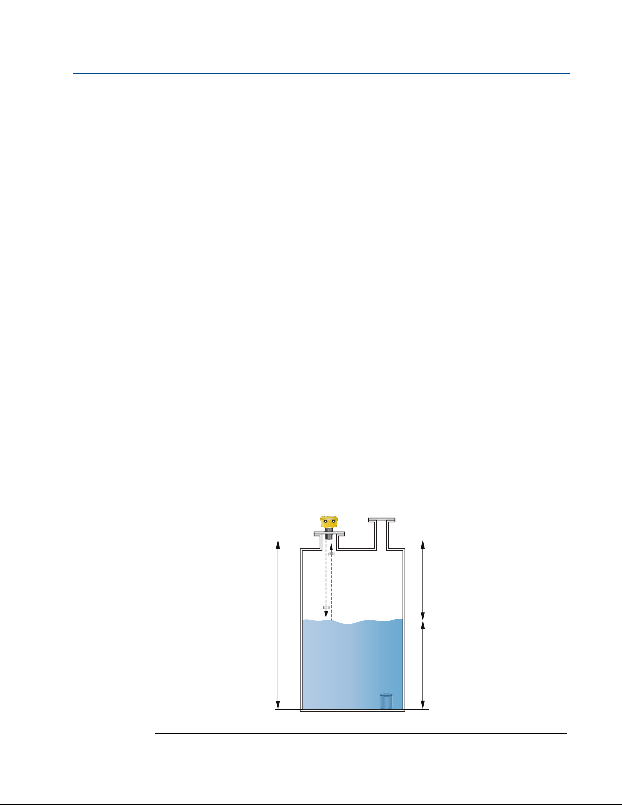
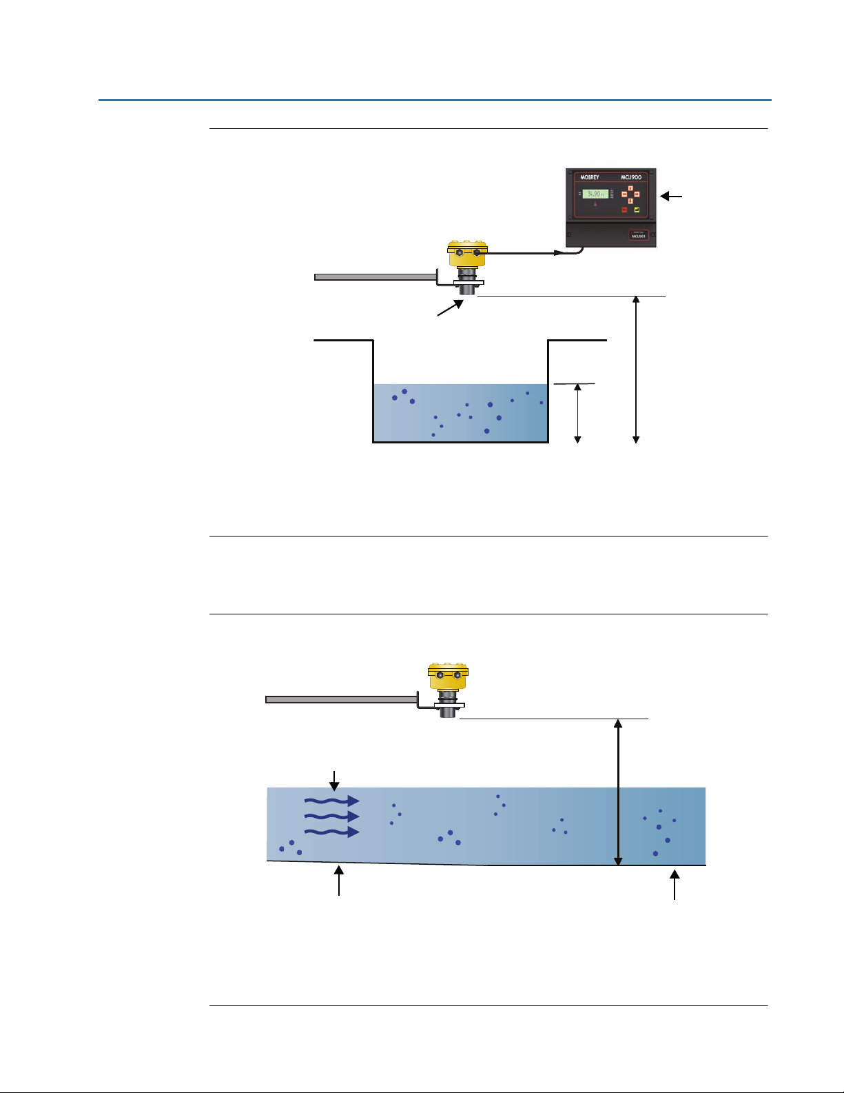
2.2 Theory of operation
The Mobrey MSP400RH and MSP900GH ultrasonic liquid level transmitters are mounted above
a liquid and use ultrasonic pulses to continuously measure the distance to the liquid surface. The
electronics calculate the distance to the liquid level using the time delay between transmitting
and receiving signals (Figure 2-1).
When programmed with the bottom reference of the application – usually the bottom of a tank
– the transmitter calculates the liquid depth (level), and outputs the result as a 4–20 mA signal
and a digital HART
®
signal.
The MSP400RH and MSP900GH can also calculate contents volume or open channel flow, when
programmed with further application information, and then outputs the result as a
4–20 mA signal and a digital HART signal.
Figure 2-1. Typical Application using Mobrey MSP400RH and MSP900GH transmitters
A. Transmitter Bottom Reference B. Distance C. Level
A
B
C
4
Reference Manual
IP2048/RM, Rev AA
Section 2: Transmitter Overview
February 2015
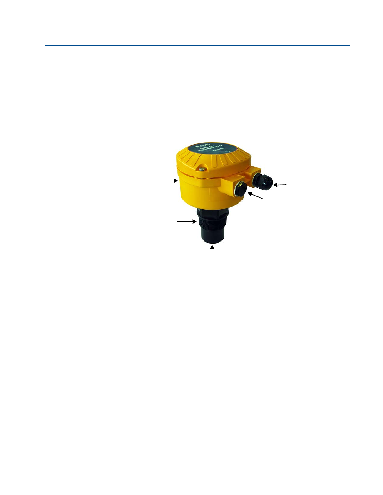
2.3 Components of the transmitter
The transmitter has a housing containing advanced electronics to generate ultrasonic pulses,
process the resultant signals, and provide a 4–20mA and HART output.
Removing the lid reveals terminals to connect a cable (not supplied) for the signal output and
an external power supply. An LCD inside the enclosure displays the selected measurement.
Programming is achieved using integral buttons or by remote communication using HART.
Figure 2-2. Features of the MSP400RH and MSP900GH transmitters
A. Electronics Housing C. Transmitter Face
B. 2-in. Mounting Thread D. M20 Conduit Threads
2.4 System architecture
The Mobrey MSP400RH and MSP900GH are two-wire, 24 Vdc loop-powered transmitters and
can be connected to a direct current (dc) power source using two-core, shielded cable.
The output can be a 4–20 mA analog signal and a digital HART signal.
Note
It is possible to use the multi-drop function with the HART protocol. In this case,
communication is restricted to digital since the current is fixed to 4 mA.
Each transmitter can be configured locally using the membrane-buttons which are revealed
after removing the housing cover. The transmitters can be configured remotely by using a
Mobrey MCU900 Series control unit
A comprehensive specification for the Mobrey MSP400RH and MSP900GH is in the section
“Specifications” on page 63.
D
C
B
A
Supplied with:
1 x Cable Gland
1 x Blanking Plug
D
5
Reference Manual
IP2048/RM, Rev AA
Section 2: Transmitter Overview
February 2015
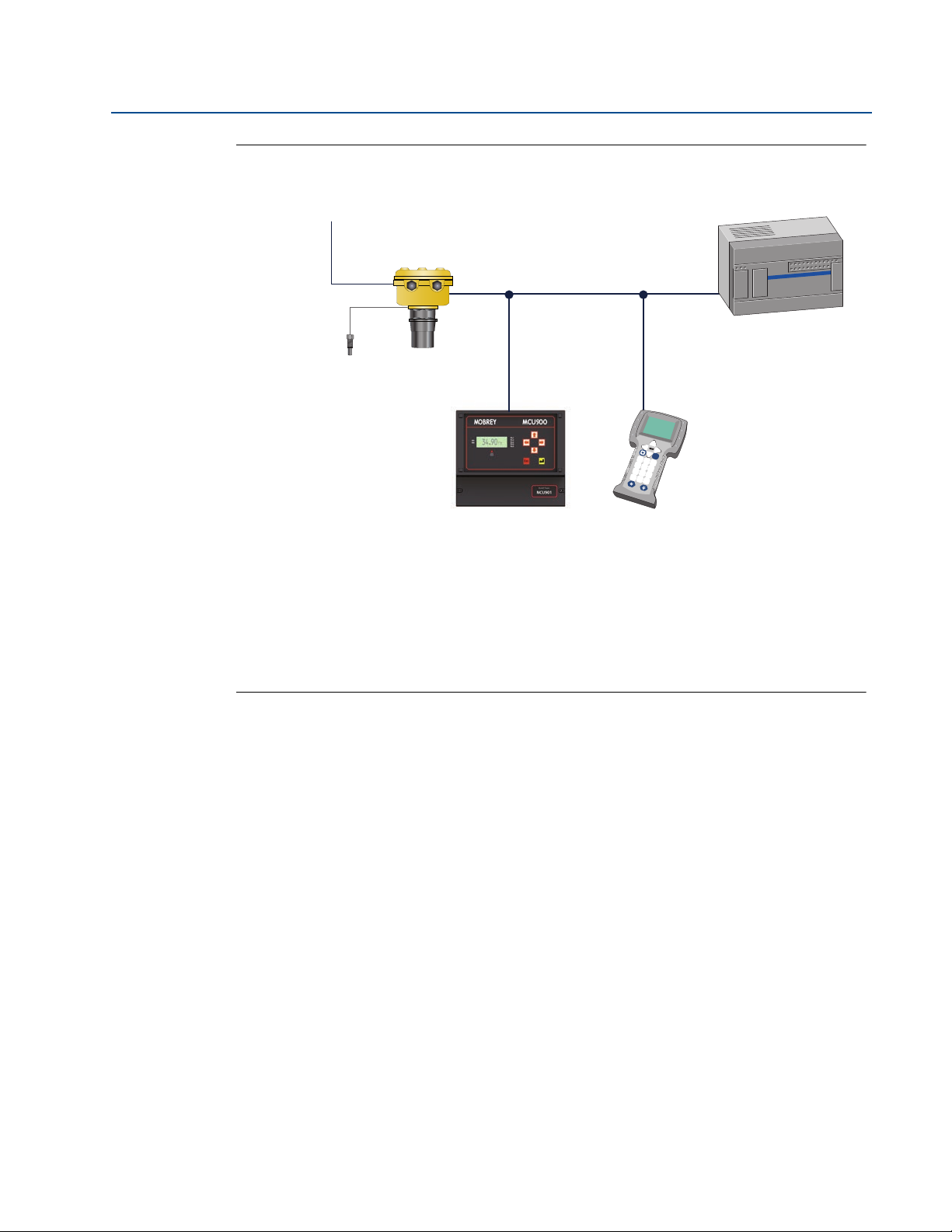
Figure 2-3. System architecture
A. Mobrey MSP Series Transmitter
B. Two Relay Outputs (MSP400RH only)
C. Mobrey Remote Temperature Sensor (Optional Accessory)
D. 4–20 mA / HART Signals
E. Mobrey MCU900 Series Control Unit
F. Field Communicator
G. Control System
Fn
1
2
3
4
5
6
7
8
9
0
-
.
B
G
C
A
D
E
F

6
Reference Manual
IP2048/RM, Rev AA
Section 2: Transmitter Overview
February 2015

Reference Manual
IP2048/RM, Rev AA
Section 3: Installation
February 2015
7
Section 3 Installation
Safety messages . . . . . . . . . . . . . . . . . . . . . . . . . . . . . . . . . . . . . . . . . . . . . . . . . . . . . . . . . page 7
Considerations before installation . . . . . . . . . . . . . . . . . . . . . . . . . . . . . . . . . . . . . . . . . page 8
Mechanical installation . . . . . . . . . . . . . . . . . . . . . . . . . . . . . . . . . . . . . . . . . . . . . . . . . . . page 9
Electrical installation . . . . . . . . . . . . . . . . . . . . . . . . . . . . . . . . . . . . . . . . . . . . . . . . . . . . . page 16
3.1 Safety messages
Procedures and instructions in this manual may require special precautions to ensure the safety
of the personnel performing the operations. Information that raises potential safety issues is
indicated by a caution symbol ( ). The external hot surface symbol ( ) is used when a surface
is hot and care must be taken to avoid possible burns. If there is a risk of an electrical shock the
( ) symbol is used. Refer to the safety messages listed at the beginning of each section before
performing an operation preceded by this symbol.
Failure to follow these installation guidelines could result in death or serious injury
Make sure only qualified personnel perform the installation.
Use the equipment only as specified in this manual. Failure to do so may impair the
protection provided by the equipment.
Explosions could result in death or serious injury
Verify that the operating environment of the transmitter is consistent with the
appropriate hazardous locations certifications.
Before connecting a HART
®
-based communicator in an explosive atmosphere, make
sure the instruments in the loop are installed in accordance with intrinsically safe or
non-incendive field wiring practices.
Electrical shock could cause death or serious injury
Use extreme caution when making contact with the leads and terminals.
Any substitution of non-recognized parts may jeopardize safety. Repair, e.g. substitution of
components etc., may also jeopardize safety and is under no circumstances allowed.

8
Reference Manual
IP2048/RM, Rev AA
Section 3: Installation
February 2015
3.2 Considerations before installation
The Mobrey MSP400RH and MSP900GH transmitters can be used for level and contents volume
measurements in open or closed tanks, or for open channel flow measurements.
The transmitter must be installed in a location where it is protected from ultraviolet radiation to
prevent long term degradation of the plastics used e.g. shrouded from direct sunlight.
It is important to correctly position the transmitter for reliable ultrasonic level measurement.
For maximum accuracy and stability of the level measurement reading, the transmitter should
always be shrouded from direct sunlight and radiated heat.
The transmitter may be site-tuned to deal with most application conditions, but it is
recommended that the following guidelines be adopted where relevant.
3.2.1 Safety considerations
Guidelines
1. Installation must be carried out by suitably trained personnel in accordance with the
applicable code of practice.
2. If the equipment is likely to come into contact with aggressive substances, it is the
responsibility of the user to take suitable precautions that prevent it from being
adversely affected, thus ensuring that the type of protection is not compromised.
Aggressive substances are acidic liquids or gases that may attack metals or solvents
that may affect polymeric materials.
Suitable precautions are regular checks as part of routine inspections, or establishing,
from the material's datasheet, that it is resistant to specific chemicals.
3. The equipment must only be cleaned with a damp cloth.
4. The equipment is not intended to be repaired by the user and is to be replaced by an
equivalent certified unit. Repairs should only be carried out by the manufacturer or
approved repairer.
5. The transmitter is double insulated, and therefore Protective Earthing is not required.
However, the cable shield/screen should be connected to a suitable ground (earth) at
one end only (see “Connecting the cable(s) to the transmitter” on page 16).
6. Note that if the equipment is used in a manner not specified by the manufacturer, the
protection afforded by the equipment may be impaired.
7. To ensure electro-magnetic compatibility in any European member state, it should not
be installed in a residential area.
Note
It is not advisable to mount the transmitter in close proximity to a source of electrical
noise such as a variable-speed drive, or other high-powered electrical device.

9
Reference Manual
IP2048/RM, Rev AA
Section 3: Installation
February 2015
3.3 Mechanical installation
Guidelines
1. Mount the transmitter above the liquid surface using the 2-inch thread provided, but
not closer than 12 in. (0,3 m) to the surface. The transmitter does not detect any liquid
surface closer than 12 in. (0,3 m) to the transmitter face. (See “Mounting the
transmitter above the liquid surface” on page 11).
Optional flanges and bracket kits are available to help mounting. (See Rosemount
Measurement product data sheet IP2045 for accessory part numbers.)
2. The transmitter should be mounted vertically to ensure a good echo from the liquid
surface. The transmitter beam half angle of the is 6 degrees. (See Figure 3-1 on
page 10).
3. Obstructions in the tank, or well, may generate echoes which can be confused with the
real liquid surface echo. Obstructions within the beam angle generate strong false
echoes. Wherever possible, the transmitter should be positioned to avoid false echoes.
4. To avoid detecting unwanted objects in the tank or well, it is advisable to maintain a
distance of at least 1.3 in. from the center line of the transmitter for every foot (11 cm
per meter) range to the obstruction.
5. No false echoes are generated if the transmitter is located near the side of the tank or
well, and the wall is smooth and free of protrusions. However, there will still be a
reduction in the echo size. It is recommended that the transmitter be mounted no
closer than 12 in. (0,3 m) to the wall to avoid a large reduction in the echo size.
6. If the transmitter is mounted in an enclosed tank with a domed top, avoid mounting
the transmitter in the center of the tank roof because this could act as a parabolic
reflector and create unwanted echoes.
7. Avoid applications where heavy condensation could form on the transmitter face.
8. If the transmitter is mounted in a stand-off or nozzle, the transmitter face should
protrude at least 0.2 in. (5 mm) into the tank. If this is not possible, see “Mounting the
transmitter above the liquid surface” on page 11).
9. If the transmitter is used in environments where direct sunlight can cause high surface
temperatures on exposed surfaces, a sun-shade is recommended.
10. Check that the maximum liquid level will not enter the 12-in. (0,3 m) blanking zone of
the transmitter.
10
Reference Manual
IP2048/RM, Rev AA
Section 3: Installation
February 2015
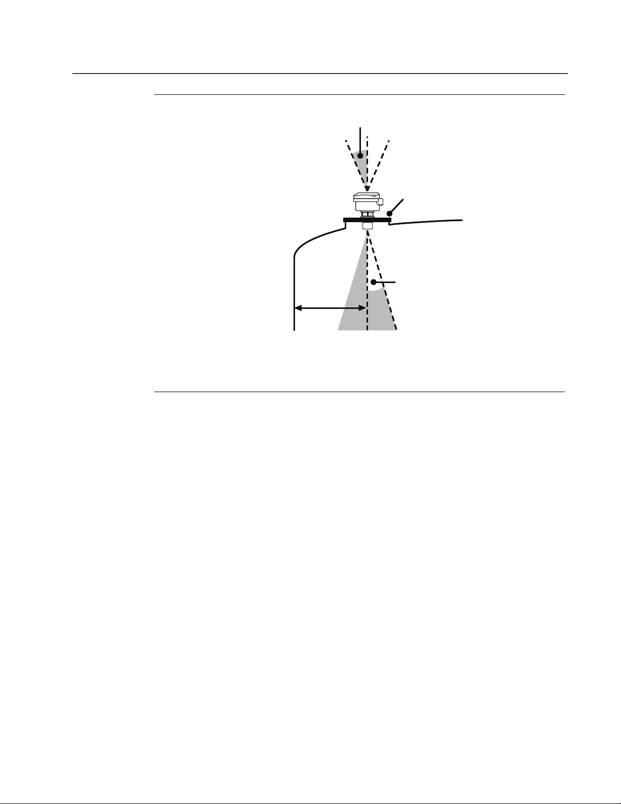
Figure 3-1. Min And Max Distances From Tank Wall
A. Transmitter is mounted vertically (maximum deviation of 3°).
B. Use a non-metallic fitting or flange.
C. 6° beam half angle
D. 1.3 in./ft. (11 cm/m). Minimum of 12 in. (0.3 m).
3.3.1 Consider the liquid surface conditions
Guidelines
1. Foaming liquids can reduce the size of the returned echo because foam is a poor
ultrasonic reflector.
Mount an ultrasonic transmitter over an area of clear liquid, such as near the inlet to a
tank or well. In extreme conditions, or where this is not possible, the transmitter may
be mounted in a vented stilling tube provided that the inside measurement of the
stilling tube is at least 4 in. (100 mm) and is smooth and free from joints or protrusions.
It is important that the bottom of the stilling tube stays covered to prevent the ingress
of foams.
2. Avoid mounting the transmitter directly over any inlet stream.
3.3.2 In-tank effects
Guidelines
1. Stirrers or agitators can cause a vortex. Mount the transmitter off-center of any vortex
to maximize the return echo.
2. If stirrer blades become uncovered, they create echoes as they pass through the
ultrasonic beam. The transmitter can learn to ignore these false echoes (see page 56 or
page 93 for further information).
A
D
B
C

11
Reference Manual
IP2048/RM, Rev AA
Section 3: Installation
February 2015
3. In tanks with rounded or conical bottoms, mount the transmitter off-center. If needed,
a perforated reflector plate can be installed on the tank bottom directly under the
transmitter center line to ensure a satisfactory return echo.
4. Avoid detecting pump casings, as the liquid falls away, by not mounting the transmitter
directly above pumps. If this is not possible, fine-tuning of the transmitter on-site may
be required.
3.3.3 Mounting the transmitter above the liquid surface
A 2-in. thread is provided to mount the transmitter. The thread form is either BSPT or NPT, and is
clearly marked on the hexagon of the transmitter body.
Note
The Mobrey MSP400RH and MSP900GH are designed to be mounted in a non-metallic
fitting or flange. The use of metallic fittings/flanges is not recommended.
To help installation, flange accessories and bracket kits are available from Emerson Process
Management (see Product Data Sheet IP2045 for accessory part numbers). The accessory
flanges supplied are manufactured from PVC and are a full face design. Care must be taken
when installing to raised face mating flanges on the tank or vessel to prevent distortion of the
PVC flange by over-tightening the bolts.
Bracket mounting
The bracket kit contains a stainless steel angle bracket and PVC threaded disc, which may be
used to mount the transmitter on a support over the liquid surface. See Product Data Sheet
IP2045 for accessory part numbers.
The bracket and disc dimensions are in Figure A-4 on page 69. The combined weight of bracket
and disc is 16 oz (0,5 kg). For transmitter weight, see “Specifications” on page 63.
Bracket installation procedure
1. Attach bracket to the disc using the three screws provided.
2. Attach the assembled bracket and disc to a rigid support over the liquid surface. The
bracket may be bolted to a suitable crossmember (structural section of steel).
3. Use PTFE tape on the screw thread (Figure 3-3 on page 13).
4. Insert the transmitter into the disc.
5. Tighten to a torque of 1.5 lbf.ft. (2 Nm) using the hexagon. Do not use the transmitter
housing to tighten.
12
Reference Manual
IP2048/RM, Rev AA
Section 3: Installation
February 2015
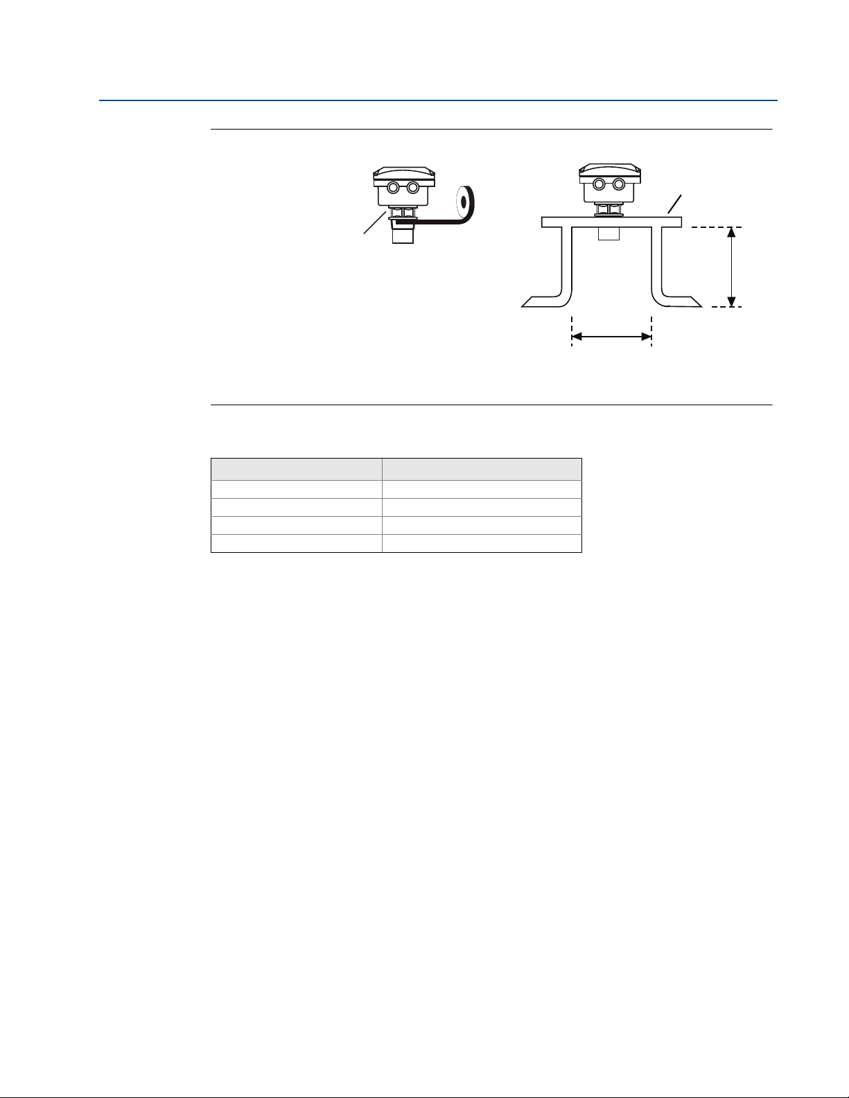
Figure 3-2. Mounting the transmitter using a bracket kit
A. Stainless steel bracket
B. No. 4X 13 long self tap screw (3 positions), carbon steel (zinc plated)
C. PVC disc
Installing in a tank with a nozzle or stand-off
Installation procedure
1. Use PTFE tape on the screw thread of the transmitter (Figure 3-3).
2. If the tank has a flanged nozzle or stand-off:
a. Attach the transmitter to a non-metal instrument flange using the threaded
connection. Tighten to a torque of 1.5 lb-ft (2 N-m) using the transmitter’s hexagon.
b. The instrument (accessory) flanges supplied by Emerson Process Management are
manufactured from PVC and are a full face design. Care must be taken when installing
to a raised face mating flange on the tank or vessel to prevent distortion of the PVC
flange by over-tightening the bolts.
c. Ensure the gasket is sitting correctly on the tank flange.
d. Lower the assembled transmitter and instrument flange onto the tank flange, and
secure with appropriate bolting to a suitable torque for the flanges.
If mating to a raised face flange (RF) on the tank nozzle or stand-off, tighten to a
maximum torque of 10 lb-ft (13.6 N-m).
3. If the tank has a threaded nozzle or stand-off:
a. Attach the transmitter to the nozzle/stand-off using the threaded connection.
b. Tighten to a torque of 1.5 lb-ft (2 N-m) using the transmitter’s hexagon.
Note
If the transmitter face does not protrude into the vessel, note the dimensions in
Table 3-1 on page 3-13 for Figure 3-3, and ensure that the nozzle/vessel weld is smooth
and free from internal weld beads or other projections.
B
C
A
Note: Combined weight of bracket
and disc is 16 oz (0,5 kg).
13
Reference Manual
IP2048/RM, Rev AA
Section 3: Installation
February 2015
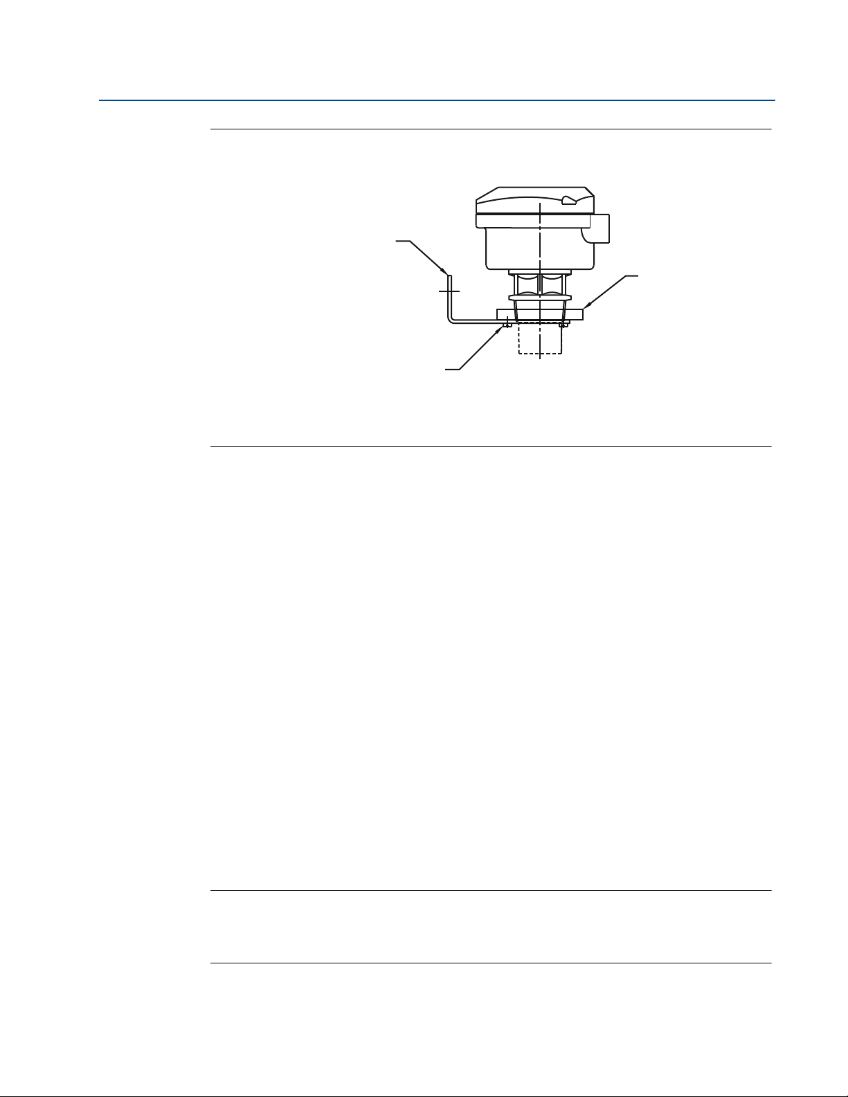
Figure 3-3. Mounting the transmitter using a nozzle/stand-off
D. See dimension D in Table 3-1.
L. See dimension L in Table 3-1.
Table 3-1. Nozzle diameter size and maximum length
3.3.4 Open channel flow installations
There are normally two distinct parts to an open channel flow measurement system; the
primary element (flow structure) and the secondary element (Head measurement instrumenta-
tion). For accurate open channel flow measurement, both parts of the system must be correctly
installed.
This section explains the important parts of installing the transmitter (secondary element). The
flow structure (primary element) installation can be referenced in the British (BS3680) or ISO
International standards.
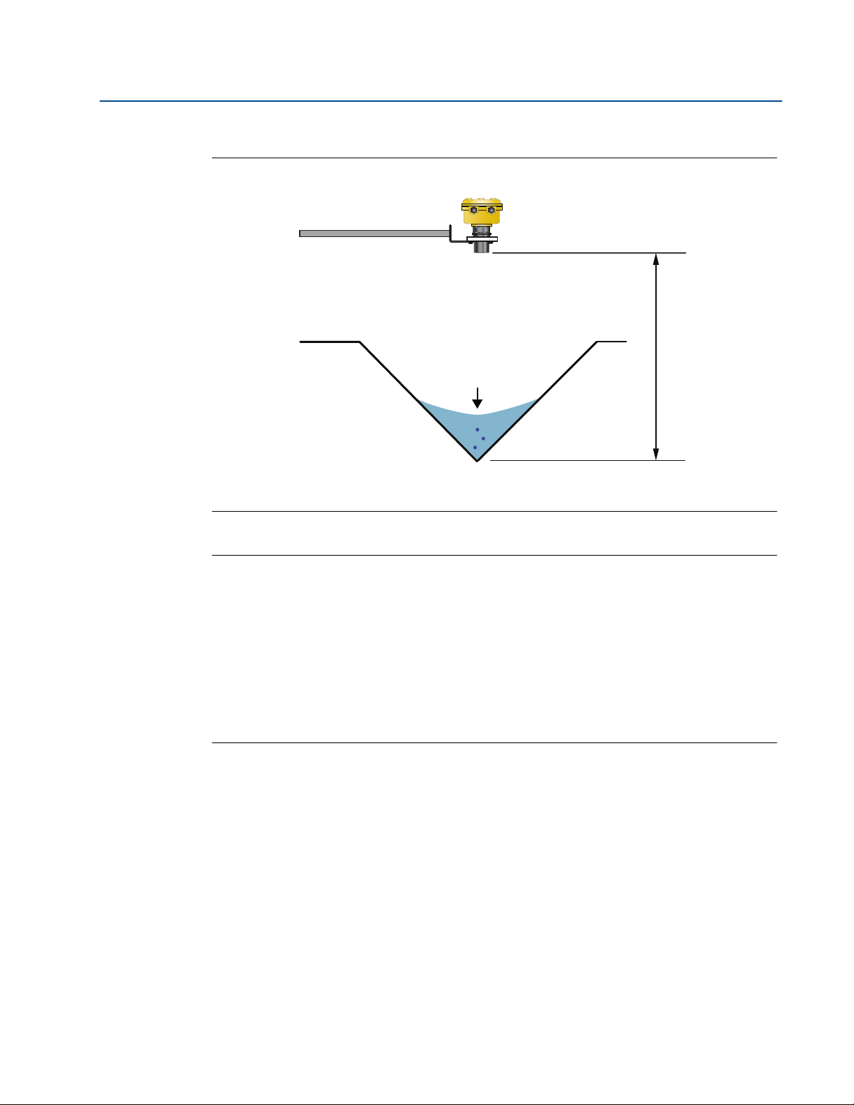
Positioning of the transmitter is critical, and should be the correct distance upstream from the
flow structure as stated in the relevant standard for your country. For example, in the ISO
standards, the distance should be four to five times the maximum height of the water (H
max
) for
a thin plate weir, or three to four times H
max
for a flume. For optimum accuracy, the
transmitter’s front face should be positioned at a height equal to the maximum flow depth plus
14 in. (0,35 m).
Nozzle Diameter Size (D) Maximum Nozzle Length (L)
DN50 (2 in.) 4 in. (100 mm)
DN80 (3 in.) 6.3 in. (160 mm)
DN100 (4 in.) 6.3 in. (160 mm)
DN125 (5 in.) 11.8 in. (300 mm)
PTFE
L
D
Tighten To A Torque Of 1.5 lbf.ft.
(2 Nm) Using The Hexagon. Do
Not Use The Housing To Tighten
Use Non-metallic
Fitting / Flange
14
Reference Manual
IP2048/RM, Rev AA
Section 3: Installation
February 2015
Figure 3-4. Choosing the height position above a flow
A. Transmitter front face
B. Hmax
C. Hmax + 14 in.
D. Mobrey MCU900 Series control unit
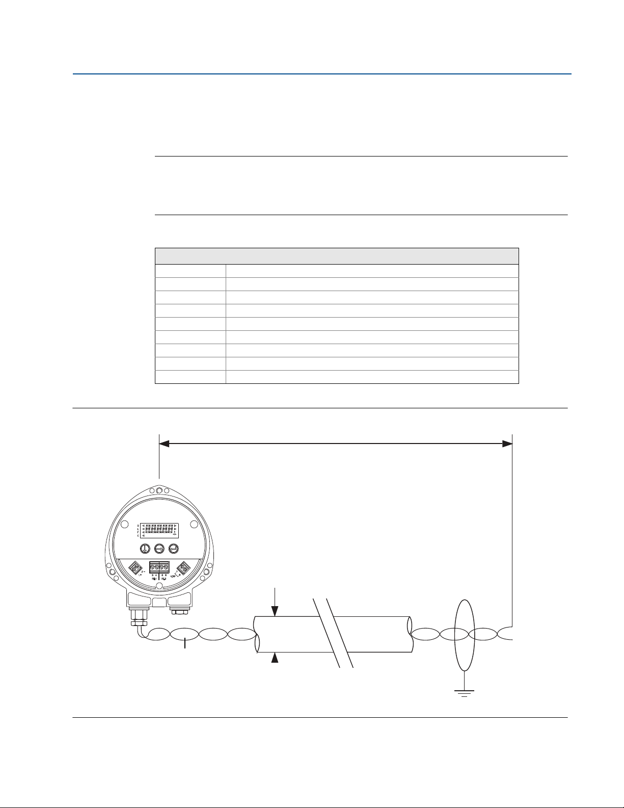
It is important that the bottom reference of the transmitter should be related to the datum of
the primary measuring device (see Figure 3-6).
Figure 3-5. Transmitter bottom reference for a flume or weir
A. Transmitter bottom reference
B. Primary element (e.g. flume, weir) invert
C. Approach channel
D. Flow direction
A
B
C
D
C
D
B
A
15
Reference Manual
IP2048/RM, Rev AA
Section 3: Installation
February 2015
Figure 3-6. Transmitter bottom reference for a ‘V’ notch weir
A. Transmitter bottom reference (i.e. true invert)
B. Meniscus Level
Note
The transmitter should be free from a situation where it is likely to 'drown' (refer to
relevant Standard for further information).
The MSP400RH and MSP900GH have the option of a Remote Temperature Sensor for
temperature compensation (see “Remote temperature sensor” on page 19).
The temperature sensor should be mounted in a location where it can get an accurate
air temperature measurement and is protected from sunlight.
If the flow structure permits, mount the transmitter within the flow channel or
chamber. Shroud the transmitter from direct sunlight for maximum accuracy and
stability.
B
A

16
Reference Manual
IP2048/RM, Rev AA
Section 3: Installation
February 2015
3.4 Electrical installation
3.4.1 Connecting the cable(s) to the transmitter
The Mobrey MSP400RH and MSP900GH are two-wire loop-powered transmitters accepting
power supplies as follows:
MSP400RH:12 to 40 Vdc (non-hazardous area only)
MSP900GH:12 to 40 Vdc (non-hazardous area) or 12 to 30 Vdc (hazardous area)
Note
To comply with the CSA approval, a transmitter must be powered from a Mobrey
MCU900 Series control unit, or a class 2 or separate extra-low voltage (SELV) source.
Other devices may reset if connecting the transmitter to a multi-drop system while the
loop is powered. De-energize the loop to avoid devices being reset
Each transmitter is supplied with two cable entries. A suitable conduit system or cable gland
must be used to maintain the weather-proof rating and hazardous area protection. Any unused
entry must be sealed with a suitably rated blanking plug.
A two-core, shielded/screened cable is required for external power supply and output signal
connections. The cable is not supplied.
Connect the cable(s) to the transmitter
1. Make sure that the power supply is disconnected.
2. Undo the three cover screws and then lift the transmitter housing cover.
3. Pass the cable through the cable gland/conduit.
4. Connect the cable wires:
a. For the MSP400RH, see “Connecting the cable wires to the MSP400RH” on page 17.
b. For the MSP900GH, see “Connecting the cable wires to the MSP900GH” on page 18.
5. Connect the cable shield/screen to a suitable ground (earth) at one end only.
6. Replace the cover, tighten the cable gland, and connect the power supply.
What to do after completing the cabling
To maintain the weather-proof rating and hazardous area protection of the transmitter, ensure
all cable glands, blanking plugs, and seals are in good condition.
Check that the cover seal is in good condition, and not twisted or misaligned in the seal location
groove. When replacing the cover, tighten the three cover screws evenly to exert uniform
pressure on the cover seal.
17
Reference Manual
IP2048/RM, Rev AA
Section 3: Installation
February 2015
3.4.2 Connecting the cable wires to the MSP400RH
Connect the cable wires to the transmitter as shown in Figure 3-7. See also “Wiring to allow
HART communications” on page 19 if HART digital communications is required.
Note
Make sure the power supply is off when connecting the transmitter.
The MSP400RH is not intrinsically safe, and is for use in non-hazardous (ordinary
location) installations only.
Table 3-2. Terminal connections on the MSP400RH
Figure 3-7. Wiring Diagram for The MSP400RH
Connections
Terminal 1 24 Vdc
Terminal 2 0 Vdc
Terminal 3 RL1 (SPST) - see “Relays” on page 18
Terminal 4 RL1 (SPST) - see “Relays” on page 18
Terminal 5 RL2 (SPST) - see “Relays” on page 18
Terminal 6 RL2 (SPST) - see “Relays” on page 18
Terminal 7 Remote temperature sensor (if used) - see page 19
Terminal 8 Remote temperature sensor (if used) - see page 19
Earth Screen Connect the cable shield/screen to ground (earth) in the control room
Min. 12 Vdc
Ø4 to 8 mm
(0.15 to 0.31 in.)
Twisted-pair, Screened
Min. 0.22mm
2
(24 SWG / 23 AWG)
Max. 1.5mm
2
(16 SWG / 18 AWG)
0 Vdc
Max. 3000 m (9750 ft.)
+12 to 30 Vdc

18
Reference Manual
IP2048/RM, Rev AA
Section 3: Installation
February 2015
Relays
The MSP400RH has two integral relays which may be used for fault indication or control
purposes. These relays are for light duty and should be used as signal relays only, with control
functions being performed by external control relays.
Relay 2 is defaulted as a 'fault' relay - normally energized - but may be re-configured
on-site as a set-point relay if required.
Relay status indicators are on the LCD inside the housing (see “Display and
push-buttons” on page 21.)
3.4.3 Connecting the cable wires to the MSP900GH
The MSP900GH is for intrinsically safe installations.
Note
Make sure the power supply is off when connecting the transmitter.
Installation in a non-hazardous (ordinary location) area
Connect the cable wires to the transmitter as shown in Figure 3-8 on page 19. See also “Wiring
to allow HART communications” on page 19 if HART digital communications is required.
Installation in a hazardous area
Connect the cable wires to the transmitter as shown in Figure 3-8 on page 19. See also “Wiring
to allow HART communications” on page 19 if HART digital communications is required.
When the MSP900GH is powered by a Mobrey MCU900 Series control unit, no safety barriers are
required as the output from the control unit is Intrinsically Safe.
If powering the transmitter from any other power supply, ensure a suitable intrinsically safe
barrier is fitted in the non-hazardous (safe) area. The barrier must be chosen such that its output
parameters Uo, Io and Po are less than Ui, Ii and Pi of the transmitter (see Appendix B: Product
Certifications). The sum of the capacitance and the inductance of the transmitter and the
connecting cable fitted must not exceed the maximum specified for the barrier chosen.
Note
Make sure that the instruments in the loop are installed according to intrinsically-safe
field wiring practices and control drawings, when applicable.
Table 3-3. Connections for The MSP900GH
Connections
Terminal 1 24 Vdc
Terminal 2 0 Vdc
Terminal 7
(1)
(1) See “Remote temperature sensor” on page 19 for further information.
Remote temperature sensor (if used).
Terminal 8
(1)
Remote temperature sensor (if used).
Earth Screen Connect the cable shield/screen to ground (earth) in the control room.
19
Reference Manual
IP2048/RM, Rev AA
Section 3: Installation
February 2015
Figure 3-8. Wiring diagram for the MSP900GH
3.4.4 Remote temperature sensor
The MSP400RH and MSP900GH accept input from a Mobrey Remote Temperature Sensor
(see Product Data Sheet IP2045 for accessory part numbers).
This is a thermistor-based temperature sensor designed for use with the MSP400RH and
MSP900GH.
Full installation instructions are supplied with the temperature sensor, but it should be mounted
out of direct sunlight in a position so that it can give a representative reading of the air
temperature between the liquid surface and the transmitter.
Note
Do not connect any other temperature sensor to the MSP400RH or the MSP900GH.
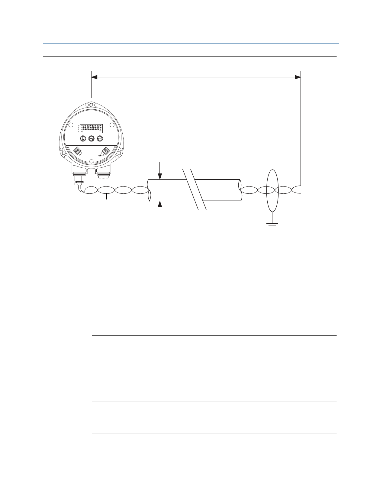
3.4.5 Wiring to allow HART communications
If HART communications is required, a 250 Ohms (minimum), 0.25 W load resistor must be
installed in the loop. (See “Dimension drawings” on page 68).
Note
When the transmitter is used with a Mobrey MCU900 Series control unit, there is no
need to install an external load resistor in the loop because a suitable resistor is built in
to the control unit.
Min. 12 Vdc
Ø4 to 8 mm
(0.15 to 0.31 in.)
Twisted-pair, Screened
Min. 0.22 mm
2
(24 SWG / 23 AWG)
Max. 1.5 mm
2
(16 SWG / 18 AWG)
0 Vdc
Max. 3000 m (9750 ft.)
+12 to 40 Vdc
(Non I.S. Application)
or
+12 to 30 Vdc From
Protective Barrier
(I.S. application.)

20
Reference Manual
IP2048/RM, Rev AA
Section 3: Installation
February 2015
If the transmitter is being supplied through a safety barrier, ensure the type chosen will pass
HART information.
After the load resistor is installed, a Field Communicator can be connected across the load
resistor. It is the responsibility of the installer to ensure that any Field Communicator used in the
hazardous area is suitably certified.
Note
Make sure that the instruments in the loop are installed according to intrinsically-safe
field wiring practices and control drawings, when applicable.
3.4.6 Lightning / Surge protection and other loop devices
If the area is prone to lightning strikes or voltage surges, a suppressor device may be installed
between the transmitter and the control unit.
If an additional loop-powered device or separately powered device is included in the two-wire
loop, ensure the transmitter receives a minimum voltage of
12 Vdc. (See “Dimension drawings” on page 68).
Loading...