


 Loading...
Installation Manual
20001700, Rev CC
April 2013
Micro Motion® Model 1700 and 2700
Installation Manual
Safety messages
Safety messages are provided throughout this manual to protect personnel and equipment. Read each safety message carefully before proceeding to the next step.
Micro Motion customer service
•Worldwide: flow.support@emerson.com
•Asia-Pacific: APflow.support@emerson.com
North and South America |
Europe and Middle East |
Asia Pacific |
|
|
|||
|
|
|
|
|
|
|
|
United States |
800-522-6277 |
U.K. |
0870 240 1978 |
Australia |
800 |
158 727 |
|
|
|
|
|
|
|
|
|
Canada |
+1 303-527-5200 |
The Netherlands |
+31 (0) 318 495 555 |
New Zealand |
099 |
128 804 |
|
|
|
|
|
|
|
|
|
Mexico |
+41 |
(0) 41 7686 111 |
France |
0800 917 901 |
India |
800 |
440 1468 |
|
|
|
|
|
|
|
|
Argentina |
+54 |
11 4837 7000 |
Germany |
0800 182 5347 |
Pakistan |
888 |
550 2682 |
|
|
|
|
|
|
|
|
Brazil |
+55 |
15 3238 3677 |
Italy |
8008 77334 |
China |
+86 |
21 2892 9000 |
|
|
|
|
|
|
|
|
Venezuela |
+58 |
26 1731 3446 |
Central & Eastern |
+41 (0) 41 7686 111 |
Japan |
+81 |
3 5769 6803 |
|
|
|
|
|
|
|
|
|
|
|
Russia/CIS |
+7 495 981 9811 |
South Korea |
+82 |
2 3438 4600 |
|
|
|
|
|
|
|
|
|
|
|
Egypt |
0800 000 0015 |
Singapore |
+65 |
6 777 8211 |
|
|
|
|
|
|
|
|
|
|
|
Oman |
800 70101 |
Thailand |
001 |
800 441 6426 |
|
|
|
|
|
|
|
|
|
|
|
Qatar |
431 0044 |
Malaysia |
800 |
814 008 |
|
|
|
|
|
|
|
|
|
|
|
Kuwait |
663 299 01 |
|
|
|
|
|
|
|
|
|
|
|
|
|
|
South Africa |
800 991 390 |
|
|
|
|
|
|
|
|
|
|
|
|
|
|
Saudia Arabia |
800 844 9564 |
|
|
|
|
|
|
|
|
|
|
|
|
|
|
UAE |
800 0444 0684 |
|
|
|
|
|
|
|
|
|
|
|

Contents
Contents
Chapter 1 |
Planning ......................................................................................................................... |
1 |
|
|
1.1 |
Flowmeter components ................................................................................................................ |
1 |
|
1.2 |
Outputs option identification ....................................................................................................... |
5 |
|
1.3 |
Environmental limits ..................................................................................................................... |
7 |
|
1.4 |
Hazardous area classifications ....................................................................................................... |
7 |
|
1.5 |
Power requirements ..................................................................................................................... |
7 |
|
1.6 |
Orientation ................................................................................................................................... |
8 |
|
1.7 |
Accessibility for maintenance ....................................................................................................... |
9 |
Chapter 2 |
Mounting and sensor wiring for integral installations ................................................... |
11 |
|
|
2.1 |
Mounting and sensor wiring ....................................................................................................... |
11 |
|
2.2 |
Rotate the transmitter on the sensor (optional) .......................................................................... |
11 |
|
2.3 |
Rotate the user interface on the transmitter (optional) ............................................................... |
12 |
|
2.4 |
Ground the flowmeter components ........................................................................................... |
14 |
Chapter 3 |
Mounting and sensor wiring for 4-wire remote installations ......................................... |
15 |
|
|
3.1 |
Mounting options ....................................................................................................................... |
15 |
|
3.2 |
Prepare the 4-wire cable ............................................................................................................. |
19 |
|
3.3 |
Wire the transmitter to the sensor .............................................................................................. |
22 |
|
3.4 |
Rotate the user interface on the transmitter (optional) ............................................................... |
24 |
|
3.5 |
Ground the flowmeter components ........................................................................................... |
26 |
Chapter 4 |
Mounting and sensor wiring for 9-wire remote installations ......................................... |
29 |
|
|
4.1 |
Mounting options ....................................................................................................................... |
29 |
|
4.2 |
Prepare the 9-wire cable ............................................................................................................. |
31 |
|
4.3 |
Wire the transmitter to the sensor using jacketed cable .............................................................. |
37 |
|
4.4 |
Wire the transmitter to the sensor using shielded or armored cable ........................................... |
40 |
|
4.5 |
Rotate the user interface on the transmitter (optional) ............................................................... |
45 |
|
4.6 |
Ground the flowmeter components ........................................................................................... |
47 |
Chapter 5 |
Mounting and sensor wiring for remote core processor with remote sensor |
|
|
|
installations .................................................................................................................. |
49 |
|
|
5.1 |
Mounting options ....................................................................................................................... |
49 |
|
5.2 |
Mount the remote core processor ............................................................................................... |
53 |
|
5.3 |
Prepare the 4-wire cable ............................................................................................................. |
54 |
|
5.4 |
Wire the transmitter to the remote core processor ..................................................................... |
57 |
|
5.5 |
Prepare the 9-wire cable ............................................................................................................. |
59 |
|
5.6 |
Wire the remote core processor to the sensor using jacketed cable ............................................ |
65 |
|
5.7 |
Wire the remote core processor to the sensor using shielded or armored cable .......................... |
69 |
|
5.8 |
Rotate the user interface on the transmitter (optional) ............................................................... |
74 |
|
5.9 |
Ground the flowmeter components ........................................................................................... |
75 |
Chapter 6 |
Wiring the power supply ............................................................................................... |
77 |
|
|
6.1 |
Wire the power supply ................................................................................................................ |
77 |
Chapter 7 |
I/O wiring for Model 1700 and Model 2700 transmitters with analog outputs ................ |
79 |
|
|
7.1 |
Basic analog wiring ..................................................................................................................... |
79 |
|
7.2 |
HART/analog single loop wiring .................................................................................................. |
80 |
|
7.3 |
RS-485 point-to-point wiring ...................................................................................................... |
81 |
|
7.4 |
HART multidrop wiring ............................................................................................................... |
81 |
Installation Manual |
i |

Contents
Chapter 8 |
I/O wiring for Model 1700 and Model 2700 transmitters with intrinsically safe |
|
|
|
outputs ......................................................................................................................... |
83 |
|
|
8.1 |
Safe area mA output wiring ......................................................................................................... |
83 |
|
8.2 |
Safe area HART/analog single-loop wiring ................................................................................... |
84 |
|
8.3 |
Safe area HART multidrop wiring ................................................................................................ |
85 |
|
8.4 |
Safe area frequency output/discrete output wiring ..................................................................... |
86 |
|
8.5 |
Hazardous area wiring ................................................................................................................ |
87 |
Chapter 9 |
I/O wiring for Model 2700 transmitters with configurable input/outputs |
......................95 |
|
|
9.1 |
Channel configuration ................................................................................................................ |
95 |
|
9.2 |
mA/HART wiring ......................................................................................................................... |
96 |
|
9.3 |
Frequency output wiring ............................................................................................................. |
98 |
|
9.4 |
Discrete output wiring .............................................................................................................. |
103 |
|
9.5 |
Discrete input wiring ................................................................................................................ |
107 |
Chapter 10 Specifications .............................................................................................................. |
109 |
|
10.1 |
Electrical connections ............................................................................................................... |
109 |
10.2 |
Input/output signals ................................................................................................................. |
110 |
10.3 |
Local display ............................................................................................................................. |
111 |
10.4 |
Environmental limits ................................................................................................................. |
113 |
10.5 |
Physical specifications .............................................................................................................. |
113 |
Index ................................................................................................................................................ |
|
117 |
ii |
Micro Motion® Model 1700 and 2700 |

Planning
1 Planning
Topics covered in this chapter:
•Flowmeter components
•Outputs option identification
•Environmental limits
•Hazardous area classifications
•Power requirements
•Orientation
•Accessibility for maintenance
1.1Flowmeter components
The transmitter is one component of a Micro Motion flowmeter. The other major component is the sensor.
A third component, called the core processor, provides additional memory and processing functions.
1.1.1Installation types
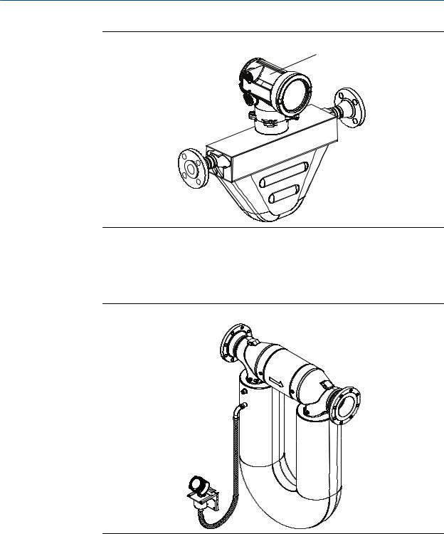
Model 1700 and Model 2700 transmitters can be installed five different ways, only one of which applies to your specific installation.
•Integral – The transmitter is mounted directly on the sensor. You do not need to install the transmitter separately, but you will need to connect power supply and I/O wiring.
Installation Manual |
1 |
Planning
Figure 1-1: Integral installation
Transmitter
 Sensor
•High-temperature flexible conduit – Some high-temperature meters come preinstalled with a flexible conduit between the sensor and the transmitter. You do not have to connect any wires between the transmitter and the sensor, but you do need to mount the electronics separately and connect power and I/O wiring to the transmitter.
Figure 1-2: High-temperature flexible conduit installation
High-temperature flexible conduit installations use the same installation instructions as 4-wire remote installations, except that the distance between the sensor and the electronics is limited by the length of the flexible conduit.
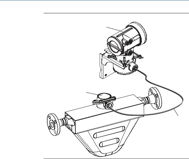
•4-wire remote – The transmitter is installed remotely from the sensor. You need to mount the transmitter separately from the sensor, connect a 4-wire cable between the transmitter and sensor, and connect power and I/O wiring to the transmitter.
2 |
Micro Motion® Model 1700 and 2700 |

Planning
Figure 1-3: 4-wire remote installation – painted aluminum housing
Transmitter
Core processor
4-wire cable


 Sensor
Figure 1-4: 4-wire remote installation – stainless steel housing
Transmitter
Core processor
4-wire cable


 Sensor
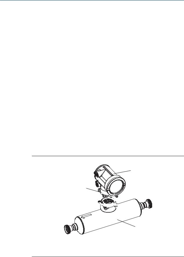
•9-wire remote – The transmitter and core processor are combined in a single unit that is installed remotely from the sensor. You need to mount the transmitter/core processor assembly separately from the sensor, connect a 9-wire cable between the transmitter/core processor, and connect power and I/O wiring to the transmitter.
Installation Manual |
3 |
Planning
Figure 1-5: 9-wire remote installation type
Transmitter
Junction box
9-wire cable
 Sensor
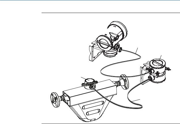
•Remote core processor with remote sensor – A remote core process with remote sensor installation separates all three components – transmitter, core processor, and sensor – all of which are installed separately. A 4-wire cable connects the transmitter to the core processor, and a 9-wire cable connects the core processor to the sensor.
4 |
Micro Motion® Model 1700 and 2700 |
Planning
Figure 1-6: Remote core processor with remote sensor installation type
Transmitter

4-wire cable
Core processor
Junction box
9-wire cable

 Sensor
1.1.2Maximum cable lengths
The maximum cable length between flowmeter components that are separately installed is determined by cable type. See Table 1-1.
Table 1-1: Maximum cable lengths
Cable type |
Wire gauge |
Maximum length |
Micro Motion 4-wire |
Not applicable |
1000 ft (300 m) |
|
|
|
Micro Motion 9-wire |
Not applicable |
60 ft (20 m) |
|
|
|
User-supplied 4-wire |
VDC 22 AWG (0.35 mm2) |
300 ft (90 m) |
|
VDC 20 AWG (0.5 mm2) |
500 ft (150 m) |
|
VDC 18 AWG (0.8 mm2) |
1000 ft (300 m) |
|
RS-485 22 AWG (0.35 mm2) or |
1000 ft (300 m) |
|
larger |
|
|
|
|
1.2Outputs option identification
You must know your transmitter's output option to correctly install the transmitter.
Installation Manual |
5 |

Planning
The transmitter's model number is on a tag on the side of the transmitter. You can use the model number to determine the transmitter's output option. The first four characters are the transmitter type. The fifth character is the installation type. The eighth character is the output option. The remaining characters are not relevant to transmitter installation.
Figure 1-7: Model code identification
Transmitter type
Output option
Installation type
Table 1-2: Installation types for Model 1700 and Model 2700 transmitters
Letter |
Description |
R |
Remote mount 4-wire |
|
|
I |
Integral |
|
|
C |
Remote mount 9-wire (painted aluminum housing) |
|
|
B |
Remote core processor with remote transmitter |
|
|
M |
Remote mount 4-wire (stainless steel housing) |
|
|
P |
Remote mount 9-wire (stainless steel housing) |
|
|
Table 1-3: Output options for Model 1700 and Model 2700 transmitters
Letter |
Description |
A |
Analog outputs – one mA, one frequency, one RS-485 |
|
|
B |
Configurable I/O channels (default configuration of two mA, one frequency) |
|
|
C |
Configurable I/O channels (custom configuration ) |
|
|
D |
Intrinsically safe analog outputs – two mA, one frequency/discrete |
|
|
E |
Intrinsically safe Foundation fieldbus H1 with standard function blocks |
|
|
G |
PROFIBUS-PA |
|
|
N |
Non-incendive Foundation fieldbus H1 with standard function blcoks |
|
|
2 |
WirelessHART – one mA, one frequency, one RS-485 |
|
|
3 |
WirelessHART – one mA, two configurable I/O channels (custom configura- |
|
tion) |
|
|
4 |
Intrinsically safe WirelessHART – two mA, one frequency |
|
|
6 |
Micro Motion® Model 1700 and 2700 |
Planning
Table 1-4: Output options for Model 1500 and Model 2500 transmitters
Letter |
Description |
A |
Analog outputs – one mA, one frequency, one RS-485 |
|
|
B |
Configurable I/O channels (default configuration of two mA, one frequency) |
|
|
C |
Configurable I/O channels (custom configuration ) |
|
|
1.3Environmental limits
Table 1-5: Environmental specifications
Type |
Value |
Ambient temperature limits |
–40 to +140 °F (–40 to +60 °C) |
|
|
Humidity limits |
5 to 95% relative humidity, non-condensing at 140 °F (60 °C) |
|
|
Vibration limits |
Meets IEC68.2.6, endurance sweep, 5 to 2000 Hz, 50 sweep cy- |
|
cles at 1.0 g |
|
|
EMI effects |
Complies with EMC Directive 2004/108/EC per EN 61326 Indus- |
|
trial |
|
Complies with NAMUR NE-21 (22.08.2007) |
|
|
Ambient temperature effect on |
On mA output: ±0.005% of span per °C |
analog outputs |
|
|
|
If possible, install the transmitter in a location that will prevent direct exposure to sunlight. The environmental limits for the transmitter may be further restricted by hazardous area approvals.
1.4Hazardous area classifications
If you plan to mount the transmitter in a hazardous area:
•Verify that the transmitter has the appropriate hazardous area approval. Each transmitter has a hazardous area approval tag attached to the transmitter housing.
•Ensure that any cable used between the transmitter and the sensor meets the hazardous area requirements.
1.5Power requirements
Self-switching AC/DC input, automatically recognizes supply voltage
•85 to 265 VAC, 50/60 Hz, 6 watts typical, 11 watts maximum
Installation Manual |
7 |

Planning
•18 to 100 VDC, 6 watts typical, 11 watts maximum
•Complies with low voltage directive 2006/95/EC per EN 61010-1 (IEC 61010-1) with amendment 2, and Installation (Overvoltage) Category II, Pollution Degree 2
Note
For DC power:
•Power requirements assume a single transmitter per cable.
•At startup, the power source must provide a minimum of 1.5 amps of short-term current per transmitter.
•Length and conductor diameter of the power cable must be sized to provide 18 VDC minimum at the power terminals, at a load current of 0.5 amps.
Figure 1-8: Cable sizing formula
M = 18V + (R × L × 0.5A)
•M: minimum supply voltage
•R: cable resistance
•L: cable length
Table 1-6: Typical power cable resistance at 68 °F (20 °C)
Wire gauge |
Resistance |
|
14 AWG |
0.0050 |
Ω/ft |
|
|
|
16 AWG |
0.0080 |
Ω/ft |
|
|
|
18 AWG |
0.0128 |
Ω/ft |
|
|
|
20 AWG |
0.0204 |
Ω/ft |
|
|
|
2.5 mm2 |
0.0136 |
Ω/m |
1.5 mm2 |
0.0228 |
Ω/m |
1.0 mm2 |
0.0340 |
Ω/m |
0.75 mm2 |
0.0460 |
Ω/m |
0.50 mm2 |
0.0680 |
Ω/m |
1.6Orientation
You can mount the transmitter in any orientation as long as the conduit openings do not point upward.
 CAUTION!
Upward-facing conduit openings risk condensation moisture entering the transmitter housing, which could damage the transmitter.
8 |
Micro Motion® Model 1700 and 2700 |

Planning
1.7Accessibility for maintenance
Mount the flowmeter in a location and orientation that satisfies the following conditions:
•Allows sufficient clearance to open the transmitter housing cover. Micro Motion recommends 8–10 inches (200–250 mm) clearance at the rear of the transmitter.
•Provides clear access for installing cabling to the transmitter.
Installation Manual |
9 |

Planning
10 |
Micro Motion® Model 1700 and 2700 |
Mounting and sensor wiring for integral installations
2 Mounting and sensor wiring for integral installations
Topics covered in this chapter:
•Mounting and sensor wiring
•Rotate the transmitter on the sensor (optional)
•Rotate the user interface on the transmitter (optional)
•Ground the flowmeter components
2.1Mounting and sensor wiring
There are no separate mounting requirements for integral transmitters, and no need to connect wiring between the transmitter and the sensor.
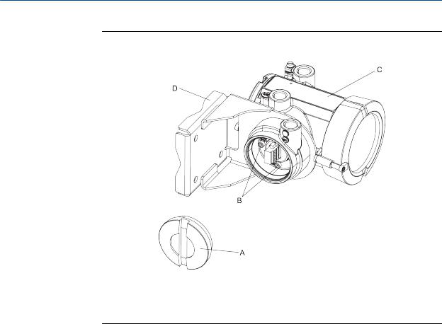
2.2Rotate the transmitter on the sensor (optional)
In integral installations, you can rotate the transmitter on the sensor up to 360º in 90º increments.
Figure 2-1: Components of an integral transmitter
B
C
A


D
A.Cap screws
B.Transmitter
C.Transition ring
D.Sensor
Installation Manual |
11 |

Mounting and sensor wiring for integral installations
1.Loosen each of the four cap screws (4 mm) that fasten the transmitter to the base.
2.Rotate the transmitter counter-clockwise so that the cap screws are in the unlocked position.
3.Gently lift the transmitter straight up, disengaging it from the cap screws.
Important
Do not disconnect or damage the wires that connect the transmitter to the core processor.
4.Rotate the transmitter to the desired orientation.
Important
Do not pinch or stress the wires.
The slots on the transition ring should be aligned with the cap screws.
5.Gently lower the transmitter onto the base, inserting the cap screws into the slots.
6.Rotate the transmitter clockwise so that the cap screws are in the locked position.
7.Tighten the cap screws, torquing to 20 to 30 in-lbs (2.3 to 3.4 N-m).
2.3Rotate the user interface on the transmitter (optional)
The user interface on the transmitter electronics module can be rotated 90º or 180° from the original position.
12 |
Micro Motion® Model 1700 and 2700 |

Mounting and sensor wiring for integral installations
Figure 2-2: Display components
A.Transmitter housing
B.Sub-bezel
C.Display module
D.Display screws
E.End-cap clamp
F.Cap screw
G.Display cover
1.Shut off power to the unit.
2.Remove the end-cap clamp by removing the cap screw.
3.Turn the display cover counterclockwise to remove it from the main enclosure.
4.Carefully loosen (and remove if necessary) the semicaptive display screws while holding the display module in place.
5.Carefully pull the display module out of the main enclosure until the sub-bezel pin terminals are disengaged from the display module.
Note
If the display pins come out of the board stack with the display module, remove the pins and reinstall them.
6.Rotate the display module to the desired position.
7.Insert the sub-bezel pin terminals into the display module pin holes to secure the display in its new position.
8.If you have removed the display screws, line them up with the matching holes on the sub-bezel, then reinsert and tighten them.
9.Place the display cover onto the main enclosure.
Installation Manual |
13 |
Mounting and sensor wiring for integral installations
10.Turn the display cover clockwise until it is snug.
11.Replace the end-cap clamp by reinserting and tightening the cap screw.
12.Restore power to the transmitter.
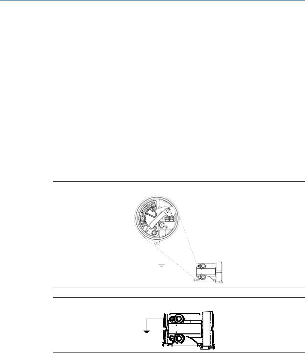
2.4Ground the flowmeter components
In an integral installation, all components are grounded together.
If national standards are not in effect, adhere to the following guidelines for grounding:
•Use copper wire, 14 AWG (2.5 mm2) or larger wire size.
•Keep all ground leads as short as possible, less than 1 Ω impedance.
•Connect ground leads directly to earth, or follow plant standards.
Ground via the piping, if possible (see sensor documentation). If grounding via the piping is not possible, ground according to applicable local standards using the transmitter’s internal or external ground screw.
Figure 2-3: Transmitter internal grounding screw
Figure 2-4: Transmitter external grounding screw
14 |
Micro Motion® Model 1700 and 2700 |

Mounting and sensor wiring for 4-wire remote installations
3 Mounting and sensor wiring for 4- wire remote installations
Topics covered in this chapter:
•Mounting options
•Prepare the 4-wire cable
•Wire the transmitter to the sensor
•Rotate the user interface on the transmitter (optional)
•Ground the flowmeter components
3.1Mounting options
There are two options available for mounting the transmitter:
•Mount the transmitter to a wall or flat surface.
•Mount the transmitter to an instrument pole.
3.1.1Mount the transmitter to a wall
•Use four 5/16-inch diameter (or M8) bolts and nuts that can withstand the process environment. Micro Motion does not supply bolts or nuts (appropriate bolts and nuts are available as an option).
•Ensure that the surface is flat and rigid, does not vibrate, or move excessively.
1.If desired, re-orient the transmitter on the mounting bracket.
a.Remove the junction end-cap from the junction housing.
b.Loosen each of the four cap screws (4 mm).
c.Rotate the bracket so that the transmitter is oriented as desired.
d.Tighten the cap screws, torquing to 30 to 38 in-lbs (3 to 4 N-m).
e.Replace the junction end-cap.
Installation Manual |
15 |

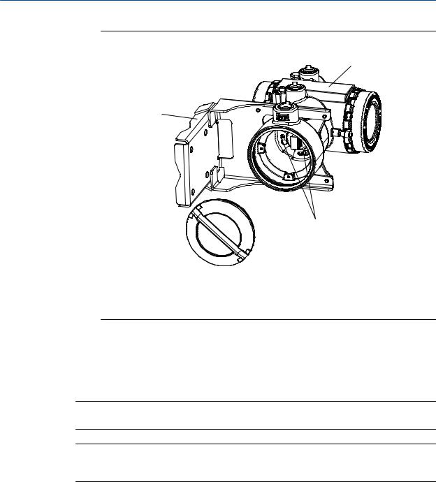
Mounting and sensor wiring for 4-wire remote installations
Figure 3-1: Components of 4-wire remote mount transmitter (aluminum housing)
A.End cap
B.Cap screws
C.Transmitter
D.Mounting bracket
16 |
Micro Motion® Model 1700 and 2700 |
Mounting and sensor wiring for 4-wire remote installations
Figure 3-2: Components of a 4-wire remote mount transmitter (stainless steel housing)
C
D
B
 A
A
A.End cap
B.Cap screws
C.Transmitter
D. Mounting bracket
2. Attach the mounting bracket to the wall.
3.1.2Mount the transmitter to an instrument pole
•Use two 5/16-inch U-bolts for 2-inch pipe, and four matching nuts, that can withstand the process environment. Micro Motion does not supply U-bolts or nuts (appropriate bolts and nuts are available as an option).
•Ensure the instrument pole extends at least 12 inches (305 mm) from a rigid base, and is no more than 2 inches (50.8 mm) in diameter.
1.If desired, re-orient the transmitter on the mounting bracket.
a.Remove the junction end-cap from the junction housing.
b.Loosen each of the four cap screws (4 mm).
c.Rotate the bracket so that the transmitter is oriented as desired.
d.Tighten the cap screws, torquing to 30 to 38 in-lbs (3 to 4 N-m).
e.Replace the junction end-cap.
Installation Manual |
17 |
Mounting and sensor wiring for 4-wire remote installations
Figure 3-3: Components of 4-wire remote mount transmitter (aluminum housing)
A.End cap
B.Cap screws
C.Transmitter
D.Mounting bracket
18 |
Micro Motion® Model 1700 and 2700 |
Mounting and sensor wiring for 4-wire remote installations
Figure 3-4: Components of a 4-wire remote mount transmitter (stainless steel housing)
C
D
B
 A
A
A.End cap
B.Cap screws
C.Transmitter
D.Mounting bracket
2.Attach the mounting bracket to an instrument pole.
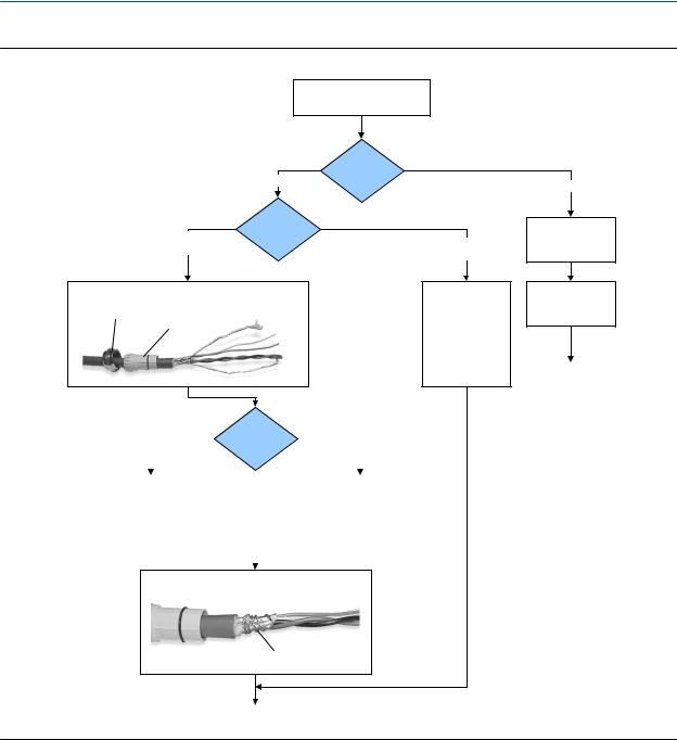
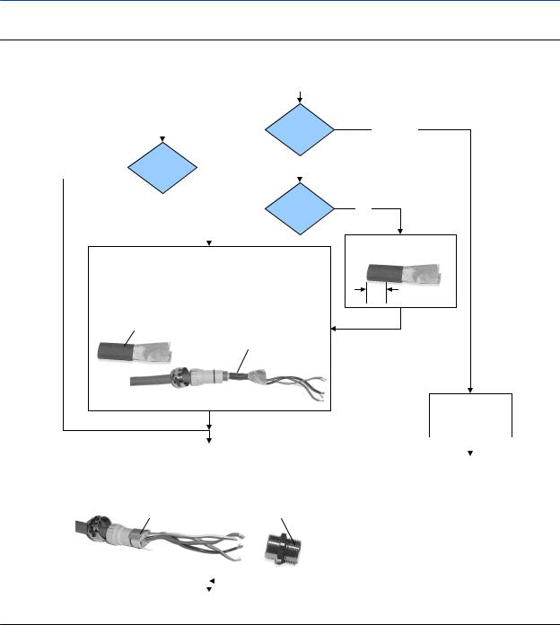
3.2Prepare the 4-wire cable
Important
For user-supplied cable glands, the gland must be capable of terminating the drain wires.
Note
If you are installing unshielded cable in continuous metallic conduit with 360º termination shielding, you only need to prepare the cable – you do not need to perform the shielding procedure.
Installation Manual |
19 |
Mounting and sensor wiring for 4-wire remote installations
Figure 3-5: 4-wire cable preparation
Remove the core processor cover
Cable glands
Gland supplier
Micro Motion cable gland
Pass the wires through the gland nut and clamping insert.
Gland nut |
Clamping |
|
|
|
insert |
Cable layout
User-supplied
cable gland
Pass the wires through the gland. Terminate the drain wires inside the gland.
|
|
|
NPT |
|
Gland type |
|
|
M20 |
|
|
|||
|
|
|
|
|
|
||||||||
|
|
|
|
|
|
|
|
|
|
|
|
|
|
|
|
|
|
|
|
|
|
|
|
|
|
|
|
1. |
Strip 4-1/2 inch (115 mm) of cable jacket. |
|
|
1. |
Strip 4-1/4 inch (108 mm) of cable jacket. |
||||||||
2. |
Remove the clear wrap and filler material. |
|
|
2. |
Remove the clear wrap and filler material. |
||||||||
3. |
Strip all but 3/4 inch (19 mm) of shielding. |
|
|
3. |
Strip all but 1/2 inch (12 mm) of shielding. |
||||||||
|
|
|
|
|
|
|
|
|
|
|
|
|
|
|
|
|
|
|
|
|
|
|
|
|
|
|
|
|
|
|
|
|
|
|
|
|
|
|
|
|
|
Wrap the drain wires twice around the shield and cut off the excess drain wires.
Drain wires wrapped around shield
Metal conduit
Run conduit to sensor
Lay cable in conduit
Done
(do not perform the shielding procedure)
Go to the shielding procedure
20 |
Micro Motion® Model 1700 and 2700 |
Mounting and sensor wiring for 4-wire remote installations
Figure 3-6: 4-wire cable shielding
From the preparation procedure
|
|
|
|
|
Micro Motion |
|
|
Gland supplier |
|||||
|
|
|
|
|
|
cable gland |
|
|
|
||||
|
|
Cable shield |
|
|
|
|
|
|
|
|
|
||
|
|
|
|
|
|
|
|
|
|
|
|||
|
|
|
|
|
Foil |
|
|
||||||
Braided |
|
|
|||||||||||
(armored cable) |
|
type |
|
|
(shielded cable) |
|
|
|
|||||
|
|
|
|
|
|
|
|
|
|
|
|
Gland type |
|
|
|
|
|
|
|
|
|
|
|
||||
|
|
|
|
|
|
|
|
NPT |
|
|
|||
|
|
|
|
|
|
|
|
|
|
|
|
|
|
Apply the Heat Shrink
1.Slide the shielded heat shrink over the drain wires. Ensure that the wires are completely covered.
2.Apply heat (250 °F or 120 °C) to shrink the tubing. Do not burn the cable.
3.Position the clamping insert so the interior end is flush with the braid of the heat shrink.
Shielded heat shrink
After heat applied
User-supplied
cable gland
M20
Trim 7 mm from the shielded heat shrink
Trim
Terminate the shield and drain wires in the gland
|
|
|
|
|
|
|
Assemble the Gland |
|
|
|
|
||
|
|
|
|
|||
1. |
Fold the shield or braid back over the clamping insert and 1/8 inch |
|
|
|
||
|
Assemble the gland |
|||||
|
(3 mm) past the O-ring. |
|
|
|||
2. |
Install the gland body into the conduit opening on the core processor housing. |
|
according to vendor |
|||
3. |
Insert the wires through gland body and tighten the gland nut onto the gland body. |
|
instructions |
|||
|
Shield folded back |
Gland body |
|
|
|
|
|
|
|
|
|||
|
|
|
|
|
|
|
|
|
|
|
|
|
|
|
|
|
|
|
|
|
Done
3.2.14-wire cable types and usage
Micro Motion offers two types of 4-wire cable: shielded and armored. Both types contain shield drain wires.
The 4-wire cable supplied by Micro Motion consists of one pair of red and black 18 AWG (0.75 mm2) wires for the VDC connection, and one pair of white and green 22 AWG (0.35 mm2) wires for the RS-485 connection.
User-supplied 4-wire cable must meet the following requirements:
Installation Manual |
21 |

Mounting and sensor wiring for 4-wire remote installations
• Twisted pair construction.
• Applicable hazardous area requirements, if the core processor is installed in a hazardous area.
• Wire gauge appropriate for the cable length between the core processor and the transmitter.
Table 3-1: Wire gauge
Wire gauge |
Maximum cable length |
VDC 22 AWG (0.35 mm2) |
300 ft (90 m) |
VDC 20 AWG (0.5 mm2) |
500 ft (150 m) |
VDC 18 AWG (0.8 mm2) |
1000 ft (300 m) |
RS-485 22 AWG (0.35 mm2) or larger |
1000 ft (300 m) |
3.3 Wire the transmitter to the sensor
1.Connect the cable to the core processor as described in the sensor documentation.
2.Feed the wires from the sensor through the conduit opening.
3.Connect wires to the appropriate terminals on the mating connector.
Important
Never ground the shield, braid, or drain wire(s) at the transmitter.
Tip
You may find it easier to unplug the mating connector to connect the wires. If you do so, remember to firmly reseat the mating connector and tighten the mating connector screws so that the mating connector cannot accidentally come loose.
22 |
Micro Motion® Model 1700 and 2700 |
Mounting and sensor wiring for 4-wire remote installations
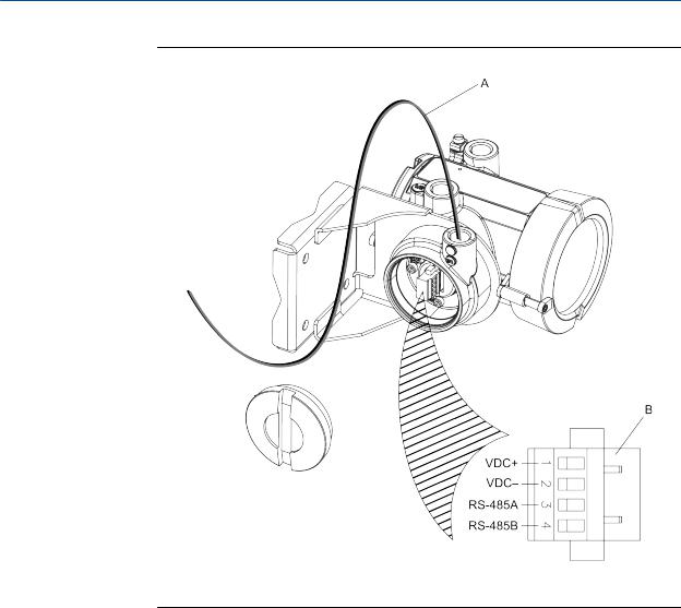
Figure 3-7: Wiring path for transmitters with aluminum housing
A.4-wire cable
B.Mating connector
Installation Manual |
23 |
Mounting and sensor wiring for 4-wire remote installations
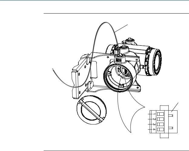
Figure 3-8: Wiring path for transmitters with stainless steel housing
A
B
VDC+
VDC–
RS-485A
RS-485B
A.4-wire cable
B.Mating connector
3.4Rotate the user interface on the transmitter (optional)
The user interface on the transmitter electronics module can be rotated 90º or 180° from the original position.
24 |
Micro Motion® Model 1700 and 2700 |
Mounting and sensor wiring for 4-wire remote installations
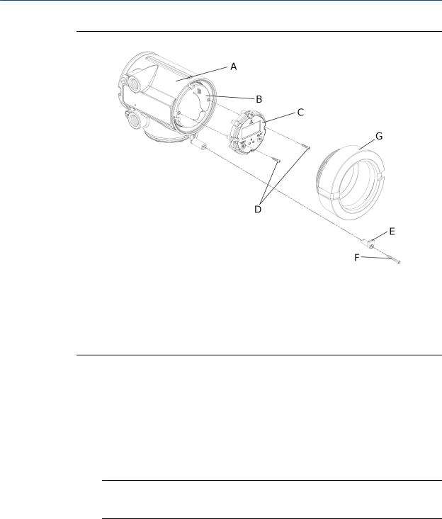
Figure 3-9: Display components
A.Transmitter housing
B.Sub-bezel
C.Display module
D.Display screws
E.End-cap clamp
F.Cap screw
G.Display cover
1.Shut off power to the unit.
2.Remove the end-cap clamp by removing the cap screw.
3.Turn the display cover counterclockwise to remove it from the main enclosure.
4.Carefully loosen (and remove if necessary) the semicaptive display screws while holding the display module in place.
5.Carefully pull the display module out of the main enclosure until the sub-bezel pin terminals are disengaged from the display module.
Note
If the display pins come out of the board stack with the display module, remove the pins and reinstall them.
6.Rotate the display module to the desired position.
7.Insert the sub-bezel pin terminals into the display module pin holes to secure the display in its new position.
8.If you have removed the display screws, line them up with the matching holes on the sub-bezel, then reinsert and tighten them.
9.Place the display cover onto the main enclosure.
Installation Manual |
25 |

Mounting and sensor wiring for 4-wire remote installations
10.Turn the display cover clockwise until it is snug.
11.Replace the end-cap clamp by reinserting and tightening the cap screw.
12.Restore power to the transmitter.
3.5Ground the flowmeter components
In 4-wire remote installations, the transmitter and sensor are grounded separately.
 CAUTION!
Improper grounding could cause inaccurate measurements or flow meter failure. Failure to comply with requirements for intrinsic safety in a hazardous area could result in an explosion.
Note
For hazardous area installations in Europe, refer to standard EN 60079-14 or national standards.
If national standards are not in effect, adhere to the following guidelines for grounding:
•Use copper wire, 14 AWG (2.5 mm2) or larger wire size.
•Keep all ground leads as short as possible, less than 1 Ω impedance.
•Connect ground leads directly to earth, or follow plant standards.
1.Ground the sensor according to the instructions in the sensor documentation.
2.Ground the transmitter according to applicable local standards, using the transmitter’s internal or external ground screw.
Figure 3-10: Transmitter internal grounding screw
26 |
Micro Motion® Model 1700 and 2700 |
Loading...