


 Loading...
Installation Manual
P/N 20001700, Rev. C
November 2007
Micro Motion®
Model 1700 and
Model 2700 Transmitters
Installation Manual
©2007, Micro Motion, Inc. All rights reserved. ELITE and ProLink are registered trademarks, and MVD and MVD Direct Connect are trademarks of Micro Motion, Inc., Boulder, Colorado. Micro Motion is a registered trade name of Micro Motion, Inc., Boulder, Colorado. The Micro Motion and Emerson logos are trademarks and service marks of Emerson Electric Co. All other trademarks are property of their respective owners.
Contents
Chapter 1 Before You Begin . . . . . . . . . . . . . . . . . . . . . . . . . . . . . . . . . . . . . 1
1.1 Overview . . . . . . . . . . . . . . . . . . . . . . . . . . . . . . . . . . . . . . . . . . . . . . . . . . . . . . . . . . . 1 1.2 Safety . . . . . . . . . . . . . . . . . . . . . . . . . . . . . . . . . . . . . . . . . . . . . . . . . . . . . . . . . . . . . 1 1.3 Flowmeter components. . . . . . . . . . . . . . . . . . . . . . . . . . . . . . . . . . . . . . . . . . . . . . . . 2 1.4 Transmitter type, installation type, and outputs option board . . . . . . . . . . . . . . . . . . . 2 1.5 Transmitter installation procedures . . . . . . . . . . . . . . . . . . . . . . . . . . . . . . . . . . . . . . . 3 1.6 Flowmeter documentation. . . . . . . . . . . . . . . . . . . . . . . . . . . . . . . . . . . . . . . . . . . . . . 3 1.7 Micro Motion customer service . . . . . . . . . . . . . . . . . . . . . . . . . . . . . . . . . . . . . . . . . . 4
Chapter 2 Installing the Transmitter . . . . . . . . . . . . . . . . . . . . . . . . . . . . . . . |
5 |
2.1 Overview . . . . . . . . . . . . . . . . . . . . . . . . . . . . . . . . . . . . . . . . . . . . . . . . . . . . . . . . . . . 5 2.2 Installation architecture . . . . . . . . . . . . . . . . . . . . . . . . . . . . . . . . . . . . . . . . . . . . . . . . 5 2.3 Determining an appropriate location . . . . . . . . . . . . . . . . . . . . . . . . . . . . . . . . . . . . . . 7 2.3.1 Environmental requirements . . . . . . . . . . . . . . . . . . . . . . . . . . . . . . . . . . . 7 2.3.2 Hazardous area classifications . . . . . . . . . . . . . . . . . . . . . . . . . . . . . . . . . 7 2.3.3 Power source . . . . . . . . . . . . . . . . . . . . . . . . . . . . . . . . . . . . . . . . . . . . . . . 7 2.3.4 Maximum cable lengths . . . . . . . . . . . . . . . . . . . . . . . . . . . . . . . . . . . . . . . 9 2.3.5 Accessibility for maintenance. . . . . . . . . . . . . . . . . . . . . . . . . . . . . . . . . . . 9
2.4 Mounting the transmitter . . . . . . . . . . . . . . . . . . . . . . . . . . . . . . . . . . . . . . . . . . . . . . . 9 2.4.1 Integral installations . . . . . . . . . . . . . . . . . . . . . . . . . . . . . . . . . . . . . . . . . 10
2.4.24-wire remote or remote core processor with remote
transmitter installations . . . . . . . . . . . . . . . . . . . . . . . . . . . . . . . . . . . . . . 11 2.4.3 9-wire remote installations . . . . . . . . . . . . . . . . . . . . . . . . . . . . . . . . . . . . 12 2.5 Mounting the remote core processor . . . . . . . . . . . . . . . . . . . . . . . . . . . . . . . . . . . . 13
2.6 Grounding the flowmeter components . . . . . . . . . . . . . . . . . . . . . . . . . . . . . . . . . . . 15 2.7 Supplying power . . . . . . . . . . . . . . . . . . . . . . . . . . . . . . . . . . . . . . . . . . . . . . . . . . . . 16 2.8 Rotating the display. . . . . . . . . . . . . . . . . . . . . . . . . . . . . . . . . . . . . . . . . . . . . . . . . . 16
Chapter 3 Wiring the Transmitter to the Sensor . . . . . . . . . . . . . . . . . . . . . . . |
19 |
3.1 Overview . . . . . . . . . . . . . . . . . . . . . . . . . . . . . . . . . . . . . . . . . . . . . . . . . . . . . . . . . . 19 3.2 Cable types . . . . . . . . . . . . . . . . . . . . . . . . . . . . . . . . . . . . . . . . . . . . . . . . . . . . . . . . 19 3.2.1 4-wire cable . . . . . . . . . . . . . . . . . . . . . . . . . . . . . . . . . . . . . . . . . . . . . . . 20 3.2.2 9-wire cable . . . . . . . . . . . . . . . . . . . . . . . . . . . . . . . . . . . . . . . . . . . . . . . 20
3.3 Wiring for 4-wire remote installations . . . . . . . . . . . . . . . . . . . . . . . . . . . . . . . . . . . . 20 3.4 Wiring for 9-wire remote installations . . . . . . . . . . . . . . . . . . . . . . . . . . . . . . . . . . . . 22 3.5 Wiring for remote core processor with remote transmitter installations. . . . . . . . . . . 23
Chapter 4 Output Wiring – Model 1700/2700 Analog Transmitters . . . . . . . . . . |
29 |
4.1 Overview . . . . . . . . . . . . . . . . . . . . . . . . . . . . . . . . . . . . . . . . . . . . . . . . . . . . . . . . . . 29 4.2 Output terminals and output types . . . . . . . . . . . . . . . . . . . . . . . . . . . . . . . . . . . . . . 29 4.3 Output wiring . . . . . . . . . . . . . . . . . . . . . . . . . . . . . . . . . . . . . . . . . . . . . . . . . . . . . . . 29
Installation Manual |
iii |
Contents
Chapter 5 Output Wiring – Model 1700/2700 Intrinsically Safe Transmitters . . . |
33 |
5.1 Overview . . . . . . . . . . . . . . . . . . . . . . . . . . . . . . . . . . . . . . . . . . . . . . . . . . . . . . . . . . 33 5.2 Output terminals and output types . . . . . . . . . . . . . . . . . . . . . . . . . . . . . . . . . . . . . . 33 5.3 Safe area output wiring . . . . . . . . . . . . . . . . . . . . . . . . . . . . . . . . . . . . . . . . . . . . . . . 34 5.3.1 Safe area mA output wiring . . . . . . . . . . . . . . . . . . . . . . . . . . . . . . . . . . . 34 5.3.2 Safe area frequency/discrete output wiring . . . . . . . . . . . . . . . . . . . . . . . 36
5.4 Hazardous area output wiring . . . . . . . . . . . . . . . . . . . . . . . . . . . . . . . . . . . . . . . . . . 37 5.4.1 Hazardous area safety parameters . . . . . . . . . . . . . . . . . . . . . . . . . . . . . 37 5.4.2 Hazardous area mA output wiring . . . . . . . . . . . . . . . . . . . . . . . . . . . . . . 39 5.4.3 Hazardous area frequency/discrete output wiring . . . . . . . . . . . . . . . . . . 39
Chapter 6 Output Wiring – Model 2700 Configurable I/O Transmitters . . . . . . . 41
6.1 Overview . . . . . . . . . . . . . . . . . . . . . . . . . . . . . . . . . . . . . . . . . . . . . . . . . . . . . . . . . . 41 6.2 Channel configuration . . . . . . . . . . . . . . . . . . . . . . . . . . . . . . . . . . . . . . . . . . . . . . . . 41 6.3 mA output wiring . . . . . . . . . . . . . . . . . . . . . . . . . . . . . . . . . . . . . . . . . . . . . . . . . . . . 42 6.4 Frequency output wiring . . . . . . . . . . . . . . . . . . . . . . . . . . . . . . . . . . . . . . . . . . . . . . 44 6.5 Discrete output wiring . . . . . . . . . . . . . . . . . . . . . . . . . . . . . . . . . . . . . . . . . . . . . . . . 47 6.6 Discrete input wiring . . . . . . . . . . . . . . . . . . . . . . . . . . . . . . . . . . . . . . . . . . . . . . . . . 50
Chapter 7 Output Wiring – Model 2700 FOUNDATION fieldbus and PROFIBUS-PA Transmitters . . . . . . . . . . . . . . . . . . . . . . . . . . . . . . . . . . . . . . . 53
7.1 Overview . . . . . . . . . . . . . . . . . . . . . . . . . . . . . . . . . . . . . . . . . . . . . . . . . . . . . . . . . . 53 7.2 FOUNDATION fieldbus wiring. . . . . . . . . . . . . . . . . . . . . . . . . . . . . . . . . . . . . . . . . . . . 53 7.3 PROFIBUS-PA wiring . . . . . . . . . . . . . . . . . . . . . . . . . . . . . . . . . . . . . . . . . . . . . . . . 54
Appendix A Specifications . . . . . . . . . . . . . . . . . . . . . . . . . . . . . . . . . . . . . . 55
A.1 Functional specifications. . . . . . . . . . . . . . . . . . . . . . . . . . . . . . . . . . . . . . . . . . . . . . 55 A.1.1 Electrical connections . . . . . . . . . . . . . . . . . . . . . . . . . . . . . . . . . . . . . . . 55 A.1.2 Input/output signals . . . . . . . . . . . . . . . . . . . . . . . . . . . . . . . . . . . . . . . . . 56 A.1.3 Digital communication . . . . . . . . . . . . . . . . . . . . . . . . . . . . . . . . . . . . . . . 61 A.1.4 Power supply . . . . . . . . . . . . . . . . . . . . . . . . . . . . . . . . . . . . . . . . . . . . . . 62 A.1.5 Environmental requirements . . . . . . . . . . . . . . . . . . . . . . . . . . . . . . . . . . 62 A.1.6 Ambient temperature effect . . . . . . . . . . . . . . . . . . . . . . . . . . . . . . . . . . . 62 A.1.7 EMC compliance . . . . . . . . . . . . . . . . . . . . . . . . . . . . . . . . . . . . . . . . . . . 62
A.2 Hazardous area classifications . . . . . . . . . . . . . . . . . . . . . . . . . . . . . . . . . . . . . . . . . 63 A.2.1 UL and CSA. . . . . . . . . . . . . . . . . . . . . . . . . . . . . . . . . . . . . . . . . . . . . . . 63 A.2.2 ATEX and IECEx . . . . . . . . . . . . . . . . . . . . . . . . . . . . . . . . . . . . . . . . . . . 63
A.3 Performance specifications . . . . . . . . . . . . . . . . . . . . . . . . . . . . . . . . . . . . . . . . . . . . 64 A.4 Physical specifications . . . . . . . . . . . . . . . . . . . . . . . . . . . . . . . . . . . . . . . . . . . . . . . 64 A.4.1 Housing . . . . . . . . . . . . . . . . . . . . . . . . . . . . . . . . . . . . . . . . . . . . . . . . . . 64 A.4.2 Mounting . . . . . . . . . . . . . . . . . . . . . . . . . . . . . . . . . . . . . . . . . . . . . . . . . 64 A.4.3 Interface/display. . . . . . . . . . . . . . . . . . . . . . . . . . . . . . . . . . . . . . . . . . . . 65 A.4.4 Weight . . . . . . . . . . . . . . . . . . . . . . . . . . . . . . . . . . . . . . . . . . . . . . . . . . . 65 A.4.5 Dimensions . . . . . . . . . . . . . . . . . . . . . . . . . . . . . . . . . . . . . . . . . . . . . . . 65
Index . . . . . . . . . . . . . . . . . . . . . . . . . . . . . . . . . . . . . . . . . . . . . . . . . . . . . 71
iv |
Micro Motion® Model 1700 and 2700 Transmitters |

Chapter 1
Before You Begin
1.1Overview
This chapter provides an orientation to the use of this manual. This manual describes the procedures required to install the following Model 1700 and 2700 transmitters:
•Model 1700 or Model 2700 with analog outputs option board
•Model 1700 or Model 2700 with intrinsically safe analog outputs option board
•Model 2700 with configurable input/outputs option board
•Model 2700 with FOUNDATION fieldbus™ option board
•Model 2700 with PROFIBUS-PA option board
If you do not know what transmitter you have, see Section 1.4 for instructions on identifying the transmitter type from the model number on the transmitter’s tag.
Note: Installation information for Model 1500 transmitters or Model 2500 transmitters is provided in a separate manual. See the manual for your transmitter.
1.2Safety
Safety messages are provided throughout this manual to protect personnel and equipment. Read each safety message carefully before proceeding to the next step.


 WARNING
Improper installation in a hazardous area can cause an explosion.
For information about hazardous applications, refer to the approval documentation, shipped with the transmitter or available from the Micro Motion web site.


 WARNING
Hazardous voltage can cause severe injury or death.
Make sure power is disconnected before installing transmitter.


 CAUTION
Improper installation could cause measurement error or flowmeter failure.
Follow all instructions to ensure transmitter will operate correctly.
Begin You Before
Transmitter the Installing
Wiring Sensor
Analog – Wiring Output
Installation Manual |
1 |
|
|
|
|
Before You Begin
1.3Flowmeter components
The Model 1700 or 2700 transmitter is one component in your Micro Motion flowmeter. Other major components include:
•The sensor, which provides measurement functions
•The core processor, which provides memory and processing functions
1.4Transmitter type, installation type, and outputs option board
To install the transmitter, you must know your transmitter type, installation type, and outputs option board. This section provides information on obtaining this information. The codes described below match the codes that were used to order your transmitter.
1.Obtain the transmitter's model number, which is provided on a tag attached to the side of the transmitter.
•Model 1700 transmitters have a model number of the form 1700xxxxxxxxxx.
•Model 2700 transmitters have a model number of the form 2700xxxxxxxxxx.
2.The fifth character in the model number (xxxxXxxxxxxxxx) represents the installation type that was ordered:
•R = remote (4-wire remote installation)
•I = integral (transmitter mounted on sensor)
•C = transmitter/core processor assembly (9-wire remote installation)
•B = remote core processor with remote transmitter
Note: For more information on installation type, see Figure 2-1.
3.The eighth character in the model number (xxxxxxxXxxxxxx) represents the outputs option board.
•A = transmitter with analog outputs option board (one mA, one frequency, one RS-485)
•B = transmitter with configurable input/outputs option board, default output configuration (two mA, one frequency)
•C = transmitter with configurable input/outputs option board, customized output configuration
•D = transmitter with intrinsically safe analog outputs option board
•E = transmitter with intrinsically safe (FISCO compliant) FOUNDATION fieldbus outputs option board
•N = transmitter with non-incendive (FNICO compliant) FOUNDATION fieldbus outputs option board
•G = transmitter with PROFIBUS-PA outputs option board
Note: The remaining characters in the model number describe options that do not affect transmitter installation.
The following examples illustrate use of the model number to determine transmitter type, installation type, and output board type:
•1700RxxAxxxxxx = Model 1700 remote transmitter with analog outputs option board
•2700CxxDxxxxxx = Model 2700 transmitter/core processor assembly with intrinsically safe outputs option board
2 |
Micro Motion® Model 1700 and 2700 Transmitters |

Before You Begin
1.5Transmitter installation procedures
To install the transmitter, the following procedures are required:
•Install the transmitter – see Chapter 2
•Wire the transmitter to the sensor – see Chapter 3
•Wire the transmitter outputs:
-For Model 1700 or 2700 analog outputs transmitters, see Chapter 4.
-For Model 1700 or 2700 intrinsically safe analog outputs transmitters, see Chapter 5.
-For Model 2700 configurable I/O transmitters, see Chapter 6.
-For Model 2700 FOUNDATION fieldbus and PROFIBUS-PA outputs transmitters, see Chapter 7.
1.6Flowmeter documentation
Table 1-1 lists documentation sources for other required information. Documents can be obtained in PDF form from the Micro Motion web site (www.micromotion.com/documentation).
Table 1-1 Flowmeter documentation resources
Topic |
Document |
|
|
Sensor installation |
Installation manual shipped with sensor |
|
|
Core processor installation (if mounted |
This document |
remotely from sensor and transmitter) |
|
|
|
Transmitter configuration, transmitter |
Series 1000 and 2000 Transmitter Configuration and |
startup and use, and transmitter |
Use Manual |
troubleshooting |
or |
|
Model 2700 Transmitter with FOUNDATION Fieldbus |
|
Installation and Operation Manual |
|
or |
|
Model 2700 Transmitter with PROFIBUS-PA |
|
Installation and Operation Manual |
|
|
Begin You Before
Transmitter the Installing
Wiring Sensor
Analog – Wiring Output
Installation Manual |
3 |
|
|
|
|
Before You Begin
1.7Micro Motion customer service
For technical assistance, phone the Micro Motion Customer Service department:
•In the U.S.A., phone 800-522-MASS (800-522-6277) (toll free)
•In Canada and Latin America, phone +1 303-527-5200 (U.S.A.)
•In Asia:
-In Japan, phone 3 5769-6803
-In other locations, phone +65 6777-8211 (Singapore)
•In Europe:
-In the U.K., phone 0870 240 1978 (toll-free)
-In other locations, phone +31 (0) 318 495 555 (The Netherlands)
Customers outside the U.S.A. can also email Micro Motion customer service at
International.MMISupport@EmersonProcess.com.
4 |
Micro Motion® Model 1700 and 2700 Transmitters |

Chapter 2
Installing the Transmitter
2.1Overview
This chapter describes how to install Micro Motion Model 1700 and 2700 transmitters. The following general steps are required:
•Determine the location of the transmitter and other flowmeter components (see Section 2.3)
•Mount the transmitter (see Section 2.4)
•Mount the core processor, if required (see Section 2.5)
•Ground the flowmeter components (see Section 2.6)
•Supply power to the flowmeter (see Section 2.7)
•Rotate the display, if desired and the transmitter has a display (see Section 2.8)
2.2Installation architecture
Your flowmeter installation will match one of the architectures shown in Figure 2-1. Mounting, sensor wiring, and grounding requirements depend on this architecture. Your installation type should be consistent with the installation type specified in your transmitter model number (see Section 1.4).
Begin You Before
Transmitter the Installing
Wiring Sensor
Analog – Wiring Output
Installation Manual |
5 |
|
|
|
|

Installing the Transmitter
Figure 2-1 Installation types
Integral
4-wire remote
9-wire remote
Transmitter 
Core processor 
Sensor
Transmitter 
Sensor
4-wire cable
Core processor 
Transmitter
Sensor 
Core 


 processor


 9-wire cable Junction box


Remote core processor with remote transmitter
Sensor
Junction box 
Transmitter |
4-wire cable
 Core
Core 


 processor
9-wire cable
6 |
Micro Motion® Model 1700 and 2700 Transmitters |
Installing the Transmitter
2.3Determining an appropriate location
To determine an appropriate location for the transmitter, you must consider the environmental requirements of the transmitter and core processor, hazardous area classification, location of power source, cable lengths, accessibility for maintenance, and visibility of the display (if the transmitter is equipped with a display).
2.3.1Environmental requirements
The transmitter’s environmental requirements include temperature, humidity, and vibration.
Temperature limits
Install the transmitter in an environment where ambient temperature is between –40 and +140 °F (–40 and +60 °C). If possible, install the transmitter in a location that will prevent direct exposure to sunlight.
Different ambient temperature requirements may apply when installing the transmitter in a hazardous area. Refer to the approval documentation shipped with the transmitter or available on the Micro Motion web site.
Humidity limits
Install the transmitter in an environment where relative humidity is between 5 and 95%, non-condensing at 140 °F (60 °C).
Vibration limits
The transmitter meets IEC 68.2.6, endurance sweep, 5 to 2000 Hz, 50 sweep cycles at 1.0 g.
2.3.2Hazardous area classifications
If you plan to mount the transmitter in a hazardous area:
•Verify that the transmitter has the appropriate hazardous area approval. Each transmitter has a hazardous area approval tag attached to the transmitter housing.
•Ensure that any cable used between the transmitter and the sensor meets the hazardous area requirements.
For more information about hazardous area classifications and requirements, see Section A.2.
2.3.3Power source
Connect the transmitter to an AC or DC voltage source. The transmitter automatically recognizes the source voltage.
AC power requirements
If you are using AC power, the following requirements apply:
•85–265 VAC
•50/60 Hz
•6 watts typical, 11 watts maximum
Begin You Before
Transmitter the Installing
Wiring Sensor
Analog – Wiring Output
Installation Manual |
7 |
|
|
|
|

Installing the Transmitter
DC power requirements
Note: These requirements assume a single transmitter per cable. Connecting multiple transmitters to a single cable should be avoided.
If you are using DC power, the following requirements apply:
•18–100 VDC
•6 watts typical, 11 watts maximum
•At startup, the transmitter power source must provide a minimum of 1.5 amps of short-term current per transmitter.
•Length and conductor diameter of the power cable must be sized to provide 18 VDC minimum at the power terminals, at a load current of 0.5 amps. To size the cable, refer to Table 2-1 and use the following formula as a guideline:
MinimumSupplyVoltage = 18V + (CableResistance × CableLength × 0.5 A)
Table 2-1 Typical power cable resistances at 68 °F (20 °C)
Gauge |
Resistance(1) |
|
|
|
|
14 AWG |
0.0050 |
Ω/foot |
|
|
|
16 AWG |
0.0080 |
Ω/foot |
|
|
|
18 AWG |
0.0128 |
Ω/foot |
|
|
|
20 AWG |
0.0204 |
Ω/foot |
|
|
|
2,5 mm2 |
0,0136 |
Ω/meter |
|
|
|
1,5 mm2 |
0,0228 |
Ω/meter |
|
|
|
1 mm2 |
0,0340 |
Ω/meter |
|
|
|
0,75 mm2 |
0,0460 |
Ω/meter |
|
|
|
0,5 mm2 |
0,0680 |
Ω/meter |
|
|
|
(1) These values include the resistance of both high and low conductors in a cable.
Example The transmitter is mounted 350 feet from a DC power supply. If you want to use 16 AWG cable, calculate the required voltage at the DC power supply as follows:
MinimumSupplyVoltage = 18V + (CableResistance × CableLength × 0.5A)
MinimumSupplyVoltage = 18V + (0.0080 ohms/ft × 350 ft × 0.5A)
MinimumSupplyVoltage = 19.4V
8 |
Micro Motion® Model 1700 and 2700 Transmitters |

Installing the Transmitter
2.3.4Maximum cable lengths
This requirement does not apply to integral installations (see Figure 2-1). For other installation types (see Figure 2-1), maximum cable length between flowmeter components depends on the installation type and the cable type. Refer to Figure 2-1, then see Table 2-2.
Table 2-2 Maximum cable lengths
Cable type |
Wire gauge |
Maximum length |
|
|
|
|
|
Micro Motion 9-wire |
Not applicable |
60 feet (20 meters) |
|
|
|
|
|
Micro Motion 4-wire |
Not applicable |
1000 feet (300 meters) |
|
|
|
|
|
User-supplied 4-wire |
|
|
|
• Power wires (VDC) |
22 |
AWG (0,35 mm2) |
300 feet (90 meters) |
|
|
|
|
|
20 |
AWG (0,5 mm2) |
500 feet (150 meters) |
|
|
|
|
|
18 |
AWG (0,8 mm2) |
1000 feet (300 meters) |
|
|
|
|
• Signal wires (RS-485) |
22 |
AWG (0,35 mm2) or larger |
1000 feet (300 meters) |
|
|
|
|
2.3.5Accessibility for maintenance
Ensure that the transmitter is mounted in a location and orientation that will allow easy access to the terminals and to the display (if your transmitter has a display).
2.4Mounting the transmitter
You can mount the transmitter in any orientation as long as the conduit and wiring openings do not point upward. If possible, mount the transmitter so that there is at least 8–10″ (200–250 mm) clearance at the rear of the housing to enable operator access to the wiring and power compartments. For transmitter dimensions, see Appendix A.


 CAUTION
Condensation or excessive moisture entering the transmitter could damage the transmitter and result in measurement error or flowmeter failure.
To reduce the risk of measurement error or flowmeter failure:
•Ensure the integrity of gaskets and O-rings.
•Grease the O-rings every time the transmitter housing or core processor housing is opened and closed.
•Do not mount the transmitter with the conduit openings pointing upward.
•Install drip legs on conduit or cable.
•Seal the conduit openings.
•Fully tighten the transmitter cover.
Begin You Before
Transmitter the Installing
Wiring Sensor
Analog – Wiring Output
Installation Manual |
9 |
|
|
|
|
Installing the Transmitter
2.4.1Integral installations
If you chose an integral installation (see Figure 2-1), there are no special mounting instructions for the transmitter.
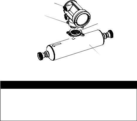
You can rotate an integrally mounted transmitter up to 360° in 90° increments, to one of four possible positions on the core processor base. See Figure 2-2.
Figure 2-2 Rotating the transmitter
Transmitter 
Transition ring
Core processor
4 X Cap screws (4 mm) 


 Base
Base 


 Sensor


 CAUTION
Damaging the wires that connect the transmitter to the core processor can cause measurement error or flowmeter failure.
To reduce the risk of damaging the wires, do not move the transmitter more than a few inches from the core processor. When reassembling the flowmeter, ensure that the wires will not be bent or pinched in the housing.
To rotate the transmitter on the core processor:
1.Loosen each of the four cap screws (4 mm) that fasten the transmitter to the base.
2.Rotate the transmitter counter-clockwise so that the cap screws are in the unlocked position.
3.Gently lift the transmitter straight up, disengaging it from the cap screws. Do not disconnect or damage the wires that connect the transmitter to the core processor.
4.Rotate the transmitter to the desired orientation, and align the slots with the cap screws. Do not pinch or stress the wires.
5.Gently lower the transmitter onto the base, inserting the cap screws into the slots.
6.Rotate the transmitter clockwise so that the cap screws are in the locked position.
7.Tighten the cap screws, torquing to 20 to 30 in-lbs (2,3 to 3,4 N-m).
10 |
Micro Motion® Model 1700 and 2700 Transmitters |
Installing the Transmitter


 CAUTION
Twisting the core processor will damage the sensor.
To reduce the risk of damaging the sensor, do not allow the core processor to rotate.
2.4.24-wire remote or remote core processor with remote transmitter installations
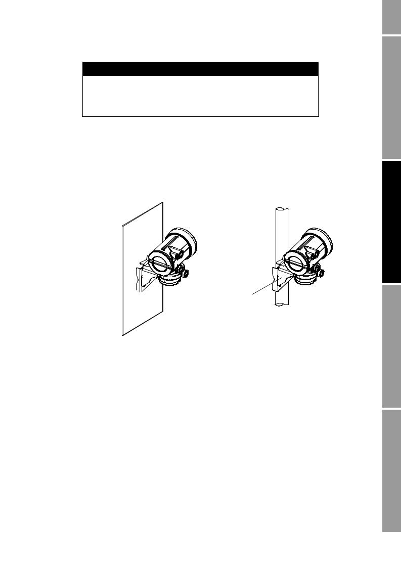
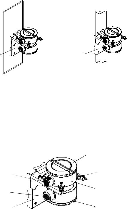
If you chose the 4-wire remote or the remote core processor with remote transmitter installation (see Figure 2-1), see Figure 2-3 for a diagram of the mounting bracket supplied with the transmitter. Both pipe mounting and wall mounting are shown. Ensure that the transmitter is mounted and oriented in a way that will allow easy access to the terminals and to the display (if your transmitter has a display).
Figure 2-3 4-wire remote – Wall mount or pipe mount
Mounting bracket 

 (wall mount)
To mount the transmitter:
Mounting bracket  (pipe mount)
Note: If possible, maintain 8–10″ (200–250 mm) clearance at the rear of the transmitter.
1.Identify the components shown in Figure 2-4. For dimensions, see Appendix A.
2.If desired, re-orient the transmitter on the bracket.
a.Remove the junction end-cap from the junction housing.
b.Loosen each of the four cap screws (4 mm) inside the junction housing.
c.Rotate the bracket so that the transmitter is oriented as desired.
d.Tighten the cap screws, torquing to 30 to 38 in-lbs (3 to 4 N-m).
e.Replace the junction end-cap.
3.Attach the mounting bracket to an instrument pole or wall. For pipe mount, two user-supplied U-bolts are required. Contact Micro Motion to obtain a pipe-mount installation kit if required.
Begin You Before
Transmitter the Installing
Wiring Sensor
Analog – Wiring Output
Installation Manual |
11 |
|
|
|
|
Installing the Transmitter
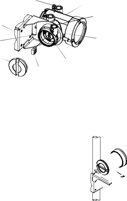
Figure 2-4 Transmitter components – 4-wire remote or remote core processor with remote transmitter installations
Ground screw
|
Main enclosure |
|
Conduit opening |
|
for 4-wire cable |
Mounting bracket |
|
4 X Cap screws |
Junction housing |
|
|
(4 mm) |
|
Junction end-cap |
Mating connector |
|
|
|
socket |
|
Mating connector |
2.4.39-wire remote installations
If you chose a 9-wire remote installation (see Figure 2-1), see Figure 2-5 for a diagram of the mounting bracket supplied with the transmitter/core processor assembly. Ensure that the transmitter is mounted and oriented in a way that will allow easy access to the terminals and to the display (if your transmitter has a display).
Figure 2-5 9-wire remote – Wall mount or pipe mount
Mounting bracket (wall mount)
Mounting bracket (pipe mount)
Note: If possible, maintain 8–10″ (200–250 mm) clearance at the rear of the transmitter.
12 |
Micro Motion® Model 1700 and 2700 Transmitters |
Installing the Transmitter
To mount the transmitter/core processor assembly:
1.Identify the components shown in Figure 2-6. For dimensions, see Appendix A.
2.If desired, re-orient the transmitter on the bracket.
a.Loosen each of the four cap screws (4 mm).
b.Rotate the bracket so that the transmitter is oriented as desired.
c.Tighten the cap screws, torquing to 30 to 38 in-lbs (3 to 4 N-m).
3.Attach the mounting bracket to an instrument pole or wall. For pipe mount, two user-supplied U-bolts are required. Contact Micro Motion to obtain a pipe-mount installation kit if required.
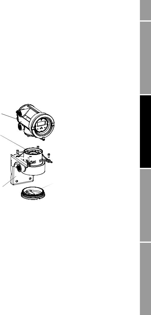
Figure 2-6 Transmitter/core processor assembly – Exploded view
Transmitter 
Core processor 
 4 × Cap screws (4 mm)
Core processor housing 


Conduit opening 

 for 9-wire cable
 End-cap
Mounting bracket 
2.5Mounting the remote core processor
Note: This step is required only for remote core processor with remote transmitter installations (see Figure 2-1). If you have an integral installation, 4-wire remote installation, or 9-wire remote installation, go to Section 2.6.
If you chose the remote core processor with remote transmitter installation (see Figure 2-1), see Figure 2-3 for a diagram of the mounting bracket supplied with the transmitter. Both pipe mounting and wall mounting are shown.
Begin You Before
Transmitter the Installing
Wiring Sensor
Analog – Wiring Output
Installation Manual |
13 |
|
|
|
|
Installing the Transmitter
Figure 2-7 Remote core processor – Wall mount or pipe mount
Mounting bracket |
Mounting bracket |
(wall mount) |
(pipe mount) |
To mount the core processor:
1.Identify the components shown in Figure 2-8. For dimensions, see Appendix A.
2.If desired, reorient the core processor housing on the bracket.
a.Loosen each of the four cap screws (4 mm).
b.Rotate the bracket so that the core processor is oriented as desired.
c.Tighten the cap screws, torquing to 30 to 38 in-lbs (3 to 4 N-m).
3.Attach the mounting bracket to an instrument pole or wall. For pipe mount, two user-supplied U-bolts are required. Contact Micro Motion to obtain a pipe-mount installation kit if required.
Figure 2-8 Remote core processor components
|
Core processor lid |
Conduit opening |
4 × Cap screws (4 mm) |
|
|
for 4-wire cable |
|
Conduit opening |
Core processor housing |
|
|
for 9-wire cable |
|
Mounting bracket |
End-cap |
|
14 |
Micro Motion® Model 1700 and 2700 Transmitters |

Installing the Transmitter
2.6Grounding the flowmeter components
Grounding requirements depend on the installation type (see Figure 2-1). Grounding methods for each flowmeter component are listed in Table 2-3.


 CAUTION
Improper grounding could cause measurement error.
To reduce the risk of measurement error:
•Ground the transmitter to earth, or follow ground network requirements for the facility.
•For installation in an area that requires intrinsic safety, refer to Micro Motion approval documentation, shipped with the transmitter or available from the Micro Motion web site.
•For hazardous area installations in Europe, refer to standard EN 60079-14 if national standards do not apply.
If national standards are not in effect, follow these grounding guidelines:
•Use copper wire, 14 AWG (2,5 mm2) or larger wire size, for grounding.
•Keep all ground leads as short as possible, less than 1 Ω impedance.
•Connect ground leads directly to earth, or follow plant standards.
Table 2-3 Grounding methods for flowmeter components
Installation |
|
|
|
architecture |
Components |
Grounding method |
|
|
|
|
|
Integral |
Sensor / core processor / |
Ground via piping, if possible (see sensor documentation). Otherwise, |
|
|
transmitter |
ground according to applicable local standards using either the |
|
|
|
transmitter’s internal or external ground screw. |
|
|
|
|
|
4-wire remote |
Sensor / core processor |
See sensor documentation. |
|
|
assembly |
|
|
|
|
|
|
|
Transmitter |
Ground according to applicable local standards, using either the |
|
|
|
transmitter’s internal or external ground screw. |
|
|
|
|
|
9-wire remote |
Sensor / junction box |
See sensor documentation. |
|
|
|
|
|
|
Transmitter / core |
Ground according to applicable local standards, using either the |
|
|
processor assembly |
transmitter’s internal or external ground screw, or the core processor’s |
|
|
|
internal ground screw. |
|
|
|
|
|
Remote core |
Sensor |
See sensor documentation. |
|
processor with |
|
|
|
Core processor |
Ground according to applicable local standards, using either the internal |
||
remote |
|||
|
or external ground screw. |
||
transmitter |
|
||
|
|
||
|
Transmitter |
Ground according to applicable local standards, using either the |
|
|
|
transmitter’s internal or external ground screw. |
|
|
|
|
Begin You Before
Transmitter the Installing
Wiring Sensor
Analog – Wiring Output
Installation Manual |
15 |
|
|
|
|
Installing the Transmitter
2.7Supplying power
In all installations, power must be provided to the transmitter. Refer to Section 2.3.3 for information on the transmitter’s power supply requirements.
A user-supplied switch may be installed in the power supply line. For compliance with low-voltage directive 2006/95/EC (European installations), a switch in close proximity to the transmitter is required.
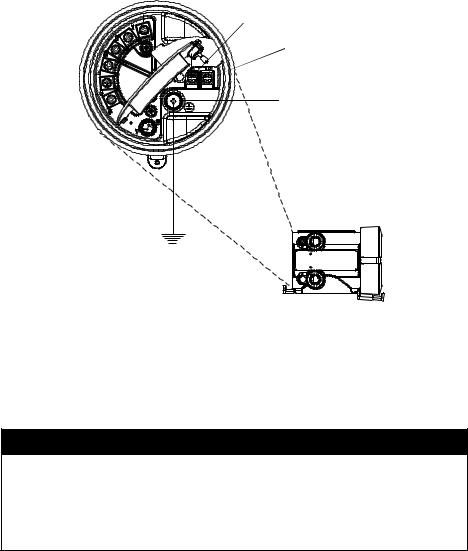
Connect the power supply to terminals 9 and 10, under the Warning flap. Terminate the positive (line) wire on terminal 10 and the return (neutral) wire on terminal 9. Ground the power supply using the equipment ground, also under the Warning flap. See Figure 2-9.
Figure 2-9 Wiring the transmitter power supply
 9
9
 10
10
Equipment ground
Warning flap 
2.8Rotating the display
If your transmitter has a display, you can rotate the display on the transmitter up to 360° in 90° increments.


 WARNING
Removing the display cover in explosive atmospheres while the power is on can cause an explosion.
To reduce the risk of an explosion, before removing the display cover in explosive atmospheres, be sure to shut off the power and wait five minutes.
16 |
Micro Motion® Model 1700 and 2700 Transmitters |
Installing the Transmitter


 WARNING
Using a dry cloth to clean the display cover can cause static discharge, which could result in an explosion in an explosive atmosphere.
To reduce the risk of an explosion, always use a damp cloth to clean the display cover in an explosive atmosphere.
To rotate the display, follow the instructions below:
1.Power down the transmitter.
2.Remove the end-cap clamp by removing the cap screw. See Figure 2-10.
3.Turn the display cover counterclockwise to remove it from the main enclosure.
4.Carefully loosen (and remove if necessary) the semicaptive display screws while holding the display module in place.
5.Carefully pull the display module out of the main enclosure until the sub-bezel pin terminals are disengaged from the display module.
Note: The display pins may come out of the board stack with the display module. If this happens, simply remove the pins and reinstall them.
6.Rotate the display module to the desired position.
7.Insert the sub-bezel pin terminals into the display module pin holes to secure the display in its new position.
8.If you have removed the display screws, line them up with the matching holes on the sub-bezel, then reinsert and tighten them.
9.Place the display cover onto the main enclosure. Turn the display cover clockwise until it is snug.
10.Replace the end-cap clamp by reinserting and tightening the cap screw.
11.Restore power to the transmitter.
Begin You Before
Transmitter the Installing
Wiring Sensor
Analog – Wiring Output
Installation Manual |
17 |
|
|
|
|
Installing the Transmitter
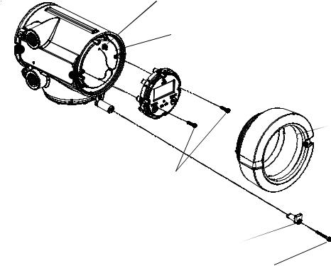
Figure 2-10 Display components
Main enclosure |
Pin terminals |
 Sub-bezel
Display module
Display cover
Display screws 
End-cap clamp 
Cap screw 
18 |
Micro Motion® Model 1700 and 2700 Transmitters |

Chapter 3
Wiring the Transmitter to the Sensor
3.1Overview
This chapter describes how to connect Micro Motion Model 1700 and 2700 transmitters to a Micro Motion sensor.
Note: If you have an integral installation, this step is not required. Continue with wiring the transmitter outputs (Chapters 4–7).
Wiring requirements between the sensor and transmitter depend on the installation type (see Figure 2-1).
•If you have a 4-wire remote transmitter installation, review the information on 4-wire cable in Section 3.2, then follow the instructions in Section 3.3.
•If you have a 9-wire remote transmitter installation, review the information on 9-wire cable in Section 3.2, then follow the instructions in Section 3.4.
•If you have a remote core processor with remote transmitter installation, review the information on both 4-wire and 9-wire cable in Section 3.2, then follow the instructions in Section 3.5.


 CAUTION
Large electromagnetic fields can interfere with flowmeter communication signals.
Improper installation of cable or conduit can cause measurement error or flowmeter failure. To reduce the risk of measurement error or flowmeter failure, keep cable or conduit away from devices such as transformers, motors, and power lines which produce large electromagnetic fields.
3.2Cable types
This section describes the types of 4-wire cable and 9-wire cable that can be used for wiring the transmitter to the sensor.
Begin You Before
Transmitter the Installing
Wiring Sensor
Analog – Wiring Output
Installation Manual |
19 |
|
|
|
|
Wiring the Transmitter to the Sensor
3.2.14-wire cable
Micro Motion offers two types of 4-wire cable: shielded and armored. Both types contain shield drain wires.
User-supplied 4-wire cable must meet the following requirements:
•Twisted pair construction
•The gauge requirements as described in Table 2-2
•The applicable hazardous area requirements, if the core processor is installed in a hazardous area (see the approval documentation shipped with the transmitter or available on the Micro Motion web site)
3.2.29-wire cable
Micro Motion offers three types of 9-wire cable: jacketed, shielded, and armored. Refer to Micro Motion’s 9-Wire Flowmeter Cable Preparation and Installation Guide for detailed descriptions of these cable types and for assistance in selecting the appropriate cable for your installation.
3.3Wiring for 4-wire remote installations
To connect the cable, follow the steps below.
1.Prepare the cable as described in the sensor documentation.
2.Connect the cable to the core processor as described in the sensor documentation.
3.To connect the cable to the transmitter:
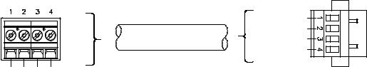
a.Identify the wires in the 4-wire cable. The 4-wire cable supplied by Micro Motion consists of one pair of 18 AWG (0,75 mm2) wires (red and black), which should be used for the VDC connection, and one pair of 22 AWG (0,35 mm2) wires (green and white), which should be used for the RS-485 connection.
b.Connect the four wires from the core processor to terminals 1–4 on the mating connector of the transmitter. See Figures 3-1, 3-2, and 3-3. Never ground the shield, braid, or drain wire(s) at the transmitter.
Figure 3-1 4-wire cable between enhanced core processor and transmitter
Core processor |
4-wire cable |
Mating connector |
terminals |
Maximum cable length: see Table 2-2 |
(transmitter) |
|
|
|
|
|
VDC+ |
|
User-supplied or |
VDC– |
|
RS-485A |
|
|
factory-supplied cable |
|
|
RS-485B |
|
|
|
|
VDC+ (Red) VDC– (Black) RS-485A (white) RS-485B (Green) |
|
|
20 |
Micro Motion® Model 1700 and 2700 Transmitters |
Loading...