


Mass Flow Transmitter 00825-0100-4716

Quick Installation Guide
Start
End
Step 1: Mount the Transmitter
Step 2: Transmitter Installation
Step 3: Software Installation
Step 4: Connect the Wiring and Power Up (HART or Fieldbus)
Step 5: Configure the Transmitter (HART or Fieldbus)
Step 6: Trim the Transmitter
Product Certifications
Product Discontinued
00825-0100-4716, Rev DA
October 2009
Rosemount 3095 MultiVariable
Rosemount 3095 MultiVariable™ Mass Flow
®
Transmitter with HART
or FOUNDATION™
Fieldbus Protocol
Rosemount 3095MF Series Flowmeter Transmitter
www.rosemount.com
¢00825-0100-4716/¤

Quick Installation Guide
IMPORTANT NOTICE
WARNING
00825-0100-4716, Rev DA
Rosemount 3095 MultiVariable
© 2009 Rosemount Inc. All rights reserved. All marks property of owner. Rosemount and the Rosemount logotype are
registered trademarks of Rosemount Inc.
Rosemount Inc.
8200 Market Boulevard
Chanhassen, MN USA 55317
T (US) (800) 999-9307, F (952) 949-7001
T (International) (952) 90 6-8888
Emerson Process Management Asia Pacific
Private Limited
1 Pandan Crescent
Singapore 128461
T (65) 6777 8211, F (65) 6777 0947
This installation guide provides basic guidelines for the Rosemount 3095 MultiVariable
Mass Flow Transmitter (reference manual document number 00809-0100-4716). It also
provides the basic electronics guidelines for the 3095MFA (reference manual document
number 00809-0100-4809), the 3095MFC (reference manual document number
00809-0100-4810) and the 3095MFP (reference manual document number
00809-0100-4686). It does not provide instructions for configuration, diagnostics,
maintenance, service, or troubleshooting. Refer to the appropriate reference manual for
more instruction. These manuals are also available electronically on
www.rosemount.com.
Emerson Process Management GmbH & Co. OHG
Argelsrieder Feld 3
82234 Wessling
Germany
T 49 (8153) 9390, F49 (8153) 939172
Beijing Rosemount Far East Instrument Co.,
Limited
No. 6 North Street,
Hepingli, Dong Cheng District
Beijing 100013, China
T (86) (10) 6428 2233, F (86) (10) 6422 8586
October 2009
Explosions could result in death or serious injury:
Installation of this transmitter in an explosive environment must be in accordance with the
appropriate local, national, and international standards, codes, and practices.
• Before connecting a HART-based communicator in an explosive atmosphere, make
sure the instruments in the loop are installed in accordance with intrinsically safe or
non-incendive field wiring practices.
• In an Explosion-Proof/Flame-Proof installation, do not remove the transmitter covers
when power is applied to the unit.
• Do not remove the transmitter covers in explosive environments when circuit is live.
• Both transmitter covers must be fully engaged to meet explosion-proof requirements.
Process leaks may cause harm or result in death.
• To avoid process leaks, only use the o-ring designed to seal with the corresponding
flange adapter.
Electrical shock can result in death or serious injury.
• Avoid contact with the leads and the terminals. High voltage that may be present on
leads can cause electrical shock.
2
Quick Installation Guide
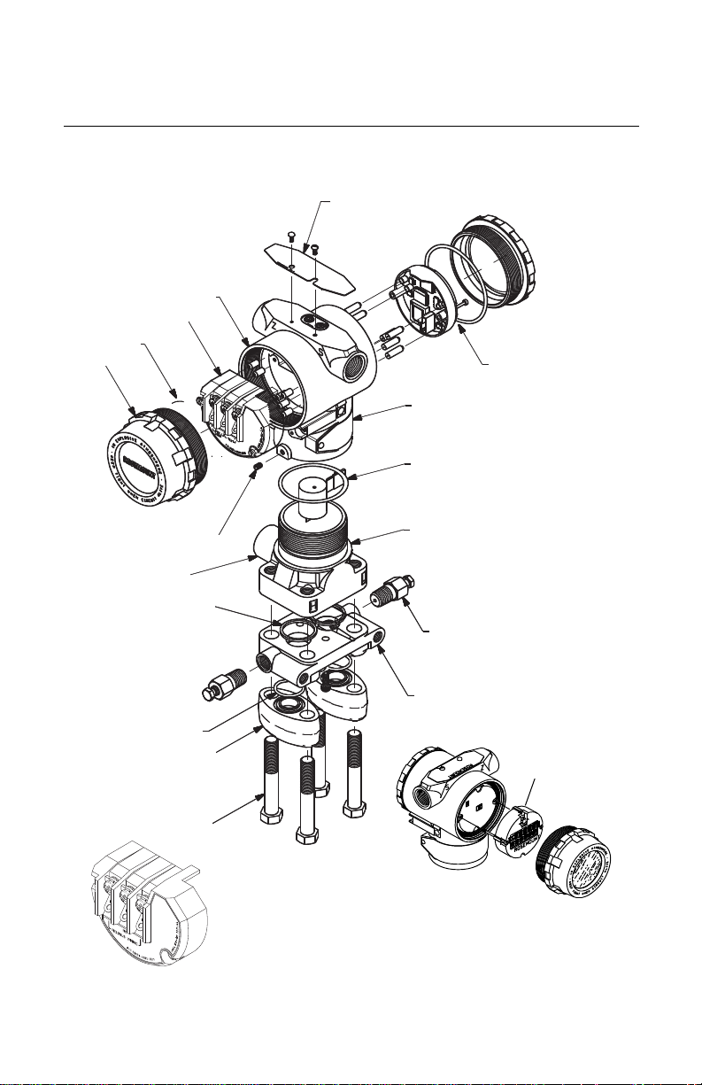
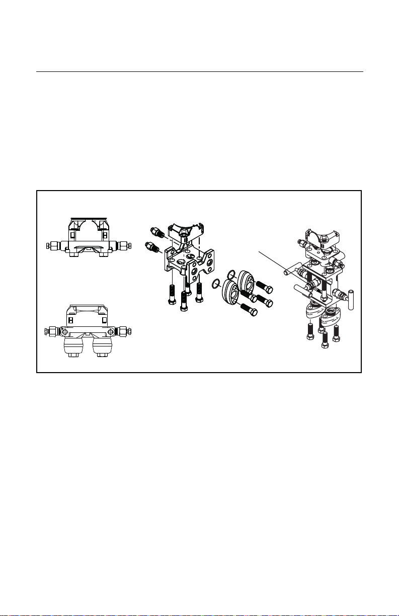
TRANSMITTER EXPLODED VIEW
Housing
O-ring
Cover
Housing Locking Screw
RTD Connector
Process Adapter O-ring
Electronics Board
Nameplate
Module O-ring
Sensor Module
Drain/Vent Valve
Flange Adapter O-ring
Optional Flange Adapters
Bolts
Coplanar Flange
Certification Label
LCD Display Assembly
LCD Display
Cover
Terminal Block
(HART)
Terminal Block (Fieldbus)
00825-0100-4716, Rev DA
October 2009
Rosemount 3095 MultiVariable
3
Rosemount 3095 MultiVariable
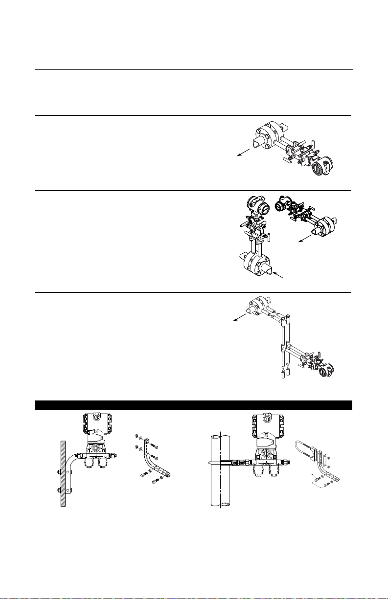
STEP 1: MOUNT THE TRANSMITTER
Flow
Flow
Flow
Flow
Liquid Flow Applications
1. Place taps to the side of the line.
2. Mount beside or below the taps.
3. Mount the transmitter so that the drain/vent
valves are oriented upward.
Gas Flow Applications
1. Place taps in the top or side of the line.
2. Mount beside or above the taps.
Steam Flow Applications
1. Place taps to the side of the line.
2. Mount beside or below the taps.
3. Fill impulse lines with water.
Quick Installation Guide
00825-0100-4716, Rev DA
October 2009
Figure 1. Using a Mounting Bracket
Panel Mount
(1) Panel bolts are customer supplied.
4
(1)
Pipe Mount

Quick Installation Guide
STEP 2: TRANSMITTER INSTALLATION
Housing Rotation Set
Screw (9/64-inch)
00825-0100-4716, Rev DA
October 2009
Rosemount 3095 MultiVariable
Consider Housing Rotation
To improve field access or to better view the optional LCD display:
1. Loosen the housing rotation set screw.
2. Rotate the housing clockwise to the desired position – up to 180° from its original
position. Over rotating will damage the transmitter.
3. If the desired position is attained, tighten the housing rotation set screw.
4. If the desired position cannot be reached because the housing will not rotate further,
rotate the housing counterclockwise until in the desired position is attained (up to 180°
from its original position).
5. Tighten the housing rotation set screw.
Field Installation
1. Mount the transmitter
a.Install the flange or flange/adapter bolt finger-tight.
b.Torque bolts to initial torque value using a cross pattern (see Table 1). When
installing to a mounting bracket, torque bolts to 125 in./lb (169 N/m)
Table 1. Torque Cross Pattern
Bolt Material Initial Value Final Value
Carbon Steel (CS) 300 in./lb (34 N/m) 650 in./lb (73 N/m)
Stainless Steel (SST) 150 in./lb (17 N/m) 300 in./lb (34 N/m)
2. Set the Security Jumper, which is located on the front of the electronics board inside the
electronics housing cover. Putting the Security Jumper in the ON position will protect
against configuration change from being unintentionally made. The transmitter operates
normally if the jumpers are not installed. The Security default is OFF.
5
Quick Installation Guide
STEP 2 CONTINUED...
HART Electronics Board
F
OUNDATION fieldbus Electronics Board
Simulate Jumper
Security Jumper
Washer
Cap
Black Cable Connector
RTD Cap
Conductive Bushing
Connect
to RTD
Compression Fitting
Compression Fitting
Cable Adapter
3
/4 to 1/2-14 NPTAdapter
Bushing
00825-0100-4716, Rev DA
Rosemount 3095 MultiVariable
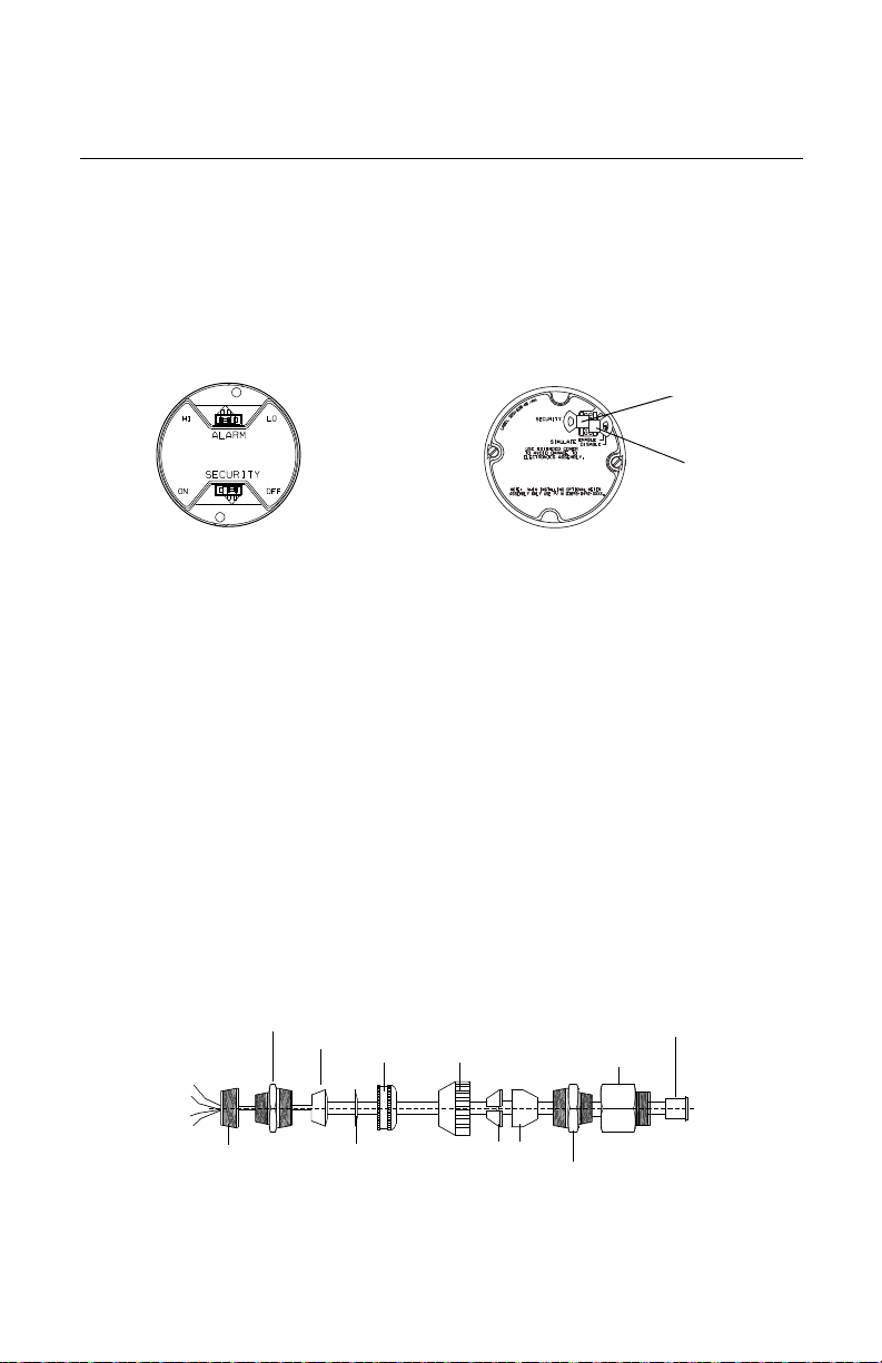
3. Set the Failure Mode Alarm (HART devices), which is located on the front of the
electronics board inside the electronics housing cover. The Alarm Jumper position
determines if the output is driven high or low when a failure is detected. The transmitter
operates normally if the jumpers are not installed and the Alarm default fail is HI.
Figure 2. Alarm Jumper Location
4. Set the Simulate Jumper (FOUNDATION fieldbus devices), which is located on the front of
the electronics board inside the electronics housing cover. The jumper is used to
simulate the measurement and is used as a lock-out feature for the AI function block. To
enable the simulate feature, insert the jumper across ENABLE while the transmitter is
powered. The default position for the Simulate Jumper is DISABLE. Enable the simulate
feature after power is applied to the device. Simulate is automatically disabled
regardless of jumper position if power is cycled.
5. Connect the transmitter to the process.
6. Install the RTD Cable Assembly (optional). All RTD 3095 Cable Assemblies use the
3095 RTD Cable Connector. Identify the cable type being installed and follow the steps
below.
• Installing an Armored Shielded RTD Cable (See Figure 3)
a.Fully engage the black cable connector to the 3095 RTD connector.
b.Tighten the cable adapter until metal contacts metal.
c.Install the compression fitting.
d.Tighten the cap onto the compression fitting.
October 2009
Figure 3. Armored Shielded RTD Cable
6
Quick Installation Guide
STEP 2 CONTINUED...
Cable Adapter 1/2–14 NPT
Black Cable Connector
Black Cable Connector/ RTD Connector
Cable Adapter
Cable Gland
RTD Cable Gland CM20
00825-0100-4716, Rev DA
October 2009
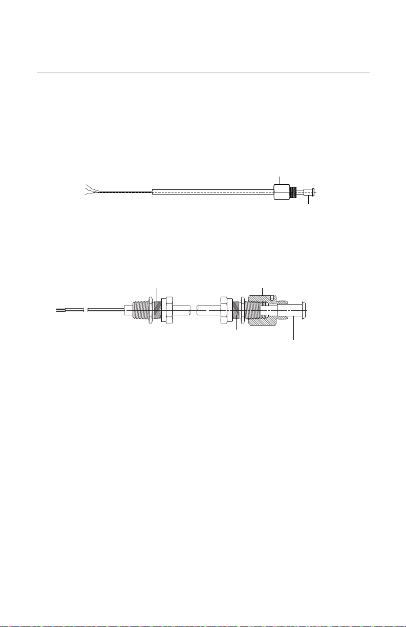
• Installing a Shielded 3095 RTD Cable (See Figure 4)
Note: Shielded cable is intended for use in a conduit.
a.Fully engage the black cable connector to the 3095 RTD Connector.
b.Tighten the cable adapter until metal contacts metal.
Figure 4. Shielded RTD Cable
• Installing a ATEX/IECEx Flameproof 3095 RTD Cable (See Figure 5)
a.Fully engage the black cable connector to the 3095 RTD Connector.
b.Tighten the cable adapter and cable gland until metal contacts metal.
Figure 5. ATEX/IE CEx Flameproof RTD Cable
Rosemount 3095 MultiVariable
7. Check all process connections for leaks.
8. Connect the appropriate wiring (see Step 5). Ground the transmitter according to
national and local electrical codes. Install field wiring grounding (optional).
7
Quick Installation Guide
STEP 2 CONTINUED...
4 x 1.75-in. (44 mm)
4 x 2.88-in. (73 mm)
A. Transmitter with
Coplanar Flange
B. Transmitter with Copla nar
Flange and Optional
Flange Adapters
C. Transmitter with Traditional
Flange and Optional Flange
Adapters
D. Transmitter with
Coplanar Flange and
Optional Manifold and
Flange Adapters
4 x 1.75-in. (44 mm)
4 x 1.50-in. (38 mm)
4 x 1.75-in. (44 mm)
4 x 2.25-in. (57 mm)
00825-0100-4716, Rev DA
Rosemount 3095 MultiVariable
October 2009
Bolting Considerations
If the transmitter installation requires assembly of the process flanges, manifolds, or flange
adapters, follow these assembly guidelines to ensure a tight seal for optimal performance
characteristics of the transmitters. Use only bolts supplied with the transmitter or sold by
Emerson as spare parts. Figure 6 illustrates common transmitter assemblies with the bolt
length required for proper transmitter assembly.
Figure 6. Common Transmitter Assemblies
Bolts are typically carbon steel or stainless steel. Confirm the material by viewing the
markings on the head of the bolt and referencing Figure 7. If bolt material is not shown in
Figure 7, contact the local Emerson Process Management representative for more
information.
Use the following bolt installation procedure:
1. Carbon steel bolts do not require lubrication and the stainless steel bolts are coated with
a lubricant to ease installation. However, no additional lubricant should be applied when
installing either type of bolt.
2. Finger-tighten the bolts.
3. T orque the bolt s to the initial torque value using a crossing pattern. See Figure 7 for initial
torque value.
4. Torque the bolts to the final torque value using the same crossing pattern. See Figure 7
for final torque value.
5. Verify that the flange bolts are protruding through the isolator plate before applying
pressure.
8
Quick Installation Guide
STEP 2 CONTINUED...
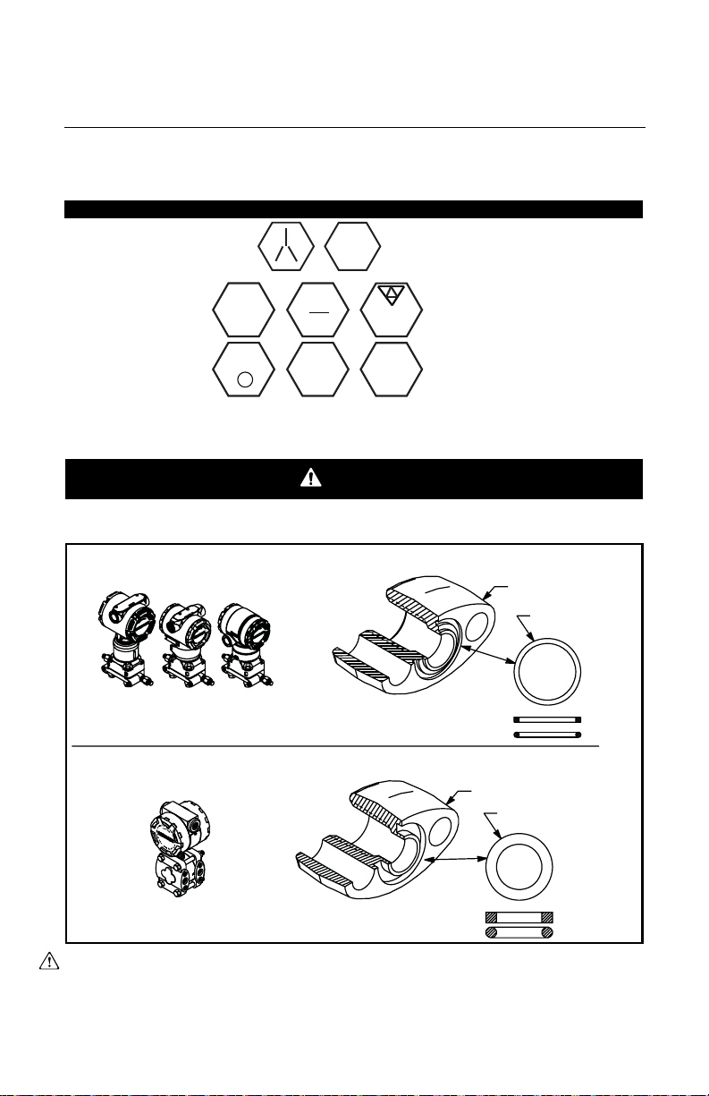
WARNING
B7M
316
316
316
SW
316
STM
316
R
B8M
Rosemount 3051S / 3051 / 2051 / 3095
Rosemount 1151
Flange Adapter
O-ring
Flange Adapter
O-ring
PTFE Based
Elastomer
PTFE
Elastomer
00825-0100-4716, Rev DA
October 2009
Figure 7. Torque values for the flange and flange adapter bolts
Bolt Material Head Markings Initial Torque Final Torque
Carbon Steel (CS) 300 in.-lbs. 650 in.-lbs.
Stainless Steel (SST) 150 in.-lbs. 300 in.-lbs.
Rosemount 3095 MultiVariable
O-rings with Flange Adapters
Failure to install proper flange adapter O-rings may cause process leaks, which can result in death or
serious injury. The two flange adapters are distinguished by unique O-ring grooves. Only use the O-ring
that is designed for its specific flange adapter, as shown below.
Whenever the flanges or adapters are removed, visually inspect the o-rings. Replace them if
there are any signs of damage, such as nicks or cuts. If the o-rings are replaced, re-torque
the flange bolts and alignment screws after installation to compensate for seating of the
PTFE o-ring.
9

Quick Installation Guide
STEP 3: SOFTWARE INSTALLATION
00825-0100-4716, Rev DA
Rosemount 3095 MultiVariable
The 3095 Engineering Assistant (EA) for HART and 3095 Engineering Assistant (EA) for
FOUNDATION Fieldbus software programs can be installed on the same computer. The
applications cannot be open simultaneously.
October 2009
3095 Engineering Assistant (EA) for HART Software Installation
1. Install the Program
a.Place the CD-ROM in the drive and run setup.exe from Windows NT, 2000, or XP.
b.After installing the software, install the HART Modem (see “Installing the HART
Modem” on page 11).
2. Upgrade the previous versions of Engineering Assistant program (if required)
a.Place the CD-ROM disk 2 into the drive and run the EAUpgrade.exe from Windows
98, NT, 2000, or XP. To properly install, the program will first uninstall Engineering
Assistant from the computer. (Upgrades also are available at www.rosemount.com.)
b.Remove the installation disk and reboot the computer to complete installation.
c.To install the upgraded program, run the EAupgrade.exe from Windows 95,98, or
NT again.
3. Connect the computer to the 3095 transmitter.
a.Connect the HART modem cable to the computer using the 9-pin serial or USB
communications port on the computer.
b.Open the cover above the side marked Field Terminals, and connect the
mini-grabbers to the two 3095 terminals marked COMM.
4. Select Engineering Assistant for HART from the program menu.
On-Line Mode: EA communicates directly with the 3095 through AMS.
a.In AMS Explorer view or AMS Connection view, right-mouse click on a 3095 device
tag or icon.
b.Select SNAP-ON/Linked Apps > Engineering Assistant.
Off-Line Mode: Engineering Assistant does not communicate directly with the 3095.
Instead, the EA configuration is sent to a 3095 later when Engineering Assistant is in
on-line mode. In the off-line mode a future device needs to be created in order to launch
Engineering Assistant.
a.In AMS Explorer view or AMS Device Connection view, left click on Plant Database
to the Area folder.
b.Left click on Area to the Unit folder.
c.Left click on Unit to the Equipment Module folder.
d.Left click on Equipment Module to the Control Module folder.
e.right-mouse click on Control Module to the pop-up context menu.
f. Select Add Future Device.
g.Select 3095MV Template and click OK.
h.Right-mouse click on Future device to pop-up context menu.
i. Select SNAP-ON/Linked Apps > Engineering Assistant.
10
 Loading...